


🚨 Scope and compliance: The names, scope (each axis / common to all axes) and example settings for 1410 and 1420-1425 come from the official Fanuc
0i-MODEL C / 0i Mate-MODEL C START-UP MANUAL, section “NC parameters related to axis settings”.1428and1430come from published Chinese parameter summaries and have a different scope from the official table; this page does not adjudicate which is correct and requires each number to be checked against the supplied manual. G12 (*FV0–*FV7), G14.0 / G14.1 (ROV1 / ROV2), G6.4 (OVC),*JV(G10 / G11), SOV (G30), MP1 / MP2 (G19.4 / G19.5) and the#3004macro variable come from published PMC signal tables, course material and third-party technical sites; some bit assignments and step encodings differ between control generations and must be confirmed against the supplied connection manual and builder ladder, and this is not advice to rewire or edit a ladder. Manual text, ladder diagrams and bit-definition figures are copyright material; this page explains mechanisms and diagnostic order only, and offers no manual download link, file mirror, archive or bundled package. Every setting must be checked against the CNC model, software version, supplied manual and builder specification; the override switch X addresses and decoding logic are defined by the machine builder, not by Fanuc.
30-Second Triage: Identify Which Segment You Are In
Table 0 – Eight symptoms and the first diagnostic line
1. How Many Override Families Are There, Really
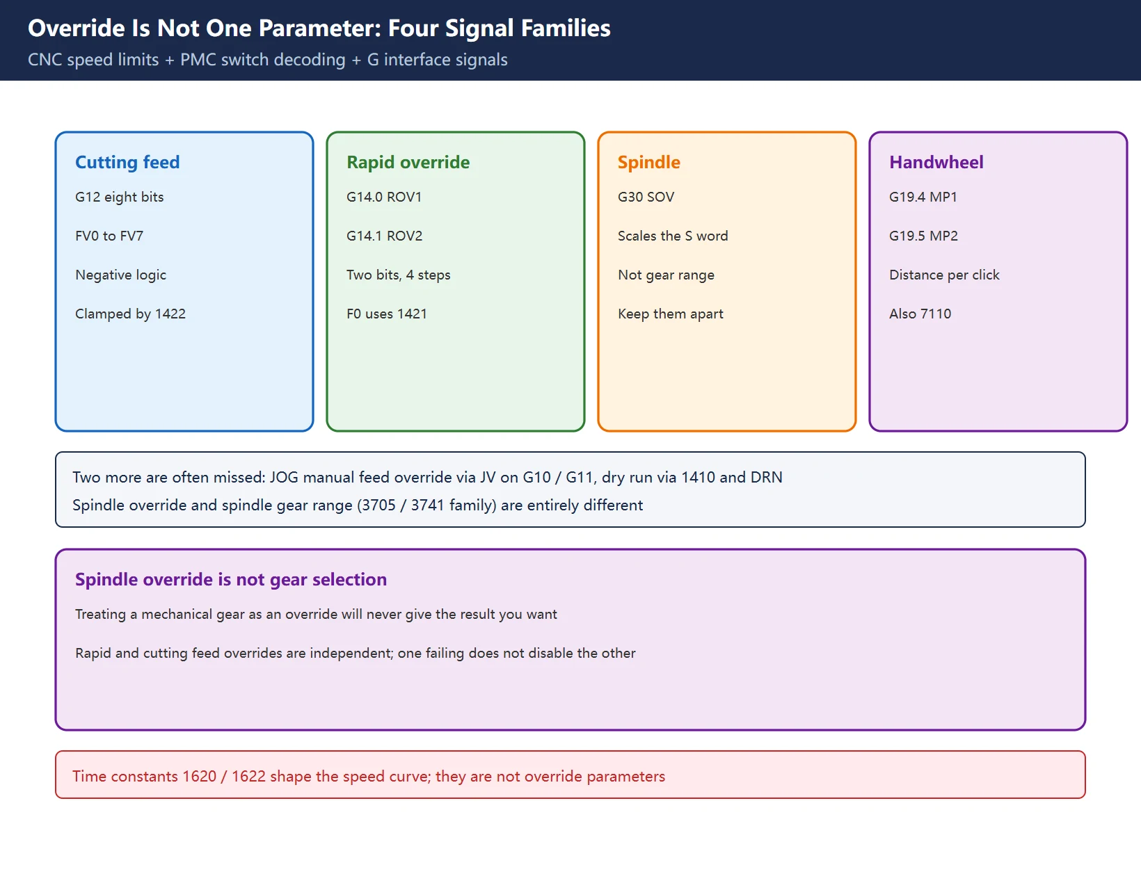
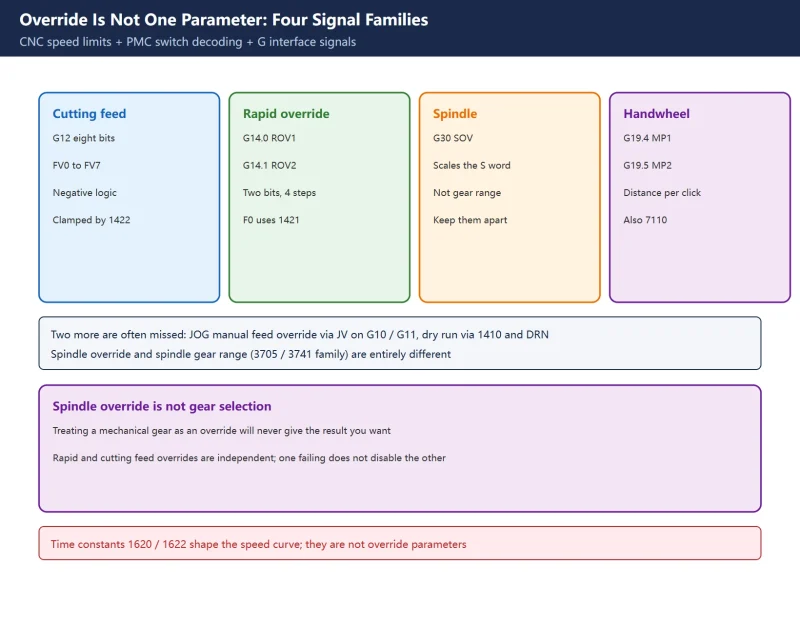
“Four overrides” is a field shorthand. Counting at the signal level gives more, and laying them out explains why editing one parameter never fixes an override problem:
| Override | What it scales | CNC interface signal (third-party tables) | Speed reference |
|---|---|---|---|
| Cutting feed override | Percentage of the programmed F word | G12, *FV0–*FV7, 8-bit negative logic | Ceiling clamped by 1422 |
| Rapid traverse override | G00 rapid step | G14.0 / G14.1 (ROV1 / ROV2) | 1420 rapid rate, 1421 for the F0 step |
| Spindle override | Percentage of the S word | G30, SOV0–SOV7 | Spindle-side parameters, out of scope here |
| Handwheel / incremental override | Distance per handwheel click | G19.4 / G19.5 (MP1 / MP2) | 7110 handwheel count, 7113 / 7114 arbitrary magnification (third-party) |
| JOG manual feed override | Manual continuous feed | G10 / G11, *JV | 1423 JOG feedrate |
| Dry run | Fixed speed replacing programmed F | G46.7 (DRN) | 1410 dry run rate |
Table 1 – Six override / speed paths and who owns each
Two concepts must be kept apart: spindle override (a percentage of S, via G30) and spindle gear range selection (a mechanical gear, via 3705 / 3732 / 3741 family parameters, see FANUC Spindle Gear Shifting) are entirely different things. Treating gear selection as an override will never produce the result you want. Likewise, rapid override and cutting feed override are independent signals; one failing does not disable the other.
Two site articles often pulled into this topic: FANUC Acceleration / Deceleration 1620 / 1622 changes the shape of the speed curve, not the override; FANUC MPG Handwheel Signal Chain covers handwheel hardware and I/O, not MP1 / MP2 step decoding.
2. The Official 1420-1425 Split: Six Numbers, Different Jobs
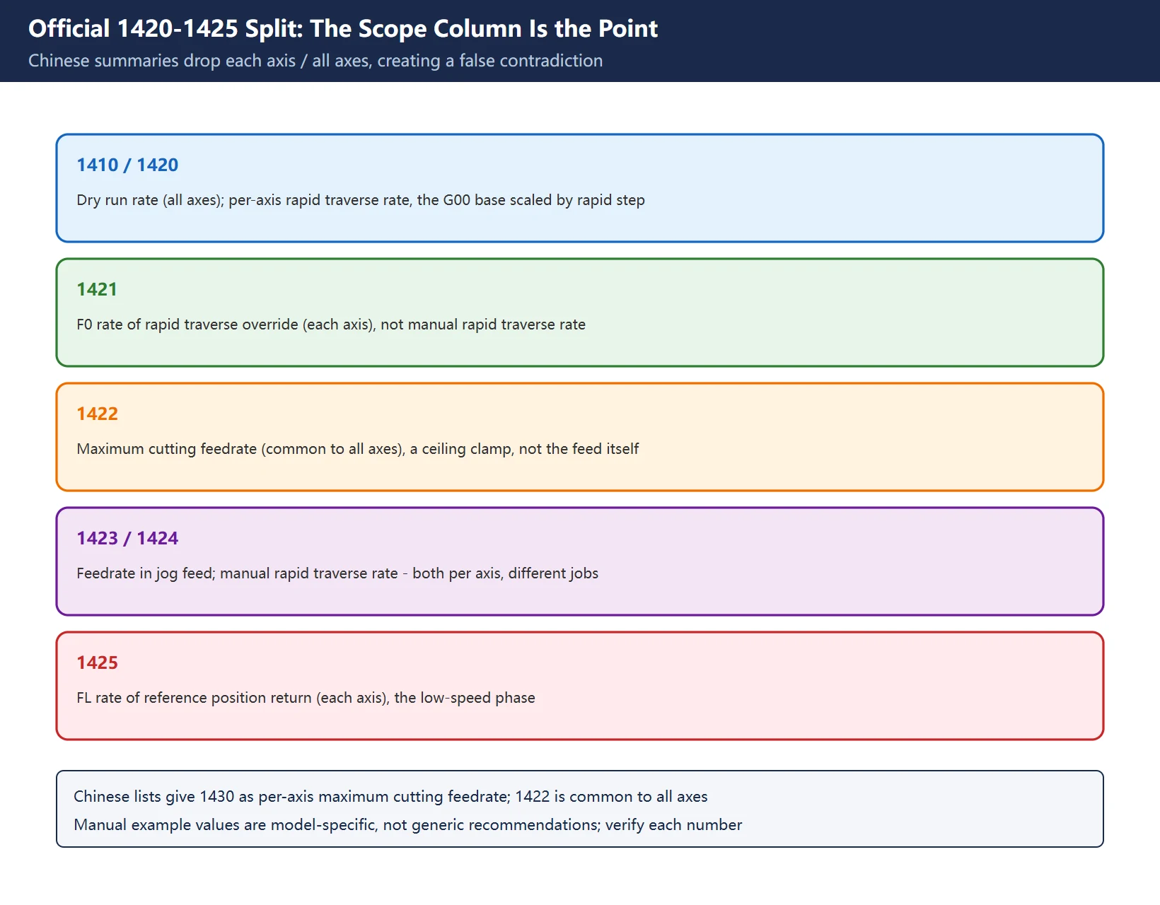
The official Fanuc 0i-MODEL C start-up manual lists this group in its “NC parameters related to axis settings” table. The critical difference is the scope column: “each axis” versus “common to all axes.” Chinese summary tables drop that column – which is exactly how the apparent contradiction “both 1422 and 1430 are maximum cutting feedrate” is created.
| Parameter | Official name | Scope | Field reading |
|---|---|---|---|
| 1410 | Dry run rate | All axes | Substitute speed during dry run, not an override |
| 1420 | Rapid traverse rate | Each axis | G00 base speed, scaled by the rapid override step |
| 1421 | F0 rate of rapid traverse override | Each axis | Low speed for the F0 step, not “manual rapid” |
| 1422 | Maximum cutting feedrate | Common to all axes | A ceiling clamp, not the feed rate itself |
| 1423 | Feedrate in jog feed | Each axis | Base speed for manual continuous feed |
| 1424 | Manual rapid traverse rate | Each axis | Rapid speed in manual mode |
| 1425 | FL rate of reference position return | Each axis | Low-speed phase after deceleration during reference return |
Table 2 – Official 1410 / 1420-1425 split (from the 0i-MODEL C START-UP MANUAL)
The same page gives one initialisation example (1410=1000, 1420=8000, 1421=1000, 1422=10000, 1423=1000, 1424=5000, 1425=150) plus the 1620 / 1622 / 1624 acceleration-deceleration time constants. These are examples from that manual, not generic recommended values; an order-of-magnitude difference between machine models is normal, so no copy-ready settings are given here.
Now consider two numbers in Chinese summaries: 1428 (reference return feedrate per axis) and 1430 (each axis maximum cutting feedrate). Putting 1430 next to the official 1422 (common to all axes maximum cutting feedrate) shows the scopes are different – once the “each axis / all axes” column is deleted, the two Chinese descriptions look identical. The same omission makes 1421 (F0 step speed) and 1424 (manual rapid speed) both appear as “manual rapid traverse rate” in some tables. This page does not rule on which number is valid in which generation; every one must be verified line by line against the supplied parameter manual for bit definitions and units. This is the same discipline as the 1422 / 1430 and 1421 / 1424 conflict recorded in the Fanuc Parameter Number Map.
🔑 That answers the frequent question: editing 1422 will not change feed rate. 1422 is the ceiling, not the throttle. Actual cutting feed = programmed F × feed override, clamped by 1422; change F or the override to change speed, and only edit 1422 to change the ceiling. Rapid works the same way: rapid speed = 1420 × rapid override step, with the F0 step using 1421 directly.
3. Signal-Side Wiring: The Switch Never Talks to the Interpolator Directly
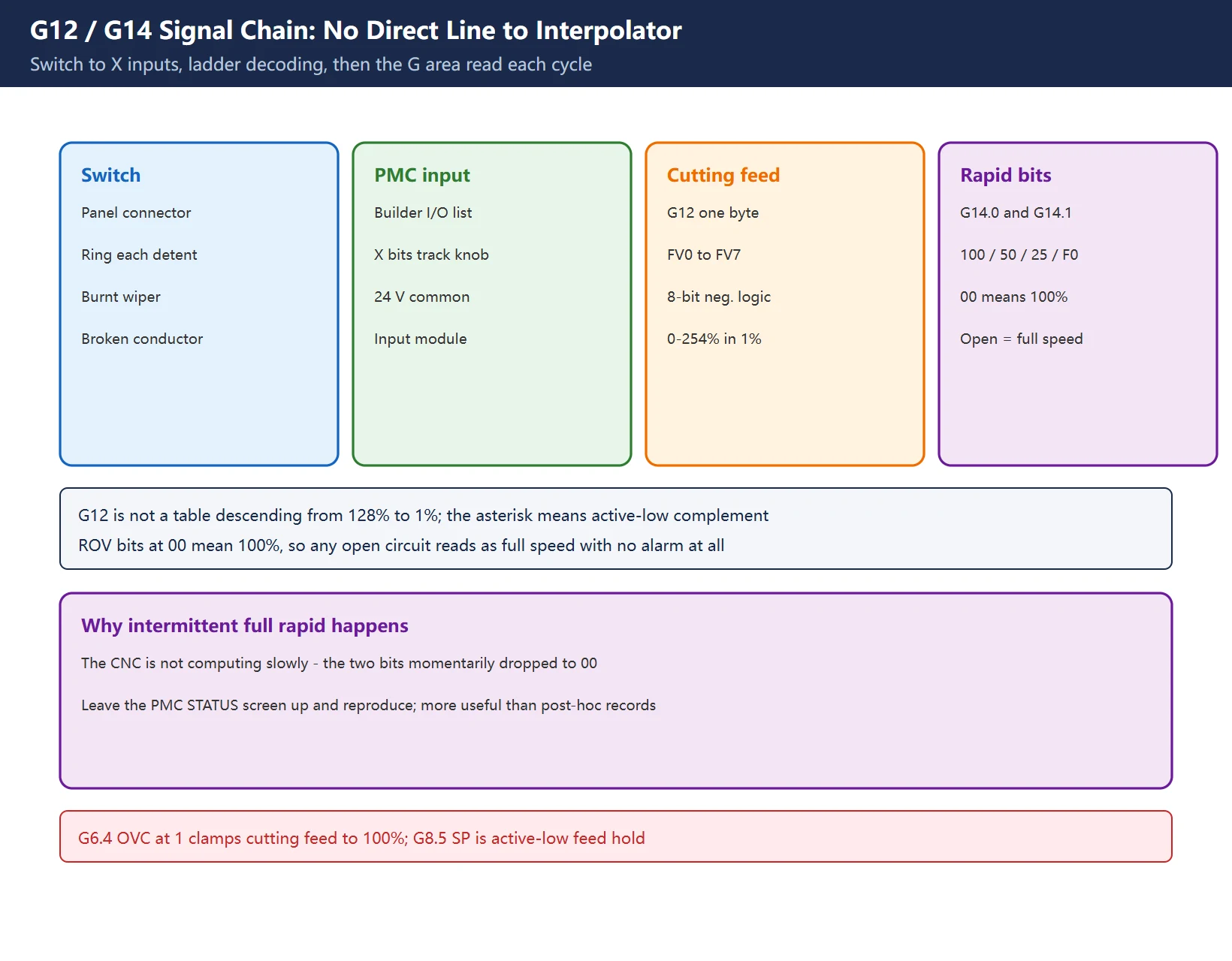
This is the chain an electrical maintenance engineer should memorise: the override switch never connects directly to the CNC interpolator. Its contacts land on PMC X inputs, the builder’s ladder decodes them into a byte (commonly a CODB conversion, a data table and a logical-OR transfer), and writes that into the CNC interface G area, which the CNC reads each cycle. So “override not working” has four entirely different break points; eliminate them in order rather than swapping parts at random.
| Segment | Address / element | Passing condition | What a failure means |
|---|---|---|---|
| Switch contacts | Panel connector, builder schematic | Continuity changes at every detent | Burnt wiper, broken conductor |
| PMC input | X address from builder I/O list | Bits change as the switch turns | 24 V common, input module |
| Cutting feed override | G12 (*FV0–*FV7) | Byte tracks the switch | Ladder decoding or PMC parameters |
| Override cancel | G6.4 (OVC) | Should be 0 | A 1 clamps cutting feed to 100% |
| Rapid override | G14.0 / G14.1 (ROV1 / ROV2) | Bits follow the detent | An open circuit reads as 100% |
| Feed hold | G8.5 (*SP) | 1 during a cycle | Negative logic; 0 means feed hold |
Table 3 – Six segments of the override signal chain (addresses per supplied connection manual and builder ladder)
Two widespread errors must be corrected here:
- G12 is not “128% down to 1% in 8 bits.” It is 8-bit negative logic (the
*in the mnemonic means active-low; the ladder writes the complement of the desired percentage), and public sources give a coverage of 0-254% in 1% steps. A Chinese signal table splits it into two formula ranges (0-127% and 128-254%), but under either description it should not be presented as a table descending from 128% to 1%. - The fourth rapid-override step is F0, not 10%. ROV1 / ROV2 combine into four steps: 100% / 50% / 25% / F0, with the F0 speed set by parameter 1421. In the standard encoding given by third-party sources,
00corresponds to 100% – which means any open circuit, lost 24 V common or ladder branch that clears both bits is read as 100%, with no alarm at all. That explains intermittent “full rapid in cold weather” cases: the CNC is not computing slowly, the two bits momentarily dropped to 00.
For PMC address distinctions (G / R / D) see What Is a PMC in Fanuc? Ladder Logic and Addresses; for reaching the screens see Fanuc 0i-MD PMC Diagnostic Screens; for I/O group / base / slot notation see Fanuc I/O Link Address Assignment.
4. Clamping at 100%: G6.4 Affects Cutting Feed Only
When G6.4 (OVC, override cancel) is 1, the cutting feed override is clamped to 100% and the panel feed-override knob has no effect. This is standard for safety reviews, batch production and thread cutting: allowing an operator to change the override during tapping or threading breaks the spindle-to-axis synchronisation and directly causes pitch errors (see Fanuc Threading G32 / G92 / G76). Some builders use M48 / M49 auxiliary functions to switch OVC on and off – that is builder ladder logic, not a fixed Fanuc command.
But the phrase “override clamped at 100%” misses an important limit: published course material states explicitly that OVC fixes only the cutting feed override; rapid traverse override and spindle speed override are unaffected. So if rapid and spindle overrides still work after OVC is set, that is correct behaviour, not a failure to clamp. Conversely, if adjusting the cutting feed override also freezes rapid and spindle, the problem is not OVC – go back to the G12 byte and the X inputs.
| Affected by OVC | Not affected by OVC |
|---|---|
| Cutting feed override (G12) → clamped to 100% | Rapid override (G14.0 / G14.1) |
| Scaling of programmed F through G12 | Spindle override (G30) |
| Master-slave safety in tapping / threading | JOG manual feed override (G10 / G11) |
Table 4 – The boundary of OVC (from published course material; verify bit addresses)
5. Relationship to Diagnostic Screens: Correcting the 3111 Bits
The brief that prompted this page lumped “3111#0 / 3111#5” together as “operation monitor display switches → load meter and speed meter readings”. Those are two different functions. In published Chinese parameter summaries, the 3111 bits are:
| Bit | Name | Function |
|---|---|---|
| 3111#0 | SVS | Whether the soft key for the servo setting screen is displayed |
| 3111#1 | SPS | Whether the soft key for the spindle setting screen is displayed |
| 3111#5 | OPM | Whether operation monitor display is performed (axis load torque, etc.) |
| 3111#6 | OPS | Whether the operation monitor speed meter shows spindle motor speed or spindle speed |
| 3108#6 | SLM | Whether the spindle load meter is shown (only if 3105#2 DPS=1 and a serial spindle) |
| 3192#7 | PLD | Servo axis load meter and spindle speed meter on the left half of a 10.4-inch display |
Table 5 – Display bit definitions (third-party summary; verify against the supplied manual)
So: #0 is a servo setting screen soft key; #5 is the operation monitor. For load meter work, the main thread is 3111#5 / 3108#6 / 3192#7 cross-checked against diagnostic numbers 200-204 / 300, covered in Fanuc Servo Load Meter Explained and FANUC Diagnostic Number (DGN) Reference. Display bits change what you can see, not any override or speed – do not spend diagnostic time on this layer.
6. Four Failure Checks: Follow the Order, Do Not Skip
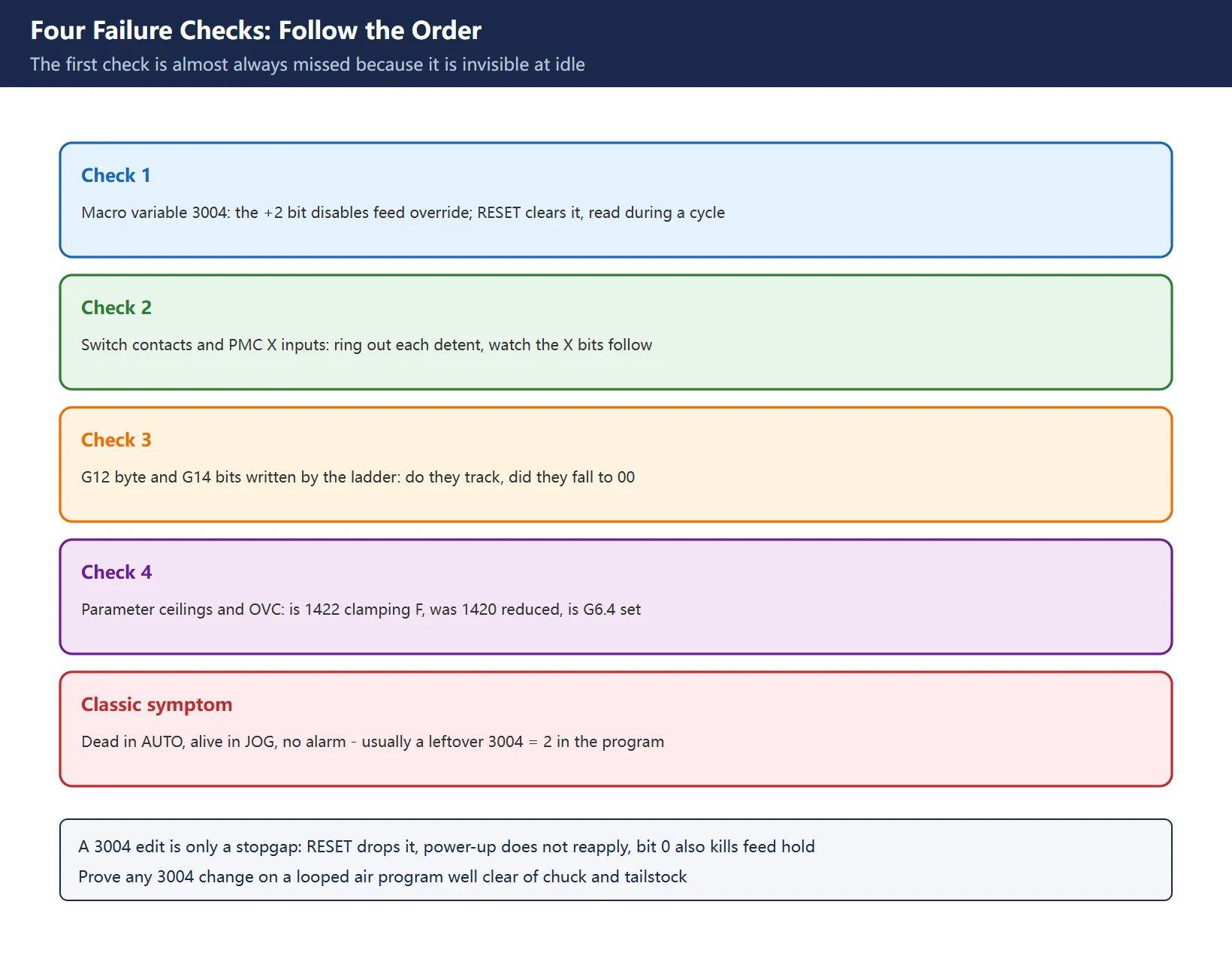
The previous sections combine into one field route. A third-party technical source gives a very typical case: the override knob is completely dead in AUTO but works in JOG, with no alarm at all – because a program left #3004 = 2 behind. Almost everyone misses this check, so it comes first.
| # | Check | How to judge | Common mistake |
|---|---|---|---|
| 1 | Program-side macro variable #3004 | The +2 bit disables feed override; +1 disables feed hold, +4 disables exact stop check; =0 means all active | RESET clears it – a 0 at idle proves nothing; read it while the cycle runs |
| 2 | Switch contacts and PMC X inputs | Ring out each detent; watch the X bits in PMCDGN / STATUS | Replacing the knob before checking the ladder |
| 3 | G12 / G14 written by the ladder | Does the G12 byte track? Did G14 fall to 00? | Forgetting G12 is negative logic and 00 means 100% |
| 4 | Parameter ceilings and OVC | Is 1422 clamping F, was 1420 reduced, is G6.4 set? | Treating a ceiling as a speed, or OVC as clamping all overrides |
Table 6 – Four ordered override failure checks (skipping a step causes misdiagnosis)
Step 1 needs care: #3004 is a macro variable that only applies while the program runs. Adding #3004=0 at the program head is at best a get-through-the-shift measure – RESET drops it and power-up does not reapply it – and changing bit 0 at the same time also disables feed hold, so any #3004 change should be proven on a looped air program well clear of the chuck and tailstock. For ladder-side order see FANUC PMC Ladder Diagram Beginner Tutorial, and for write access see FANUC Parameter Write Protect (PWE).
7. Lookup Keys and an Internal Index
| Lookup key | Question it answers | Where to look |
|---|---|---|
| CNC model + software version | Whether 1422 or 1430 applies here, and its scope | Supplied parameter manual cover, SYSTEM version screen |
| FEED RATE group in the parameter manual | Official names for 1410 / 1420-1425 and the each axis / all axes column | Start-up manual, “NC parameters related to axis settings” |
| Supplied connection manual (Function) | Exact addresses and negative-logic encoding for G12 / G14 / G6.4 | Signal tables plus builder ladder cross-reference |
| Builder I/O list | Which X points the switch uses, and the decoding table | Panel schematic plus PMC cross-reference |
Table 7 – Four lookup keys and the question each answers
Related on this site: Fanuc Servo Load Meter Explained · FANUC Acceleration / Deceleration and Corner Slowdown · Fanuc Parameter Number Map · Why Is a Fanuc Parameter Missing? · Fanuc Tool Setter / Probe Calibration · FANUC Parameter Write Protect (PWE) · FANUC Diagnostic Number (DGN) Reference · Fanuc 0i-MD PMC Diagnostic Screens · Fanuc I/O Link Address Assignment · FANUC PMC Parameter Tables · FANUC Spindle Gear Shifting · Fanuc Threading G32 / G92 / G76 · FANUC MPG Handwheel Signal Chain · What Is a PMC in Fanuc? Addresses and Scan Time · FANUC PMC Ladder Diagram Beginner Tutorial · FANUC 0i-Mate / 0i-D Alarm Quick Reference · FANUC Parameter Cross-Reference by Control Generation.
Frequently Asked Questions
What is the Fanuc feed override parameter, and why does editing 1422 not change the feed rate?
Because 1422 is not a feed rate. The official 0i-MODEL C start-up manual defines 1422 as “Maximum cutting feedrate, common to all axes” – a ceiling clamp. Actual cutting feed = programmed F × feed override (G12), then clamped by 1422; to change speed, change F or the override knob, and only edit 1422 to change the ceiling. Also note that Chinese summary tables list 1430 as “maximum cutting feedrate per axis”, with a different scope from 1422; several manual generations have been spliced into one table, making them look like the same number. Verify line by line against the supplied manual and never copy values from another machine. By the same token, 1421 is the F0 rapid-override step speed, while 1424 is the manual rapid traverse rate.
How is an override switch wired to a Fanuc, and which signals are involved?
The switch does not go into the CNC directly. The path is: panel rotary contacts → PMC X inputs (addresses defined by the builder I/O list) → builder ladder decoding (commonly CODB plus a data table) → the CNC interface G area. Cutting feed override uses G12 (*FV0–*FV7, 8-bit negative logic; public sources give 0-254% in 1% steps). Rapid override uses G14.0 / G14.1 (ROV1 / ROV2), two bits combining into 100% / 50% / 25% / F0, with the F0 speed set by 1421 – the fourth step is F0, not 10%. Signals marked with * are active-low, so the ladder writes the complement; all-zero bits mean 100%, which is why a broken wire looks like permanent full speed with no alarm. JOG manual feed override is *JV on G10 / G11, spindle override is SOV on G30, and handwheel override is G19.4 / G19.5. Confirm all addresses and encodings against the supplied connection manual and the machine’s ladder.
How do I clamp the override at 100%, and what is G6.4?
G6.4 is OVC (override cancel). When set to 1, the cutting feed override is fixed at 100% and the panel knob has no effect – commonly used in tapping and threading to protect pitch, with some builders driving it from M48 / M49 in the ladder. Mind the boundary: published course material states that rapid traverse override and spindle speed override are not affected by OVC, so those still working afterwards is normal. There is also a separate “looks clamped” case that is not OVC: a leftover #3004 = 2 disables feed override and presents as dead in AUTO, alive in JOG, with no alarm – and RESET clears the variable, so read the macro variable screen while the cycle is running, not at idle. For write access see the PWE page, and remember the ladder decoding is builder-defined: archive it before any change.
Last updated: 2026-11-15
Where to go next
- FANUC Troubleshooting — the full guide library: alarms, diagnosis numbers, servo, spindle, PMC and electrical faults, organised by symptom.
- CNC Repair Tools — which instrument measures what: multimeters, clamp meters, insulation testers and oscilloscopes, with the specification that actually matters.
- Remote Technical Support — have the readings reviewed with you: alarm reverse lookup, PMC ladder analysis and servo tuning advice by call. Repair companies and integrators welcome.
Read the guide, get the right instrument, or walk the diagnosis through with someone — pick whichever you need.
The original Chinese version — same procedure, with the full field notes.
























暂无评论内容