


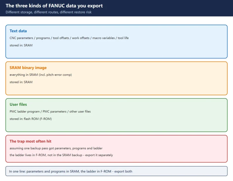
Alarm definitions in this article come from the FANUC Series 0i-MODEL D / 0i Mate-MODEL D Maintenance Manual (B-64305EN/03), Appendix A alarm list. The sync-chain description comes from the FANUC Series 15/150-Model B Connection Manual (B-62073E-1/04), section “Threading with a desired gear ratio”. 🚨 Parameter numbers and screen names are not portable across control series and software versions. This guide deliberately gives no copy-and-paste parameter numbers; always use the parameter manual shipped with the machine, and back up parameters and ladder first (parameter and ladder export). For write-enable, see FANUC Parameter Write Protect (PWE).
30-second triage
| Symptom | First suspect | First action |
|---|---|---|
| Start point drifts, a step appears at the pick-up point | Unstable one-rotation signal / approach distance not an integer multiple of the lead | Use SERVO GUIDE to check the one-rotation signal and Z-axis entry delay |
| Pitch drifts gradually along the full length | Coder-to-spindle gear ratio / Z-axis positioning accuracy or pitch comp | Verify the coder mechanical ratio is 1:1; measure Z-axis positioning accuracy |
| Each pass is offset, sometimes half a pitch | One-rotation phase or polarity, shielding, power-cable coupling | Check JYA3 feedback cable shielding and routing away from power leads |
| Z axis does not move in the threading block, no alarm | Feed-per-revolution not established / one-rotation signal not reaching CNC | Check one-rotation detection and threading feedback configuration |
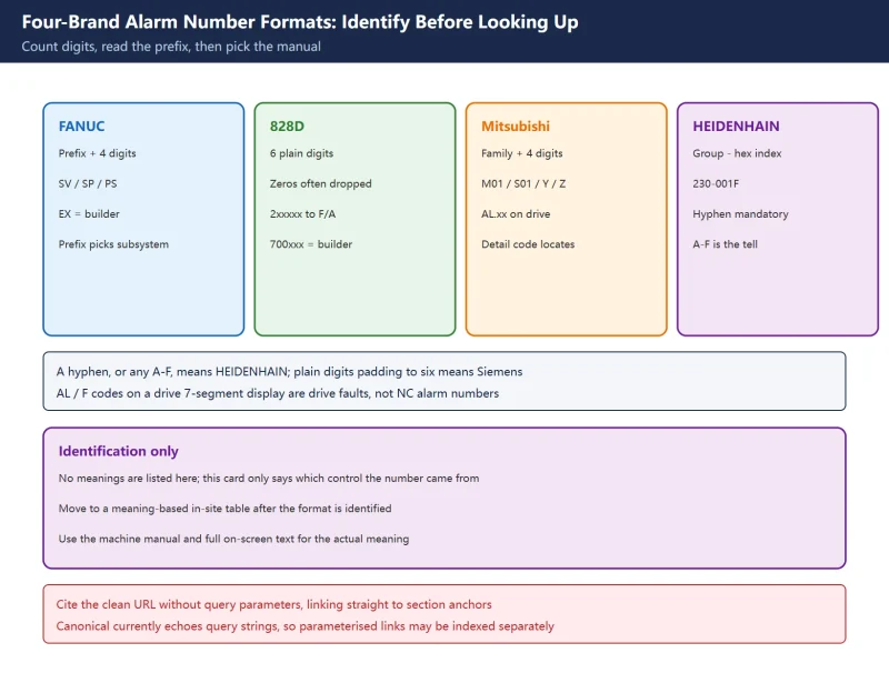
| SP9041 / 9042 / 9046 / 9047 | Position coder one-rotation or A/B phase fault | Follow the alarm table in section 4 |
| Pitch goes wrong at small diameters | Spindle speed changing under G96 constant surface speed | Use G97 fixed RPM for the threading pass and confirm the G50 clamp |
Table 0 First action for six field symptoms
1. Three failure patterns
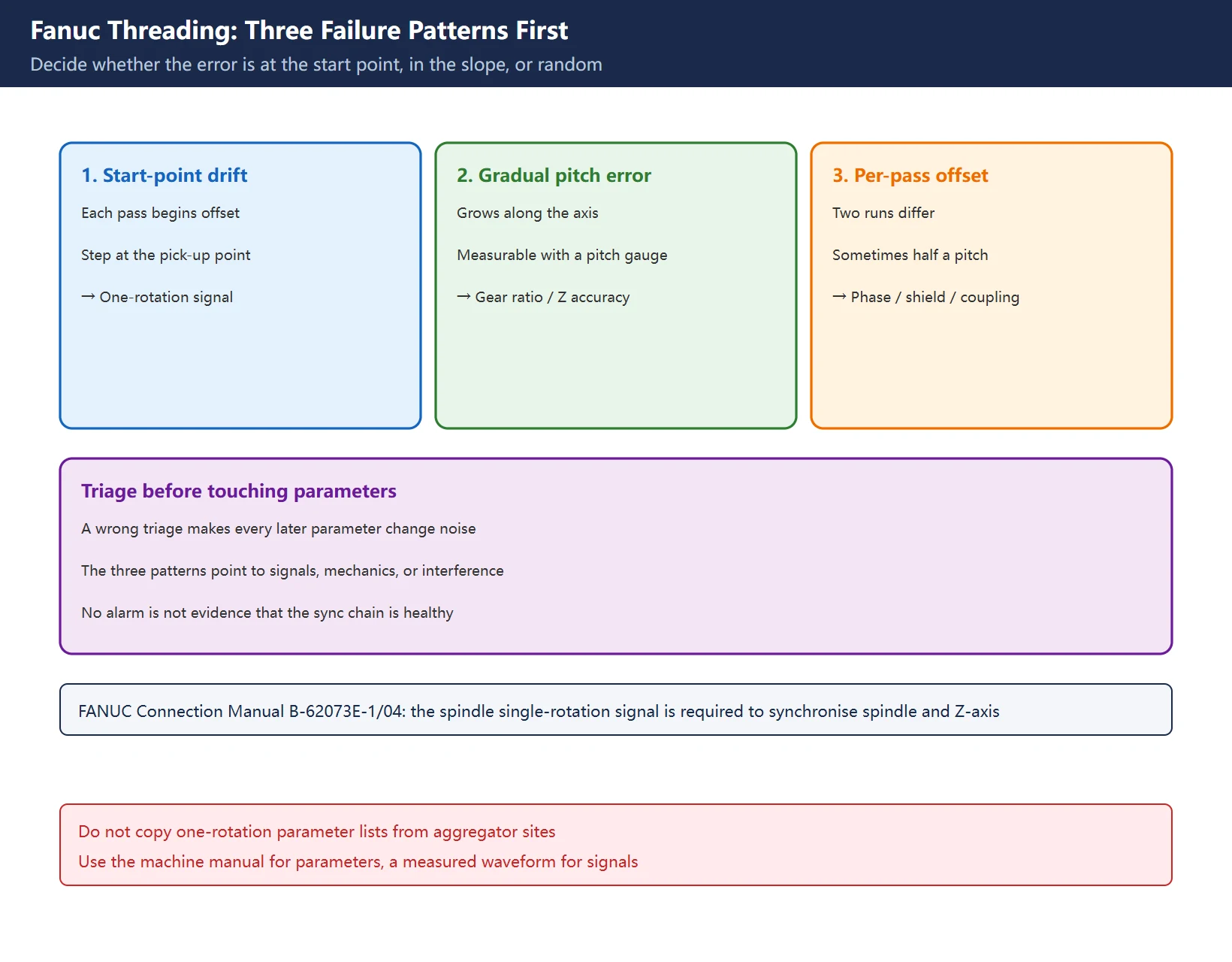
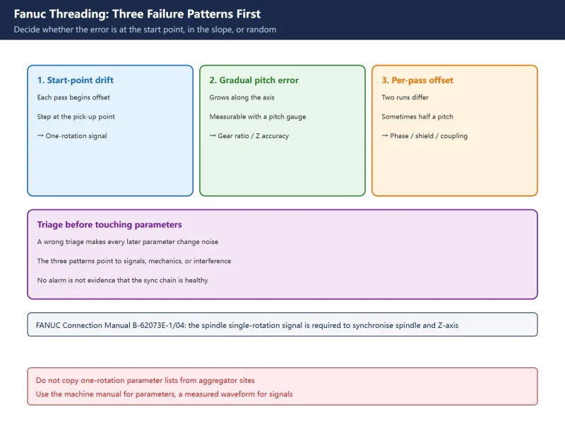
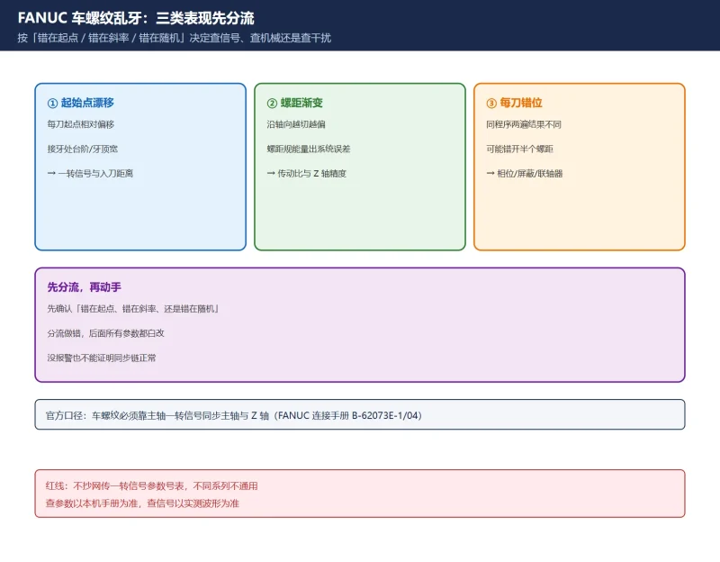
“Bad thread” covers at least three different faults. Treating them as one wastes a whole shift:
- Start-point drift: each pass begins at a slightly different position, leaving a step or a wide crest at the pick-up point. Points to an unstable one-rotation signal arrival time or an approach distance that is not matched to the lead.
- Gradual pitch error: deviation grows along the axis and can be measured with a pitch gauge. Points to a wrong coder-to-spindle gear ratio, Z-axis positioning accuracy, or pitch compensation.
- Per-pass offset: two runs of the same program give different results, sometimes half a pitch apart. Points to one-rotation phase or polarity, shield grounding, power-cable interference, or a slipping coupling.
Rule of thumb: decide first whether the error is at the start point, in the slope, or random. That choice determines whether you investigate signals, mechanics, or interference. Get it wrong and every parameter you change afterwards is noise.
Table 1 Pattern to root-cause domain to verification
| Pattern | Domain | Field verification |
|---|---|---|
| Start-point drift | One-rotation signal / approach distance / accel-decel | SERVO GUIDE capture of one-rotation signal and Z-axis entry delay; air-cut a test thread |
| Gradual pitch error | Coder ratio / Z positioning accuracy / pitch comp | Count Z pulses while hand-rotating the spindle; measure Z positioning with a step gauge or laser |
| Per-pass offset | Phase and polarity / shielding and ground / mechanical slip | Inspect JYA3 shield and routing; check belt, coupling set screws |
On scope: the in-site article on Z-axis backlash and pitch compensation covers mechanical error and how to compensate it; this article covers how the sync chain is established. Backlash does cause a step at the pick-up point, but pitch compensation cannot fix a missing one-rotation signal. FANUC accel-decel time constants affect the entry ramp and sit downstream of this chain; they are a contributor, not the root cause.
2. The spindle sync chain
The FANUC connection manual states it plainly: in threading, the single rotation signal of the spindle is required to synchronize the spindle and the Z-axis. The chain splits into four stages:
- The spindle position coder produces A/B phase pulses (speed and angular position) and a one-rotation signal (one Z pulse per revolution, the phase reference).
- The one-rotation signal reaches the CNC and becomes the only phase reference for the start of every threading pass.
- The NC interpolates in feed per revolution (G99): for each spindle revolution the Z axis travels one lead L, rather than following a feed-per-minute command.
- The Z-axis servo follows: accel-decel, servo delay and backlash all show up in the entry ramp and at the pick-up point.
The manual also gives two constraints that are easy to miss: gear ratio parameters must not be changed during threading or other machining, and when an M:N gear ratio exists between coder and spindle the position of the one-rotation signal shifts with spindle speed (the manual gives the formula). That error is a maximum per pitch and does not accumulate along the thread, provided the spindle runs at constant speed with no servo or accel-decel delay and no mechanical deviation. Older manual versions mention a sampling-smoothing parameter that reduces per-pitch error; that number belongs to Series 15/150 and must not be carried over to the 0i family, so only the principle is given here.
Practical reading: if the measured error accumulates along the length, the problem is most likely Z-axis positioning, gear ratio or the ball screw, not the one-rotation signal. If every pitch is off by roughly the same amount, check the sync chain first.
Table 2 Four stages and their checkpoints
| Stage | What to check | Typical fault |
|---|---|---|
| Coder A/B phase | Clean waveform, pulse count matches nameplate | Slipping coupling, aged belt, contaminated disc |
| One-rotation (Z phase) | Exactly one pulse per rev, fixed angular position | Single broken conductor, lost shield, BZ sensor offset |
| NC feed per revolution | G99 active, lead matches the programmed F | Feed-per-minute used by mistake, wrong F value |
| Z-axis servo following | Entry ramp, backlash, position deviation | Poor accel-decel constants, excessive backlash |
3. G32 / G92 / G76 sync requirements and pull-out
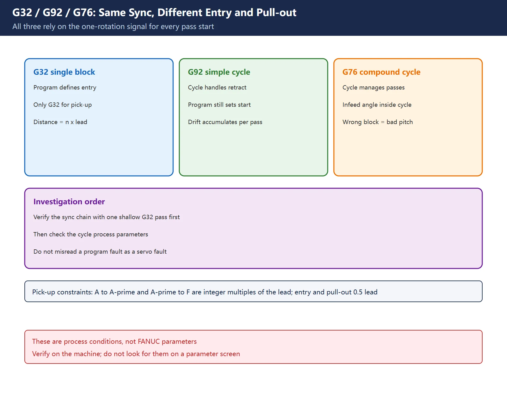
All three commands rely on the same one-rotation reference. What differs is who controls the entry move and the pull-out, and that decides whether you fix the program or the configuration.
Table 3 Division of labour between the three threading commands
| Command | Form | Who controls entry / pull-out | What to check |
|---|---|---|---|
G32 | Single-block constant-lead threading | The program defines the start and end of each G32 segment | Segmented pick-up and angled entry require G32; approach distances must be integer multiples of the lead |
G92 | Simple threading cycle | The cycle handles retraction and return; the program still sets the start point | Each pass gets its own X value; a drifting start point accumulates into the thread form |
G76 | Compound threading cycle | The cycle manages multiple passes, infeed angle and pull-out | A wrong cycle block shows up as “form is fine but pitch is wrong” or uneven passes |
On pick-up threads, a widely cited Chinese field article gives three process constraints worth putting in a work instruction (source is a republished technical article; verify on your machine): distance A to A′ is an integer multiple of the lead; distance A′ to F is an integer multiple of the lead and at least three leads; each Z entry and pull-out move is 0.5 lead, with angled entry at the pick-up point (only possible with G32). These are process conditions, not FANUC parameters — do not go looking for them on a parameter screen.
The same symptom has different first suspects: with
G32, check the program’s approach distance; withG76, check the cycle block and spindle sync. Mixing the two is the fastest route to a false “servo is faulty” verdict.
4. Parameters, signals and how to read the alarms
Start with the conclusion: do not copy a one-rotation parameter list from a forum. The same function has different numbers and bit definitions on 0i-TD, 0i-TF and 31i, and many “3702 / 3708 / 4000-series” lists come from aggregator sites whose own pages contradict each other. The correct method is to see the signal first on SERVO GUIDE or a diagnostic screen, then look up the matching item in the machine’s own parameter manual.
The FANUC 0i-D maintenance manual (B-64305EN/03) appendix is explicit enough to use as a decision table:
Table 4 One-rotation signal alarms (official maintenance manual)
| CNC display | Amplifier display | Official description | Manual's direction |
|---|---|---|---|
SP9041 | SSPA:41 ILLEGAL 1REV SIGN OF POSITION CODER | One-rotation signal of the spindle position coder (connector JYA3) is abnormal | Check and correct the parameter; replace the cable |
SP9042 | SSPA:42 NO 1REV SIGN OF POSITION CODER | One-rotation signal not detected / disconnected | Replace the cable |
SP9043 | SSPA:43 DISCONNECT POSITION CODER DEF. SPEED | Differential speed position coder signal in submodule SW is abnormal | Replace the cable |
SP9046 | SSPA:46 ILLEGAL 1REV SIGN OF SCREW CUT | One-rotation signal during thread cutting is abnormal | Check and correct the parameter, replace the cable, readjust the BZ sensor signal |
SP9047 | SSPA:47 ILLEGAL SIGNAL OF POSITION CODER | A/B phase signal abnormal, or A/B phase and one-rotation signal relationship incorrect (pulse interval mismatch) | Replace the cable; correct cable layout (keep away from power lines) |
SP9027 | SSPA:27 POSITION CODER DISCONNECTED | Position coder disconnected as a whole | Check feedback cable pins and encoder settings |
These numbers map neatly onto the three patterns in section 1: 9042 means “none at all”, 9041 means “present but wrong position or relationship”, 9046 means “only exposed while threading”, 9047 means A/B phase and one-rotation signal do not agree. 9046 is the nastiest: idle running, orientation and normal turning are all fine, and only the threading block fails — easy to misdiagnose as a program bug.
Recommended diagnostic order:
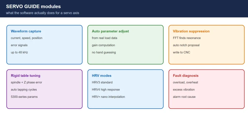
- On the FANUC diagnostic screens and in SERVO GUIDE, watch the one-rotation signal: hand-rotate the spindle one full turn and confirm exactly one clean pulse at a fixed angular position;
- If the waveform breaks when the cable is moved, or only under load / when a particular axis moves, check shield grounding and separation from power leads first (the manual’s explicit direction for 9047);
- If the waveform is stable but the start point still drifts, look at the delay between the one-rotation signal and Z-axis entry, plus the entry ramp accel-decel;
- Only after signals are cleared, measure Z-axis positioning accuracy and backlash / pitch compensation.
On “does a lost one-rotation signal always raise an alarm”: not necessarily. A serial spindle with a position coder will normally report one of the SP90xx alarms above. But analog spindles, external one-revolution switches and machine-builder-specific configurations can produce badly pitched threads with no alarm at all. “No alarm” is not evidence that the sync chain is healthy.
5. G96 constant surface speed and the G50 clamp
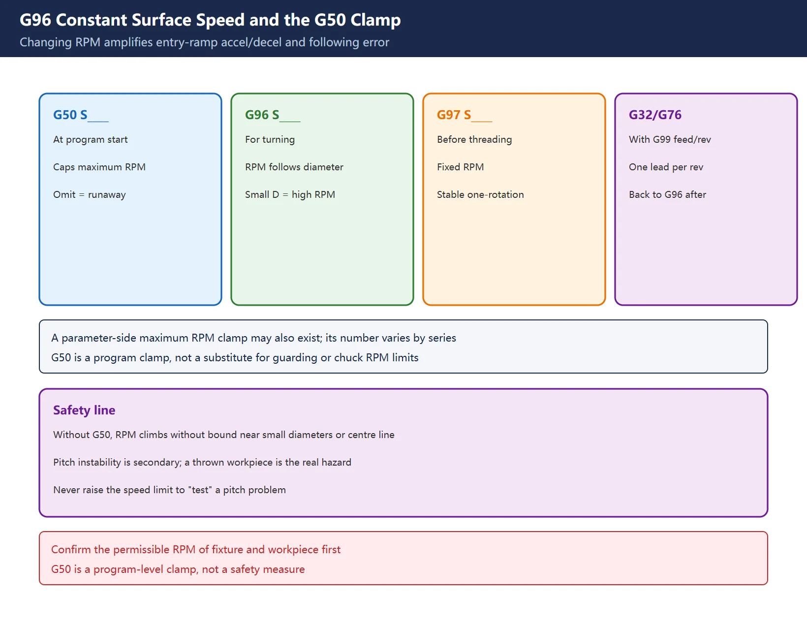
G96 is constant surface speed control: the S word is read in m/min and spindle RPM rises as diameter falls. G97 cancels it and the S word is read in r/min. G50 S____ on a FANUC lathe clamps the maximum spindle speed. Their relationship to threading:
- Threading is synchronised by feed per revolution, so it can in principle run under G96, but spindle speed is continuously changing during the cut. Entry-ramp accel-decel and servo following error are amplified, and the phase relationship between the one-rotation signal and the Z axis is more likely to drift.
- Common field practice is to switch to
G97fixed RPM before the threading block, then return toG96afterwards. - If you use
G96, you must writeG50 S____. Without the clamp, the program reaching a small diameter (especially facing or near centre line) drives RPM up without bound — at best pitch instability, at worst a thrown workpiece or fixture. This is a safety item, not a preference. - Maximum spindle speed may also be clamped on the parameter side; the number range varies by series, so use the machine’s parameter manual rather than an aggregator’s list.
Table 5 Where G96 / G97 / G50 sit in a threading program
| Position | Code | Purpose |
|---|---|---|
| Program start | G50 S____ | Set the maximum RPM clamp before enabling CSS |
| Roughing / finishing | G96 S____ M03 | RPM follows diameter; surface speed stays constant |
| Before the threading block | G97 S____ | Fix RPM, stabilise one-rotation signal and Z sync |
| Threading block | G32 / G92 / G76 with G99 feed per revolution | One lead of Z travel per spindle revolution |
| Back to turning | G96 S____ | Return to CSS (clamp remains active) |
🚨 Safety line:
G50is a program-level clamp, not a substitute for machine guarding, chuck RPM limits or door interlocks. Confirm the permissible RPM of fixture and workpiece before changing the clamp, and never raise the speed limit as a way of “testing” a pitch problem.
6. Do not skip the mechanical and tooling side
If signals and parameters check out and the thread is still wrong, look at mechanics and process. One widely cited field case: a 0i-mate TD with an analog spindle and a 36:92 gear ratio between coder and spindle produced persistent picked-up threads with G92; the fix was a mechanical change — a timing belt giving a 1:1 coder-to-spindle ratio. Another case on a sliding-headstock lathe saw G32/G92/G76 all produce bad threads, with the cause traced to the constant-surface-speed / position-coder matching (that case names a specific bit on a specific model; it is not a general-purpose fix). Both cases make the same point: confirm the mechanical transmission relationship before touching parameters.
- Coder coupling / timing belt: loose set screws or a hardened, slipping belt make the Z pulse angle wander randomly — indistinguishable from a failed coder;
- Z-axis backlash and pitch comp: shows up as a step at the pick-up point and direction-reversal errors; see backlash and pitch compensation;
- Spindle axial float and bearing clearance: one flank of the thread polishes bright as depth of cut changes;
- Tool and setup: wrong centre height, a weak tool holder or a worn insert cause a wrong thread form, not a wrong pitch — do not conflate the two;
- Entry length: leave enough distance for acceleration or the first pitch will always be off; for segmented threads follow the integer-multiple rule in section 3.
Table 6 Four mechanical layers and their criteria
| Layer | Symptom | Quick check |
|---|---|---|
| Coder mechanical drive | Random start-point drift | Hand-rotate and count Z pulses against RPM for a fixed 1:1 |
| Z drive / backlash | Pick-up step, reversal error | Step-gauge forward/reverse measurement |
| Spindle bearings | One flank abnormal under load | Dial indicator on spindle axial/radial float |
| Tool and setup | Wrong flank angle, chatter marks | Centre height, insert condition, tool overhang |
7. Acceptance: one shallow pass, pitch gauge, multi-start split
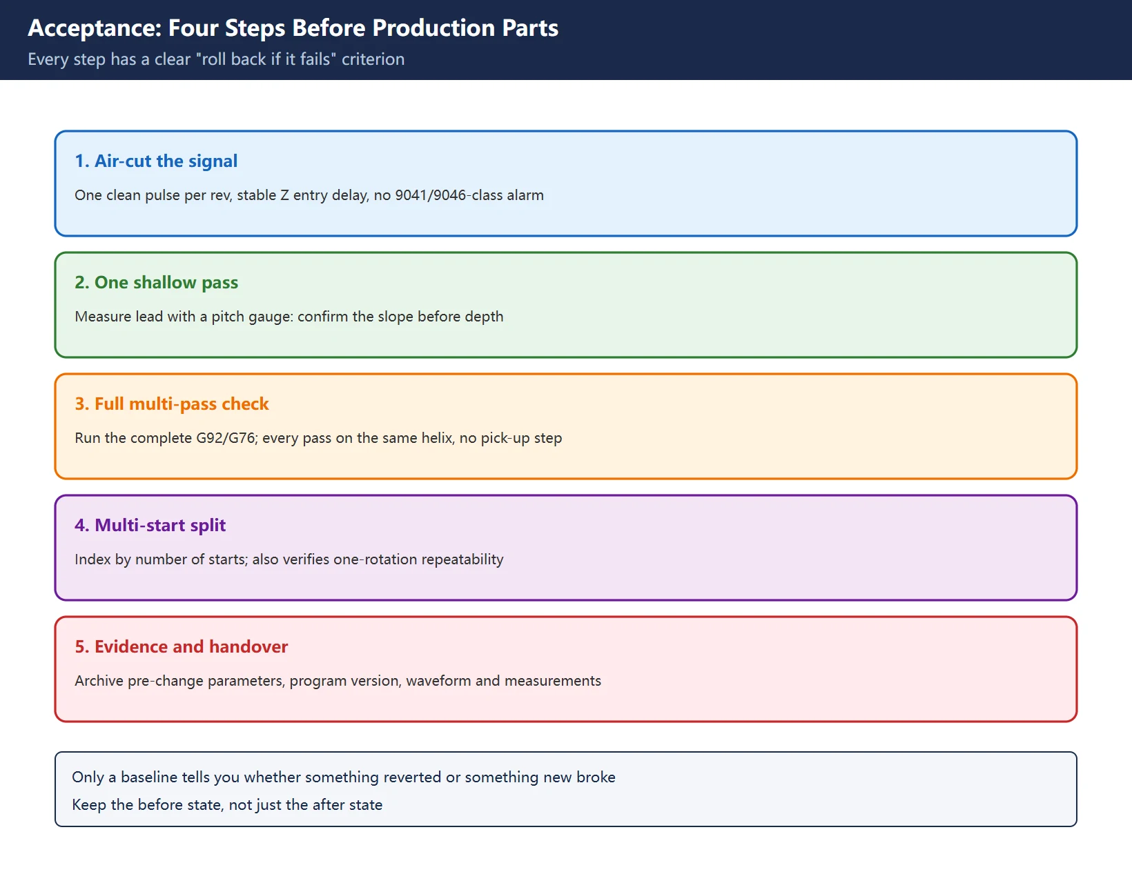
After changing anything, do not go straight to production parts. Use four steps:
- Air-cut the signal: run the program without a workpiece or on scrap; confirm one clean one-rotation signal per revolution, a stable Z-axis entry delay and no 9041/9046-class alarms in SERVO GUIDE;
- One shallow test pass: cut a single light pass and measure the lead with a pitch gauge or thread micrometer — confirm the slope before discussing depth;
- Full multi-pass check: run the complete
G92/G76and check that every pass sits on the same helix with no step at the pick-up point; - Multi-start split: index by the number of starts and cut again, confirming the start point matches the one-rotation phase. This step also verifies one-rotation repeatability.
Keep the evidence: archive the pre-change parameters, program version, one-rotation waveform capture and test-cut measurements together (parameter and ladder export). Next time the thread goes bad, only a baseline tells you whether something reverted or something new broke.
🚨 This article deliberately omits a copy-and-paste one-rotation parameter table. The number ranges circulating online come mostly from aggregators and are not portable between 0i, 31i and 0i-F; a wrong entry can cost the spindle its sync. Use the machine’s own manual for parameters and a measured waveform for signals.
Frequently Asked Questions
Do G32 and G76 pitch errors have the same cause?
The sync principle is identical, but the investigation priority differs. Both rely on the spindle one-rotation signal to set each pass’s start point, so a lost signal, phase jitter or a wrong coder gear ratio will upset G32, G92 and G76 together. With G32, however, the entry point and pull-out are written entirely in the program, so errors usually come from a pick-up distance that is not an integer multiple of the lead, or too short an acceleration ramp. With G76, the cycle manages multiple passes and pull-out internally, so trouble is more often in the cycle parameter block, the feed-per-revolution mode and the spindle sync configuration. The efficient order is to verify the sync chain with a single shallow G32 pass first, then go back and check the cycle’s process parameters.
Does a lost one-rotation signal always raise an alarm?
Not always; it depends on the spindle configuration. A serial spindle with a position coder normally reports one of the alarms in the FANUC 0i-D maintenance manual (B-64305EN/03): SP9042 for a one-rotation signal not detected / disconnected, SP9041 for an abnormal one-rotation signal, SP9046 specifically for an abnormal signal during thread cutting, and SP9047 for an incorrect A/B-phase to one-rotation relationship. But analog spindles, external one-revolution switches and machine-builder-specific configurations can produce badly pitched threads with no alarm at all. “No alarm” does not prove the sync chain is healthy — hand-rotate the spindle one full turn on SERVO GUIDE or a diagnostic screen and confirm exactly one pulse at a fixed angular position.
Why does threading under G96 need a G50 speed clamp?
Because G96 automatically raises spindle RPM as diameter decreases, and G50 S____ is the FANUC lathe’s program-level command that caps maximum RPM. Without it, RPM climbs without bound as the tool approaches a small diameter or the centre line — a runaway-speed safety hazard as well as a source of pitch instability, since entry-ramp accel-decel and servo following error are amplified. Safe field practice is: write G50 S____ at the start of the program, use G96 for turning, switch to G97 fixed RPM before the threading block, then return to G96 afterwards. There may also be a parameter-side maximum RPM clamp whose number varies by series; use the parameter manual shipped with the machine.
Last updated: 2026-11-08
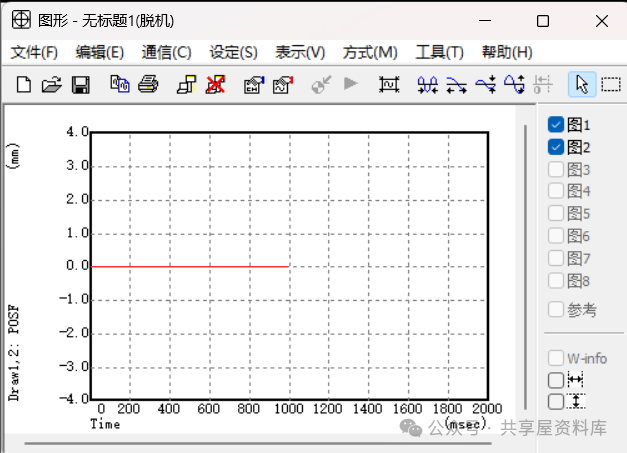
FANUC SERVO GUIDE: Waveform Analysis
Where to go next
- FANUC Troubleshooting — the full guide library: alarms, diagnosis numbers, servo, spindle, PMC and electrical faults, organised by symptom.
- CNC Repair Tools — which instrument measures what: multimeters, clamp meters, insulation testers and oscilloscopes, with the specification that actually matters.
- Remote Technical Support — have the readings reviewed with you: alarm reverse lookup, PMC ladder analysis and servo tuning advice by call. Repair companies and integrators welcome.
Read the guide, get the right instrument, or walk the diagnosis through with someone — pick whichever you need.
The original Chinese version — same procedure, with the full field notes.




















暂无评论内容