


Sequence and electrical details here come from the official FANUC B-65162E/03-10, “Signal processing and parameter setting for Machine Protection Function at Power Failure”, chapter 3 “Gravity-axis Electrical Brake Function at Power Failure”, plus the Chinese engineering article “Analysis and Design of Vertical-Axis Anti-Drop for CNC Machine Tools” on brake power supplies and timing. 🚨 Parameter numbers vary by series and software version; the numbers in this article only illustrate the manual’s grouping. Use the parameter manual shipped with the machine and take a parameter and ladder export first.
30-second triage
| Symptom | First suspect | First action |
|---|---|---|
| Z sinks on E-stop / power loss | Brake too slow, torque removed first | Log the drop distance, check sequence and Td |
| Free fall after power loss | Brake did not engage, power circuit open | Check dedicated 24V, relay contacts, coil |
| Brake released but axis will not move | Servo not excited, SA/F0.6 absent, interlock | Check servo ready and ladder release conditions |
| Brief dip at power-up | Release order reversed (brake before excitation) | Servo ON must come before brake release |
| Drops only under load / at one position | Brake wear, insufficient counterbalance | Check disc gap and balance system |
| Worse after a motor swap | Brake control settings not re-verified | Re-check BRKC and timers per section 4 |
Table 0 First action for six symptoms
1. Why a gravity axis drops: the brake is power-off engaged
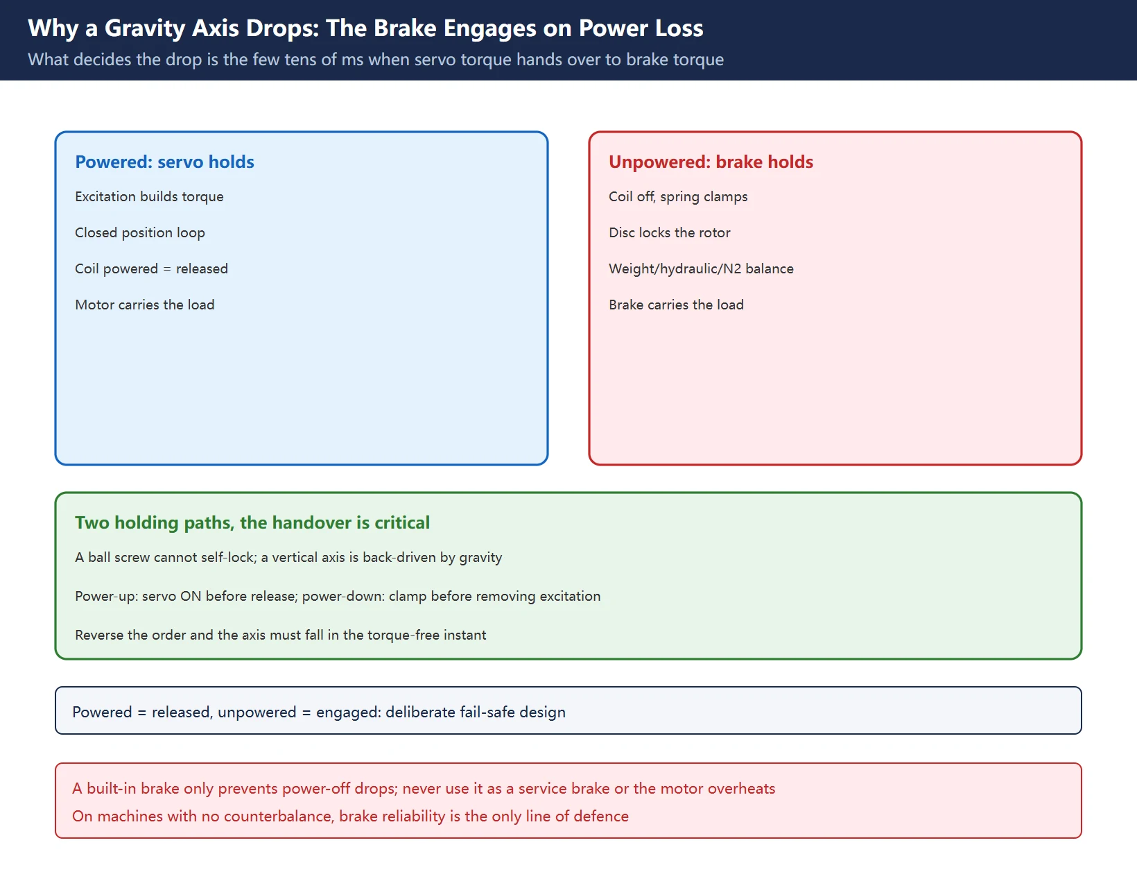
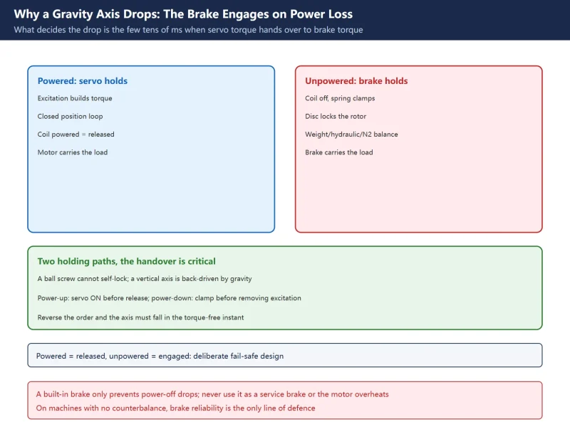
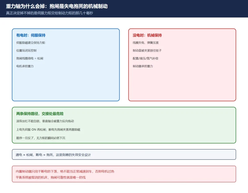
A ball screw and nut cannot self-lock. A vertical axis (Z on a VMC, Y on an HMC) is back-driven by the headstock weight once servo power is gone. Every machine therefore needs two holding mechanisms:
- Powered: the servo motor is excited and its holding torque, under closed-loop position control, carries the load;
- Unpowered: the motor’s built-in electromagnetic brake engages on loss of power — the coil de-energises, a spring pushes the armature and clamps the brake disc against the end shield, locking the rotor by friction.
The Chinese design article states the principle plainly: energise the coil and the armature pulls in against the spring, releasing the disc; remove power and the spring clamps it. Note the direction: powered = released, unpowered = engaged. That is deliberate fail-safe design.
🚨 An often-ignored rule: a built-in motor brake exists only to prevent a gravity axis from dropping when servo power is removed. It must never be used as a normal service brake for deceleration, or the motor will overheat. A brake is a parking lock, not a stopping brake.
Table 1 Division of labour between the two holding paths
| State | What holds the axis | Risk |
|---|---|---|
| Normal run (powered) | Servo excitation + position loop | Poor gain, wrong inertia ratio |
| E-stop / power-loss instant | Handover between the two | Tens of ms of mismatch causes a drop |
| Fully unpowered | Brake disc + counterbalance | Wear, air gap, low voltage |
| Balance system | Weight / hydraulic / nitrogen | Insufficient compensation amplifies drop |
Counterbalance (weight, hydraulic, nitrogen) reduces the forward/reverse load difference and the axial gravity load on the screw. Many newer machines drop the hydraulic balance for simplicity and rely on a braked servo motor — which makes brake reliability the only line of defence. On the relationship to servo gain tuning order and inertia ratio identification: poor gain shows up as weak position holding under load, but it is not the cause of a power-loss drop. Do not conflate the two.
2. Power-up and power-down sequence must be exact reverses
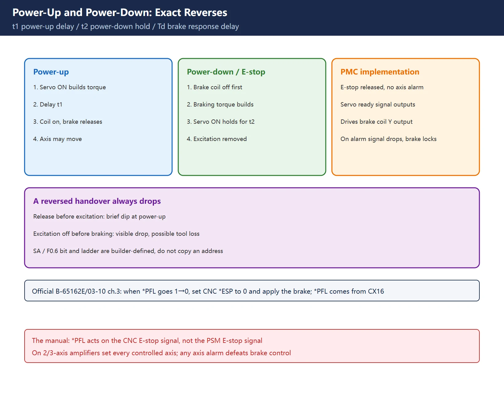
This is the core diagram of the whole article. The Chinese design material gives the order:
Power-up: switch the servo drive ON first so the motor builds holding torque → delay t1 → energise the brake coil to release → the axis may move.
Power-down / E-stop: the brake coil de-energises first and produces braking torque → servo ON stays active for a further t2 (holding torque still present) → only after t2 is servo excitation removed. In other words, clamp the axis with the brake before removing motor torque.
Reverse either handover and the axis must drop: release the brake before excitation and the axis falls in the torque-free instant; remove excitation before braking and it falls further.
Table 2 Two sequence stages and their criteria
| Stage | Correct order | Consequence if reversed |
|---|---|---|
| Power-up | Servo ON → t1 → release → move | Brief dip at power-up |
| Power-down / E-stop | Brake engages → t2 → excitation off | Visible drop, possible tool loss |
| On servo alarm | Alarm → release condition drops → brake locks | Brake not locked = free fall |
Typical PMC implementation: once E-stop is released, the servo is working and no axis has an alarm, the control outputs the servo ready signal (commonly F0.6, i.e. SA) to the PMC, and the ladder uses it to drive the brake coil Y output. On a servo alarm that signal disappears and the brake coil de-energises, locking the axis. 🚨 The exact bit designation and ladder implementation for “SA / F0.6” are defined by the machine builder — confirm them in the machine’s PMC signal list and ladder, do not copy an address.
3. Electrical: brake 24V, surge suppression and relay contacts
The Chinese design article is very specific about the power circuit, and every point bears directly on whether the axis drops:
- FANUC βis series built-in brakes use DC 24V, typically from a transformer plus full-wave diode rectifier. Allowing for rectifier and cable drop, the transformer secondary is about AC 29Vrms; confirm the voltage at the brake is within ±10%. Older motors are not necessarily 24V — check the nameplate;
- 🚨 Do not share the CNC / servo amplifier 24V supply. At power loss you want CNC control power to last as long as possible (so the brake logic can complete), but the brake supply to collapse as fast as possible (for a quick stop). The two requirements are opposite, and the brake circuit should not have a large smoothing capacitor;
- The surge voltage when the coil de-energises shortens relay contact life — use adequately rated contacts plus a spark killer / surge absorber;
- Put the brake switching relay on the DC side. On the AC side (between transformer secondary and rectifier) current needs time to return through the rectifier diodes, delaying brake action and increasing drop distance directly;
- Choose a fast relay (the article cites ~10 ms) and drive its coil from a higher-voltage mains-derived supply to speed it up;
- CNC and amplifier control power hold-up must outlast the brake response time; extend it with a UPS if necessary, or the logic loses power before it finishes;
- Some machines have a brake release / engaged confirmation X point, builder-defined, used in the ladder as a condition for allowing axis motion. Machines without such a switch rely on timing — do not assume one exists. For contact rating and selection see safety relay component selection; for circuit notation see reading machine electrical drawings.
Table 3 Four electrical checkpoints
| Layer | What to check | If abnormal |
|---|---|---|
| Supply | Dedicated DC24V, ±10%, no large capacitor | Low voltage → will not release or releases slowly |
| Switching position | Relay on the DC side | AC-side relay → delayed brake |
| Contact protection | Spark killer / surge absorber, contact rating | Burnt contacts, unreliable action |
| Confirmation | Release / engaged X point, if fitted | Condition unmet → axis will not move |
4. PMC and parameters: the official power-failure brake function
Official FANUC B-65162E/03-10, chapter 3 “Gravity-axis Electrical Brake Function at Power Failure”, defines this as a power-failure protection function: when mains power fails, the vertical axis position is held electrically until its mechanical brake engages, preventing the axis from dropping. The manual’s procedure:
- Set the parameters of the Brake Control Function (a basic servo function);
- When the power failure detection signal
*PFLchanges from 1 to 0, set the CNC emergency stop signal*ESPto 0 and put the vertical-axis brake on simultaneously; *PFLcomes from the CX16 connector on the Power Failure Backup Module;- 🚨 The manual explicitly notes: the signal driven by
*PFLis the CNC emergency stop signal, not the PSM (power supply module) emergency stop signal; - Parameter settings:
BRKC = 1(enable the brake control function) and Brake control timer = Td, the delay until the brake starts operating — the manual gives an order of magnitude of about 100 ms; - The manual also warns: when brake control is applied to a two- or three-axis amplifier, set it for all controlled axes; if any axis generates an alarm, brake control does not operate effectively.
Table 4 Official manual parameter grouping (illustrative only, not values to copy)
| Series | BRKC | Brake control timer |
|---|---|---|
| FS15i / FS15-A / FS15-B | No.1883 #6 | No.1976 |
| FS16i / 18i / 21i, FS16/18/20, Power Mate | No.2005 #6 | No.2083 |
| FS0-C | No.8X05 #6 | No.8X83 |
🚨 This table exists only to show that parameter numbers differ by series. It comes from a 1999 supplement and must not be applied directly to 0i-F / 31i and newer controls. Combinations circulating in third-party Chinese notes such as
2210#5/#6E-stop delay or2204#7are not used here; only the timing principle is kept — t3 (E-stop active) must be later than t2 (delayed MCC off), and t2 later than t1 (mechanical clamp). Look up numbers in the machine’s own parameter manual, and follow PWE write enable with a backup before editing.
On “vertical-axis flags” and “power-loss drop monitoring”: implementations and names vary by series and builder, and there is no universal parameter number to copy. The workable field method is to log the drop distance after every E-stop / power-loss event as a baseline (the Chinese article gives an order of 20 µm of mechanical play at 10 mm lead) and watch the trend. Some builders also implement a “gravity-axis lift at E-stop” function that nudges the axis up before clamping, to cancel brake play.
5. Four-layer diagnosis: mechanics first, servo last
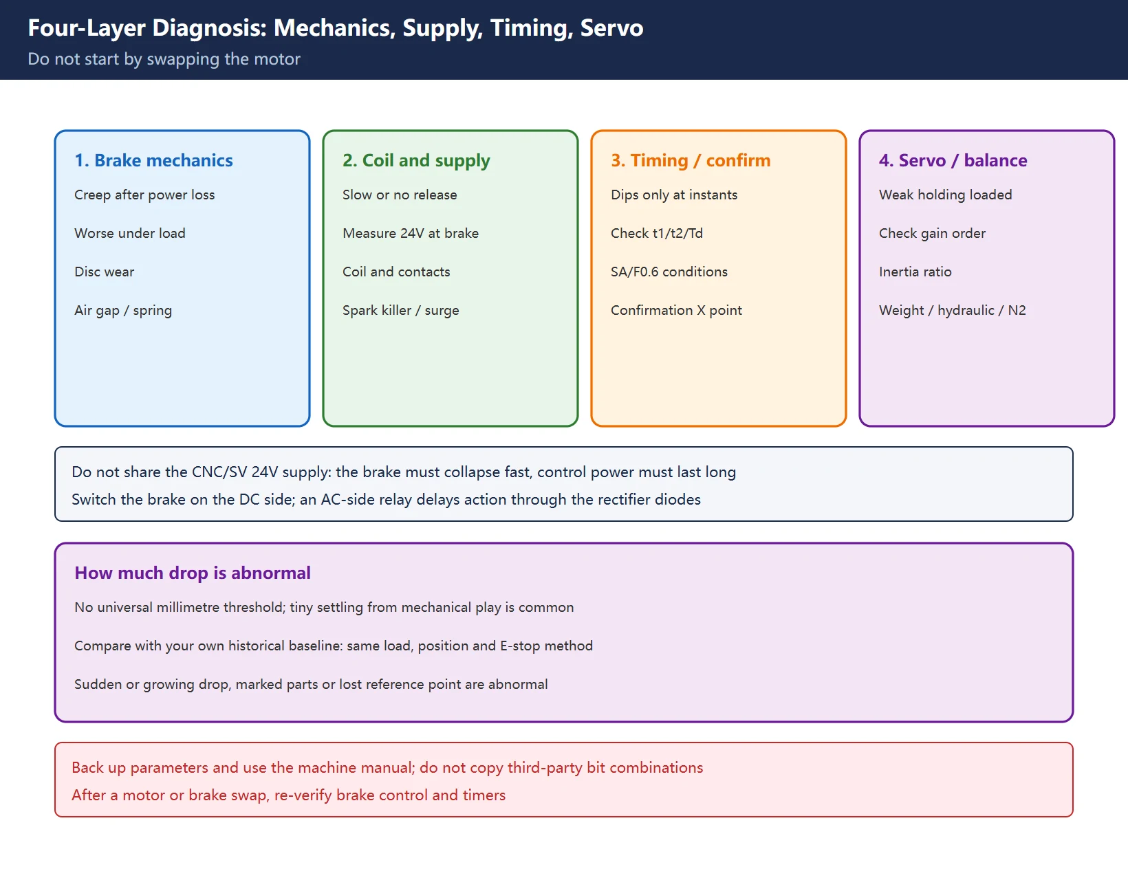
Work through “mechanics → electrical → timing → servo” so you do not start by swapping a motor:
Table 5 Four layers and their criteria
On “how much drop is abnormal”: there is no universal millimetre threshold across machine models. Brakes have mechanical play, so a tiny settling after power loss is common, and many machines simply require a reference-point return at power-up to cancel it. The workable criterion is comparison with your own machine’s historical baseline: same load, same position, same E-stop method — a sudden or progressively increasing drop is abnormal. Also check whether the workpiece or tool was marked and whether the reference point was lost. Do not adopt a forum’s “allowable X microns” as an acceptance standard.
6. Priority when E-stop, power loss and amplifier alarms overlap
Field cases are rarely a simple “bad brake”; several events usually overlap:
- People first, then machine: confirm personnel and workpiece safety and get mechanical support in place before repeatedly powering up to test;
- Identify the trigger: did the operator press E-stop, did mains fail, or did an axis amplifier alarm? The sequence starts from a different point in each case — on E-stop the CNC logic is still alive, on sudden mains loss everything depends on control-power hold-up and
*PFLdetection; - Clear the E-stop chain first: if
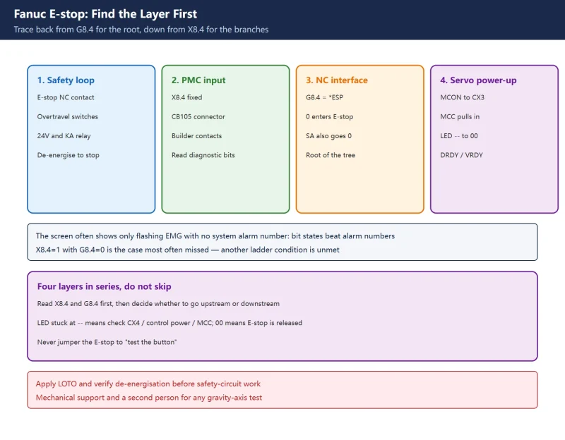
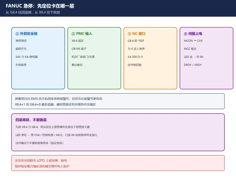
*ESP/G8.4states are wrong, the brake release condition can never be satisfied — see the companion article on the FANUC E-stop circuit and the safety integrated topic; - Amplifier alarms on top: the official manual states that brake control does not work effectively if any controlled axis alarms, so on two/three-axis amplifiers clear the alarm before judging the brake. For parameter and wiring checks after an amplifier swap see servo amplifier replacement;
- Then return to the four layers: mechanics → supply → timing → servo.
Newer machines add one more layer: when E-stop is tied to STO / SS1 safety functions, whether torque is removed after a controlled stop or immediately determines whether the brake has time to clamp. Changing a safety configuration is a safety-design change and must be assessed by the machine builder or qualified personnel — never extend the torque-removal delay yourself just to stop the drop.
7. Safety rules and acceptance
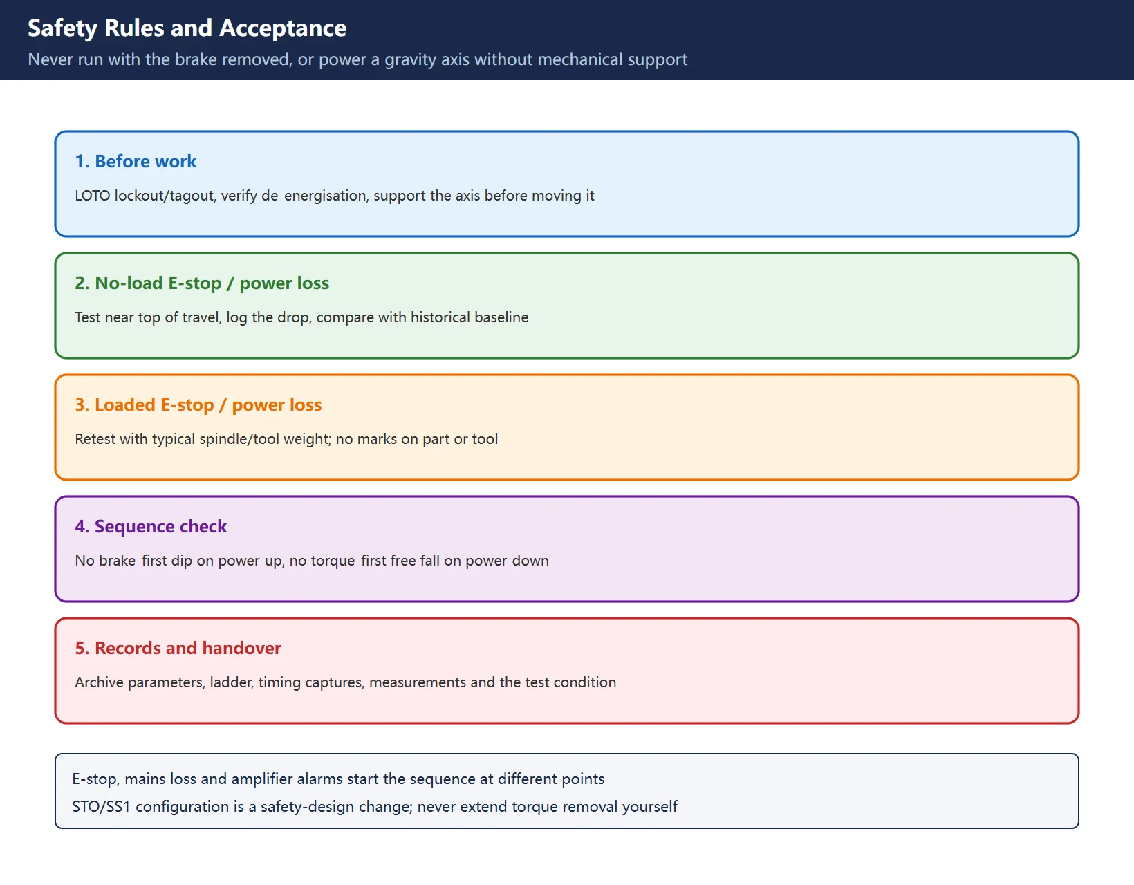
Never run the machine with the brake removed, and never power up or jog a gravity axis while the brake is held released without mechanical support. Once a vertical axis loses its holding means, a falling headstock can injure people and destroy parts.
- Start any brake work with LOTO (lockout/tagout) and verified de-energisation; if the axis must be moved, provide mechanical support first, have a second person watching, use single block at low feed, and keep a hand near the E-stop;
- Acceptance order: no load, E-stop and power-loss tests near the top of travel → log the drop → repeat with typical spindle/tool weight → verify both triggers (E-stop and simulated power loss);
- Also confirm: no “brake first” dip at power-up, no “torque first” free fall at power-down, reference point and work offsets intact, no new amplifier alarms;
- Archive the pre-change parameters, ladder, timing captures and measurements together (parameter and ladder export);
- After replacing a servo motor or brake, re-verify the brake control function and timers instead of assuming the old values still apply.
Table 6 Safety lines and acceptance checklist
| Item | Pass criterion |
|---|---|
| Mechanical support | Support in place before testing, personnel clear, supervision present |
| No-load E-stop / power loss | Drop matches historical baseline, no abnormal noise |
| Loaded E-stop / power loss | Same condition retest, no marks on workpiece or tool |
| Power-up order | No “brake first” instant dip |
| Power-down order | No “torque removed first” free fall |
| Records and handover | Parameters, ladder, timing, measurements complete |
Frequently Asked Questions
Is a small Z-axis drop at power loss normal, and how much is abnormal?
Brakes have mechanical play, so a tiny settling after power loss is common — many machines simply require a reference-point return at power-up to cancel it, and the Chinese design material cites roughly 20 µm of play at a 10 mm lead. But there is no universal millimetre threshold across machine models; do not adopt a forum figure as an acceptance standard. The workable criterion is comparison with your own machine’s historical baseline under the same load, position and E-stop method: a sudden or progressively increasing drop is abnormal, as is a marked workpiece/tool or a lost reference point. If the drop is visible, follow the four-layer diagnosis in section 5 — brake wear, 24V supply and timing — before touching parameters.
The brake has released but the axis still will not move. Where first?
Do not suspect the mechanical brake; follow the release-condition chain. Is the SA / servo ready signal (commonly F0.6; confirm the bit in the machine’s PMC signal list) actually output? Is the servo excited with no axis alarms? Are all other interlocks in series with the brake Y output — door, clamp, pressure, and the release / engaged confirmation X point — satisfied? On machines with a confirmation X point that switch is the most common blocker: the coil is energised and the disc released, but without the confirmation the ladder will not permit axis motion. After that, go back to the PMC diagnostic screen and check whether *ESP / G8.4 have released, whether MCC pulled in, and whether the amplifier LED shows -- or 00. Also remember that the brake plays no part in normal running — treating it as a service brake will send you in the wrong direction.
After replacing a servo motor, do the brake timings need to be reset?
They must be re-verified, not assumed. A new motor or brake can have a different coil voltage, response time and mechanical play, while the whole sequence depends on the t1 power-up delay, t2 power-down hold and Td brake delay of the official B-65162E/03-10 Brake Control Function (BRKC and the Brake control timer). That manual explicitly shows different parameter numbers by series (1883#6/1976, 2005#6/2083, 8X05#6/8X83 are grouping examples only), requires every controlled axis to be set on two/three-axis amplifiers, and warns that any axis alarm makes brake control ineffective. Procedure: back up parameters and ladder, verify each item against the machine’s own parameter manual, then repeat no-load and loaded E-stop / power-loss tests per section 7 and compare the drop with the historical baseline. Do not copy bit combinations from online notes, and never run these tests without mechanical support.
Last updated: 2026-11-08
Fanuc Emergency Stop Circuit: *ESP, G8.4 and X8.4
Where to go next
- FANUC Troubleshooting — the full guide library: alarms, diagnosis numbers, servo, spindle, PMC and electrical faults, organised by symptom.
- CNC Repair Tools — which instrument measures what: multimeters, clamp meters, insulation testers and oscilloscopes, with the specification that actually matters.
- Remote Technical Support — have the readings reviewed with you: alarm reverse lookup, PMC ladder analysis and servo tuning advice by call. Repair companies and integrators welcome.
Read the guide, get the right instrument, or walk the diagnosis through with someone — pick whichever you need.
The original Chinese version — same procedure, with the full field notes.






















暂无评论内容