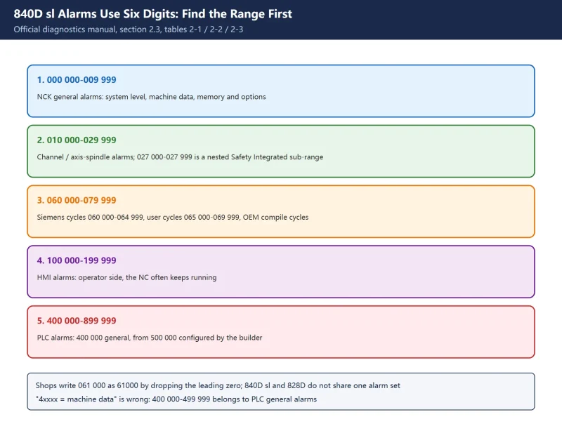



Sources: NCK / HMI / SINAMICS ranges come from the official *SINUMERIK 840D sl, SINAMICS S120 Alarms Diagnostics Manual*, section “2.3 Alarm number ranges”, tables 2-1 / 2-2 / 2-3. PLC ranges come from the official *SINUMERIK 840D/840Di/810D Diagnostics Guide*, table 1-4. 🚨 Reserved ranges and subdivisions vary by software version; always use the machine’s own manual and the full on-screen message for the actual text and cancel criterion. This page gives structure, not alarm texts.
30-second triage
| What you see | Owner | First move |
|---|---|---|
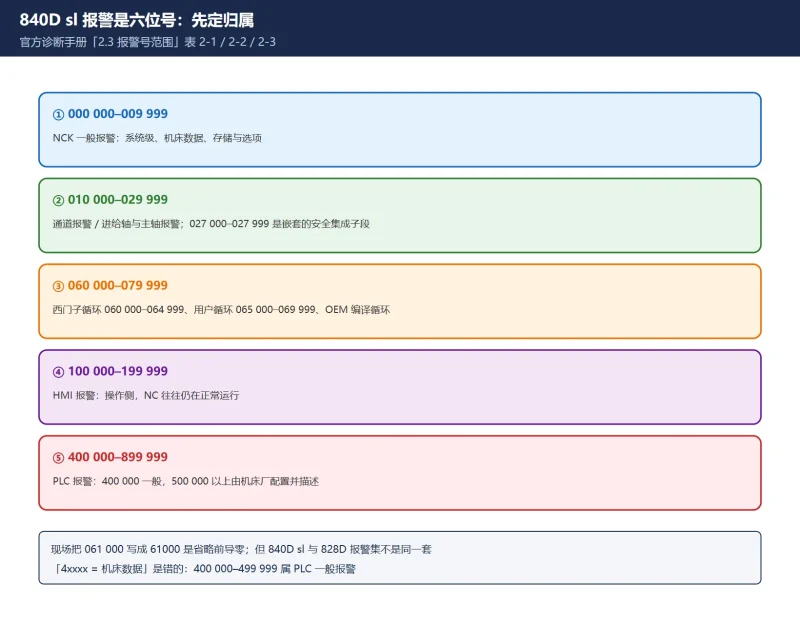
0xx xxx | NCK alarm | 000 000-009 999 general / 010 000-019 999 channel / 020 000-029 999 axis and spindle |
060 xxx–069 xxx | Cycle alarm | Siemens cycles 060 000-064 999; user cycles 065 000-069 999 |
1xx xxx | HMI alarm | 100 000-199 999, operator side; the NC may still be running |
2xx xxx | SINAMICS / drive | Manual mapping ranges; the drive itself shows F / A codes |
400 000–499 999 | PLC general alarm | Not “machine data”, and not a four-digit 828D number |
700 000–799 999 | Machine builder user area | Siemens has no text for this range |
Table 0 Six-digit range, owner and first move
1. Count the digits: 840D sl uses six, not the shortened 828D form
840D sl alarm numbers are six digits, written in the manuals in groups such as 000 000 - 009 999 or 100 000 - 100 999. In the shop, and on many web pages, the leading zero is dropped, so 060000 becomes 60000 and 061000 becomes 61000.
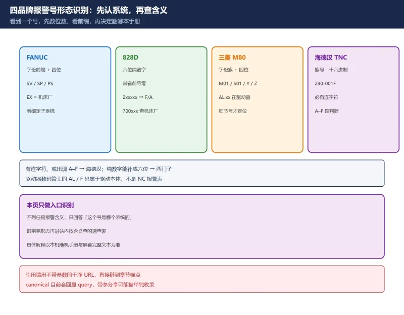
That is the same shorthand habit explained in our earlier article on 828D cycle alarms 61000 / 62000: both are really numbers in the 06xxxx six-digit block. ⚠️ It does not mean 840D sl and 828D share one alarm set. Software versions, drives and options differ, and a number that exists on one control may have no text at all on the other. Lists that describe 840D sl as 0xxx / 2xxxx / 4xxxx have mixed in the 828D shorthand and will send you to the wrong manual.
🚨 Correction 1: the common claim that “4xxxx means machine data” is wrong. In the six-digit 840D sl / 840D scheme, 400 000 - 499 999 is PLC general alarms. Alarms tied to machine data mostly live in the NCK general block 000 000 - 009 999 and the functional blocks.
Table 1 Shop shorthand versus the official six-digit number
| Shop form | Official range | Correct reading |
|---|---|---|
61000 / 62000 | 061 000 / 062 000 | Siemens cycle alarms |
400000 PLC STOP | 400 000 | PLC general alarm, not machine data |
700123 | 700 123 | Builder user area, no Siemens text |
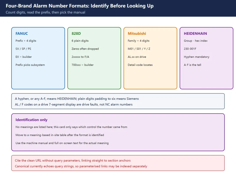
F30001 | Drive fault code | Not a six-digit alarm number; SINAMICS |
2. NCK alarms 000 000-099 999: general, channel, axis and functional
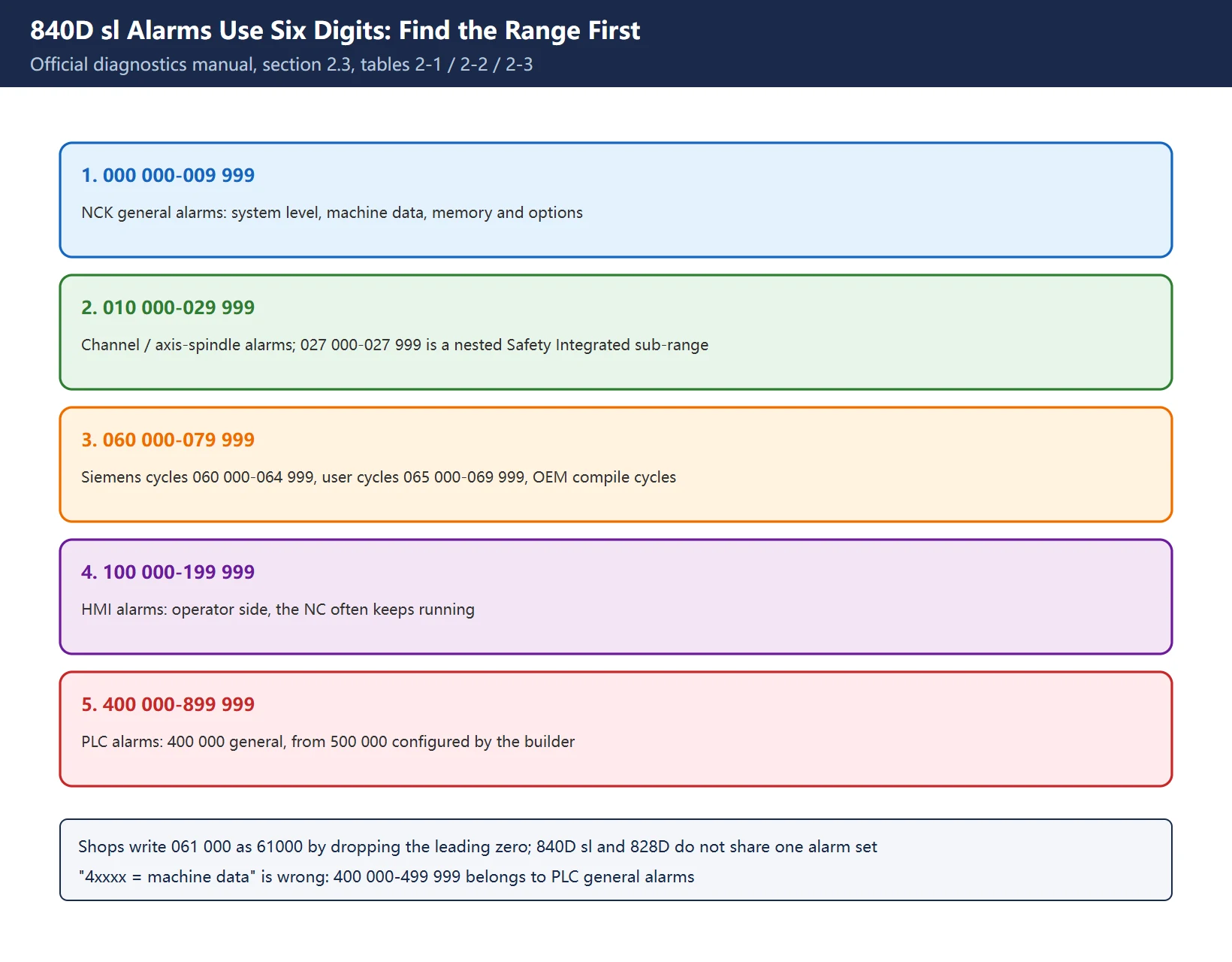
Table 2-1 of the official manual is the one worth memorising:
| Range | Official category | What it means on site |
|---|---|---|
000 000 - 009 999 | General alarms | System level, machine data, memory and options; usually the serious ones |
010 000 - 019 999 | Channel alarms | Programming, operating mode, limits; usually program or operator side |
020 000 - 029 999 | Axis / spindle alarms | Encoders, monitoring, clamping; the maintenance battleground |
027 000 - 027 999 | Safety Integrated alarms | Dedicated sub-range nested inside 020 000-029 999 |
030 000 - 099 999 | Functional alarms | Broad block with further subdivisions |
040 000 - 059 999 | Reserved | Marked “Reserved” in the manual; do not invent meanings |
🚨 Note that 027 000 - 027 999 is nested inside the axis/spindle block, not a seventh parallel area. Treat a 027xxx alarm as a safety-function matter first; do not go straight to gain tuning. See our 840D sl safety-integrated notes for the field differences.
Table 2 Official NCK ranges and their field meaning
Read the alarm list in time order. Open the Diagnosis area and start from the oldest entry. The message on screen is usually the last link in a chain: an encoder hardware alarm, then a following-error alarm, then a channel stop, then a PLC interlock — and the operator quotes only the final line. Our CNC alarm number format card answers “which control is this from”; this page answers “which range inside this control”, so the two are successive steps.
3. Cycle alarms 060 000-079 999: why 61000 and 62000 belong together
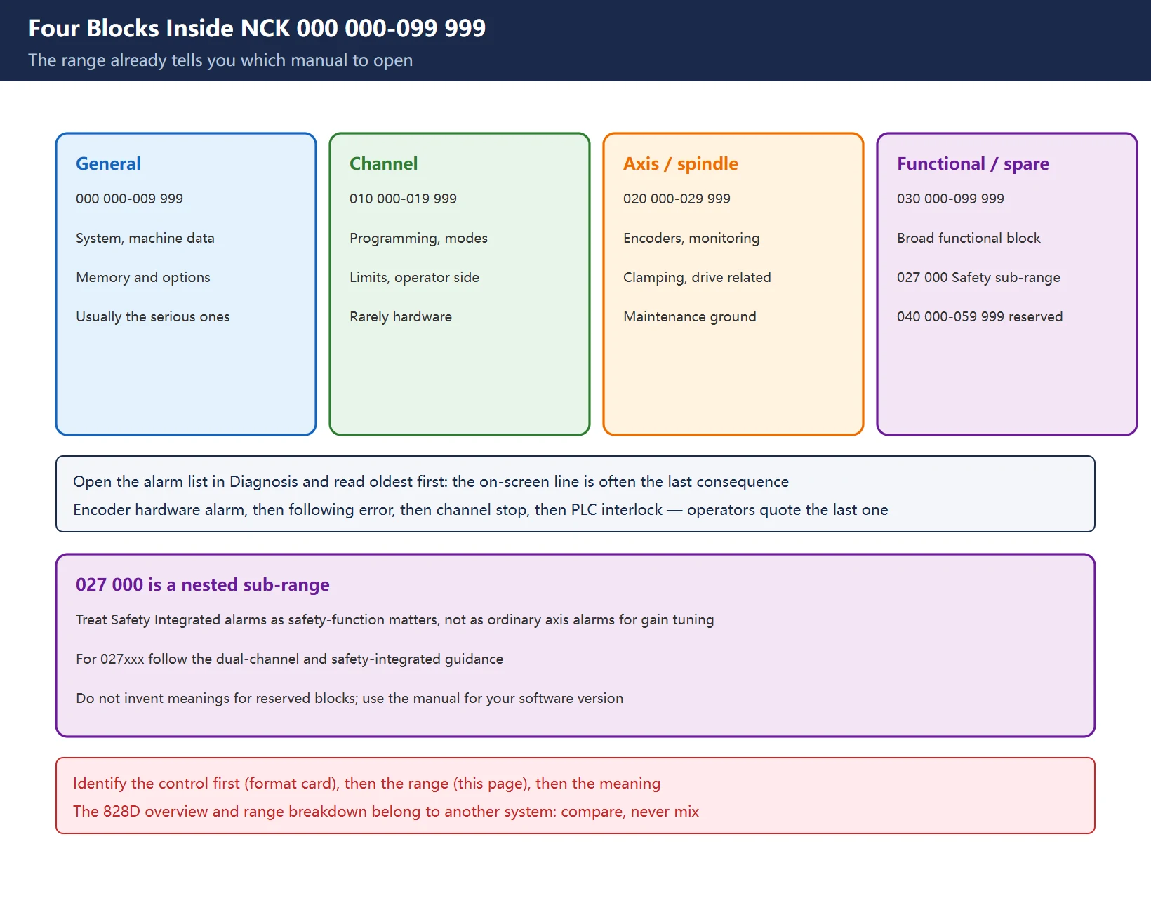
| Range | Official category | Who writes the text |
|---|---|---|
060 000 - 064 999 | Siemens cycle alarms | Siemens standard cycles (CYCLE81 / CYCLE83 family) |
065 000 - 069 999 | User cycle alarms | Triggered by SETAL etc.; builder or programmer |
070 000 - 079 999 | Compile cycles, manufacturer and OEM | Machine builder compile cycles |
080 000 - 084 999 | Message texts for Siemens cycles | Mostly messages rather than faults |
083 000 - 084 999 | Messages for measuring cycles | Measurement-cycle information |
So the shop terms 61000 (= 061 000) and 62000 (= 062 000) both sit in the Siemens standard cycle alarm block — not “61000 is tooling, 62000 is the magazine”. That misreading is corrected in detail in 828D cycle alarms 61000 / 62000. For a cycle alarm, check the cycle call parameters and current machining state first, before suspecting magazine mechanics.
⚠️ 065 000 - 069 999 user cycle alarms are not the same thing as the 700 000 PLC user alarms: the former are raised from NC programs, the latter from DB2 bits in the PLC program. Both are called “user”, but the diagnostic routes are completely different.
Table 3 Cycle and message-text ranges
4. HMI alarms 100 000-199 999 and the SINAMICS drive side
HMI alarms are on the operator side; the NC often keeps running. Table 2-2 subdivides them (details vary by software version): 100 000-100 999 basic system, 101 000-101 999 diagnostics, 102 000-102 999 services, 103 000-103 999 machine, 104 000-104 999 parameter, 105 000-105 999 programming, 107 000-107 999 NCU / OEM, 109 000-109 999 distributed systems, 110 000-110 999 cycles, 120 000-129 999 HMI Advanced, 140 000-199 999 reserved, 150 000-159 999 SINUMERIK Operate, 160 000-169 999 Operate OEM.
On the drive side, two numbering systems coexist:
- Six-digit mapping ranges in the diagnostics manual: table 2-3 gives SINAMICS alarm ranges such as
201 000 - 203 999(Control Unit, closed-loop control) and201 600 - 201 799(Safety Integrated messages). On classic 840D, SIMODRIVE 611D occupies300 000 - 399 999. - F / A codes on the drive itself:
F3xxxxis a fault,A3xxxxa warning. These are not six-digit alarm numbers — do not try to match them against the range tables.
⚠️ Lists such as “F30001-F30021 / F31xxx encoder” circulate on spare-parts sites and vary with SINAMICS firmware. We do not reproduce them here. The single correct action: read the full drive message on the HMI, then look up that F code in STARTER or the SINAMICS parameter manual. Grouping Fxxxxx together with six-digit ranges is convenient for a quick card, but they are not one numbering scheme.
Table 4 HMI and drives: two numbering systems, do not cross-match
| What you see | Belongs to | Where to look |
|---|---|---|
104 235 | HMI parameter alarm | HMI alarm list in the diagnostics manual |
201 6xx | SINAMICS mapping number | SINAMICS alarm list in the diagnostics manual |
F30001 | Drive fault code | SINAMICS parameter manual / STARTER help |
A3xxxx | Drive warning | Same source; usually does not stop the machine immediately |
5. PLC alarms 400 000-899 999: who actually writes 400000
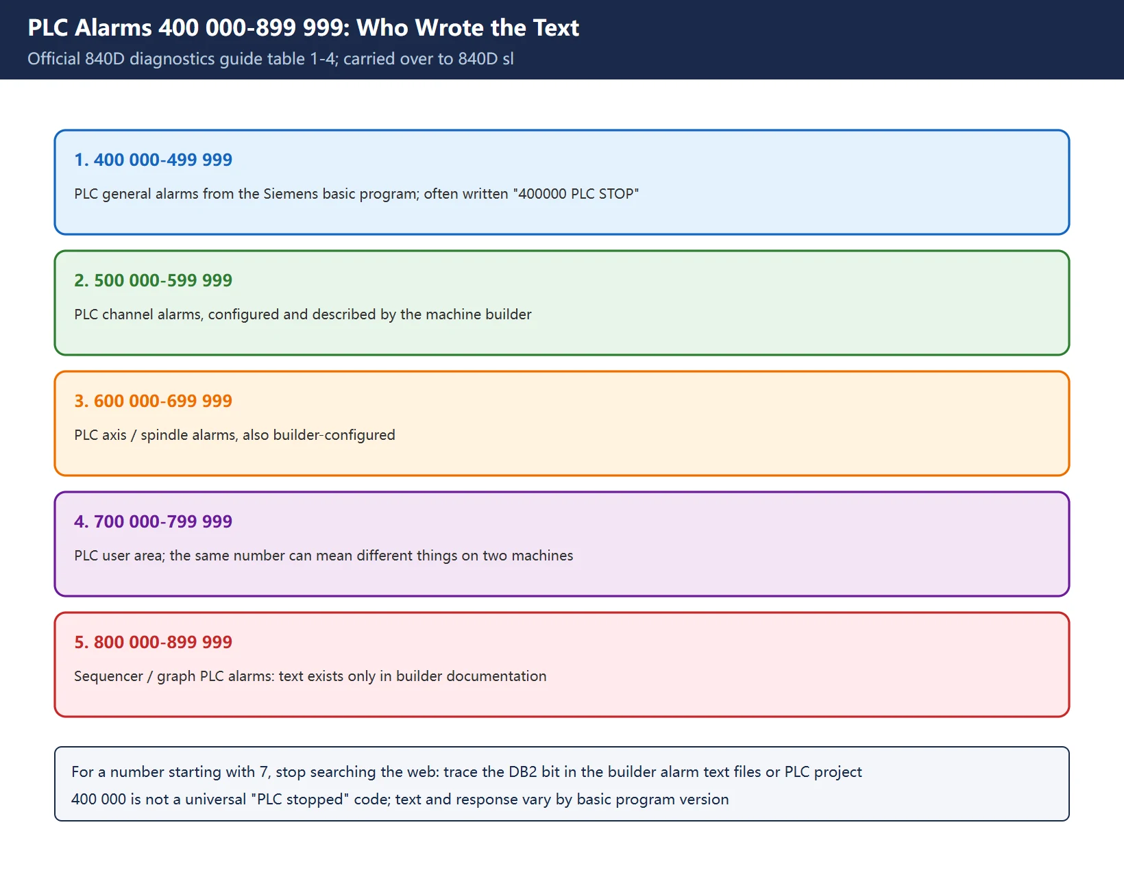
Table 1-4 of the official 840D diagnostics guide (carried over to 840D sl; check your version for subdivisions):
| Range | Official category | Text source |
|---|---|---|
400 000 - 499 999 | General alarms | Siemens basic program |
500 000 - 599 999 | Channel alarms | Configured by the machine builder |
600 000 - 699 999 | Axis / spindle alarms | Configured by the machine builder |
700 000 - 799 999 | User area | Configured by the machine builder |
800 000 - 899 999 | Sequencers / graphs | Configured by the machine builder |
The manual’s footnote is explicit: PLC alarms in 500 000 - 899 999 are configured and described by the machine manufacturer. A number like 700123 can therefore mean entirely different things on two machines from two builders, and Siemens publishes no text for it.
🚨 Correction 2: do not search the web for “840D 700123 meaning”. Look in the builder’s alarm text files or the PLC project. Our 840D PLC user alarm 700xxx location guide shows how to trace the triggering DB2 bit back. To understand the mechanism from the source, read the PLC basic program (MsgUser on FB1, called from OB100) in the machine’s own project — but that is design work; for field triage, trace the bit first.
On
400000 PLC STOP: it is simply one number in the400 000 - 499 999general alarm block. Its text, response and cancel criterion change with the PLC basic program version and builder configuration. It is not a universal “PLC stopped” code. Read the full message next to it and the cancel criterion first.
Table 5 PLC ranges and who owns the text
6. Response levels and cancel criteria: does this need a power cycle?
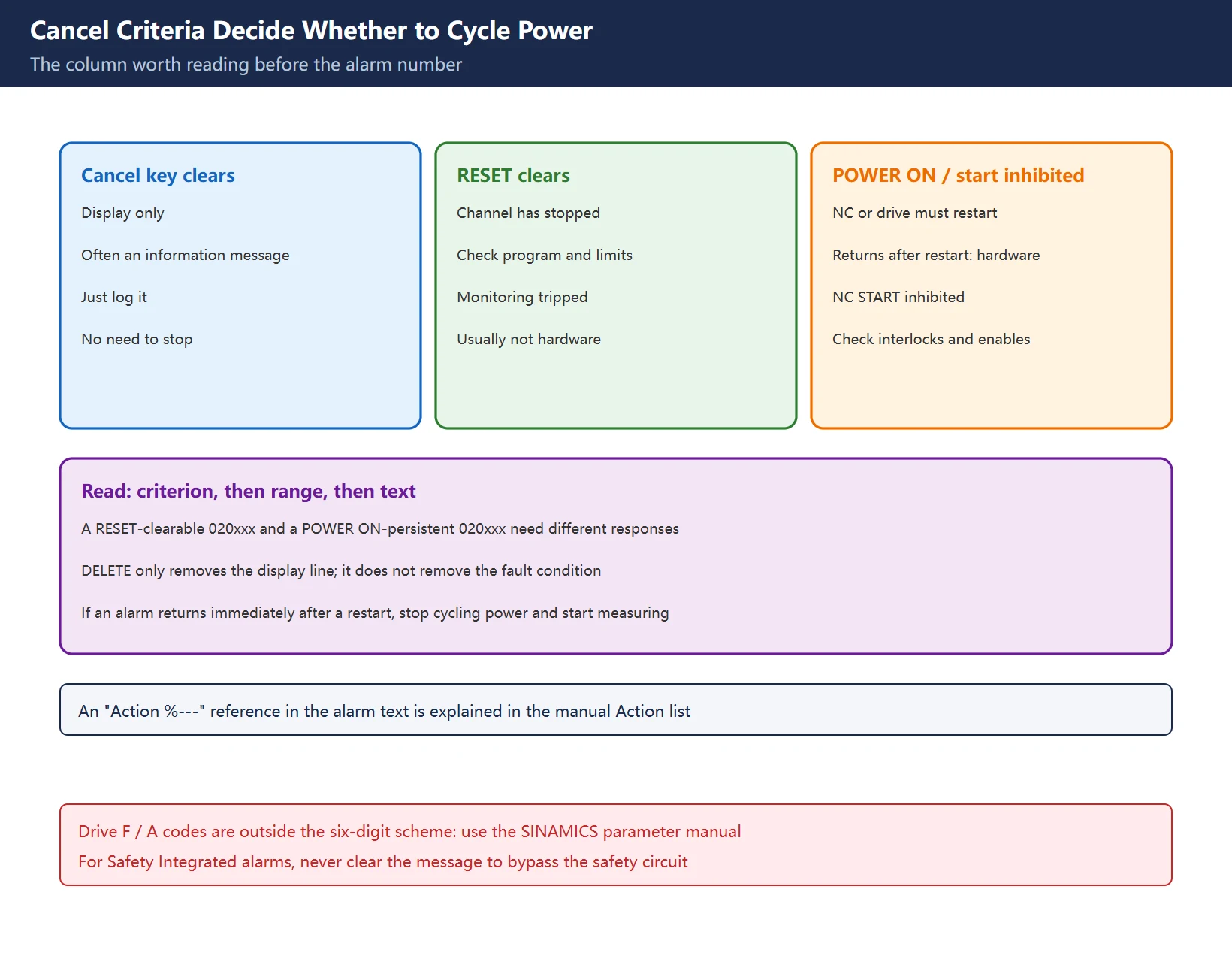
More important than the number is the cancel criterion, because it defines the stop scope and the cost of the next action:
| Cancel criterion | System response | Field action |
|---|---|---|
| Cancel / acknowledge key clears it | Display only, often an information message | Log it, no need to stop production |
| RESET clears it | Channel has stopped | Check program, limits, monitoring functions |
| POWER ON required | NC or drive must restart | Suspect hardware; if it returns immediately after restart, treat as hardware |
| NC START inhibited with no clear route | Something upstream has not released | Check PLC interlocks, enable chain and safety circuit |
Read in this order: cancel criterion → range owner → alarm text. A “RESET clears” 020xxx and a “POWER ON, still returns” 020xxx do not warrant the same response. If an alarm comes straight back after a restart, stop cycling power and start measuring.
⚠️ The DELETE key only removes the current display line; it does not remove the fault condition. RESET clears channel state, but it is not a substitute for a deliberate safety reset. For Safety Integrated alarms, follow the dual-channel and safety-integrated differences rather than clearing the message to get moving.
Table 6 Cancel criteria and response strength
7. Manual chapter index and related pages
- Range overview: diagnostics manual, section “2.3 Alarm number ranges” — start here, tables 2-1 NCK / 2-2 HMI / 2-3 SINAMICS.
- Per-number alarm lists: grouped by range, each entry gives text, cause, response and cancel criterion; locate by six-digit number.
- Action list: explains the “Action %—” references printed in alarm texts.
- PLC alarms: the PLC alarm chapter plus the builder’s alarm text files; anything from
500 000upward must come back to builder documentation. - Drive F / A codes: SINAMICS parameter manual or STARTER / TIA help — not the six-digit range tables.
Elsewhere on this site: start with the alarm number format identification card to identify the control, then use the 828D alarm overview and 828D range breakdown only as cross-system comparison — do not mix the lists. Cycle alarm specifics are in 61000 / 62000 explained. This page covers structure and lookup method only: no manual text is reproduced and no third-party drive or pirated PDF links are provided. Get the manual from the official Siemens support site for your actual software version.
Table 7 Five steps for looking up one number
| Step | Action | Output |
|---|---|---|
| 1. Count digits | Pad with leading zeros to six | A standard number |
| 2. Find the range | Compare with tables 2-1 / 2-2 / 2-3 / PLC table | Owner and manual chapter |
| 3. Read the cancel criterion | Cancel / RESET / POWER ON / start inhibited | Stop scope |
| 4. Read list by time | Oldest entry first in Diagnosis | Root cause, not the last consequence |
| 5. Identify text owner | Siemens / drive / builder | Who to ask for documentation |
Frequently Asked Questions
How do I look up a SINUMERIK 840D sl alarm code?
Pad the shop shorthand to six digits, then identify the range: 000 000-099 999 NCK, 100 000-199 999 HMI, separate mapping ranges for drives, 400 000-899 999 PLC. Next read the cancel criterion on screen and open the alarm list from the oldest entry. Use the official diagnostics manual for your machine’s software version for the per-number text.
What does 840D sl alarm 400000 mean?
400 000 sits in the official PLC general alarm range 400 000-499 999; it is not a machine-data alarm. It is often written “400000 PLC STOP”, but the exact text, system response and cancel criterion depend on the PLC basic program version and builder configuration, so there is no universal meaning. Read the full on-screen message and cancel criterion, then consult the PLC alarm chapter; anything from 500 000 upward needs the builder’s alarm texts.
Which manual chapter covers a given 840D sl alarm code?
Follow the range: NCK numbers use the NCK alarm list, HMI numbers the HMI list, SINAMICS mapping numbers the SINAMICS list, and PLC numbers the PLC chapter. The range overview is in section “2.3 Alarm number ranges”. An “Action %—” reference in the text is explained in the Action list. F / A codes shown on the drive are outside the six-digit scheme and belong in the SINAMICS parameter manual.
Last updated: 2026-11-09
Where to go next
- FANUC Troubleshooting — the full guide library: alarms, diagnosis numbers, servo, spindle, PMC and electrical faults, organised by symptom.
- CNC Repair Tools — which instrument measures what: multimeters, clamp meters, insulation testers and oscilloscopes, with the specification that actually matters.
- Remote Technical Support — have the readings reviewed with you: alarm reverse lookup, PMC ladder analysis and servo tuning advice by call. Repair companies and integrators welcome.
Read the guide, get the right instrument, or walk the diagnosis through with someone — pick whichever you need.
The original Chinese version — same procedure, with the full field notes.

















暂无评论内容