


Sources: the item-to-diagnostic-number mapping on the servo setting screen comes from the GE Fanuc Alpha Series AC Servo Motor Parameter Manual and the FANUC 0i-D Maintenance Guide (both agree: alarm details 1–5 = DGN 200–204, position error = DGN 300, actual current shown in % and A). 🚨 Bit definitions for 3111/3192, the axis-selection parameters of the monitor screen, and spindle diagnostics 403/410/411 differ between series and between Chinese reference articles. Every conflict is flagged below; check the parameter manual shipped with your machine before changing anything.
30-second triage
| What you see | Read this first | Where to look |
|---|---|---|
| High load even in dry run | Actual current (%) per axis | Mechanical drag: lubrication, guideways, ballscrew, brake not released |
| Peaks above 90% while cutting | How many samples the peak lasts | Cutting data, tool wear, inertia ratio mismatch |
| Only one axis is high | Whether DGN 300 rises with it | That axis's mechanics or loop gain, not the whole system |
| Load looks fine but SV0430 / SV0436 is up | DGN 200–204 alarm detail bits | Overcurrent / overload sub-type |
| Want the load meter on the program screen | 3192#7 (PLD) | Not 3111#7 |
| No load meter at all | 3111#0 (SVS), 3111#5 (OPM) | Two different display switches |
Table 0 First checkpoint for six symptoms
1. Three screens: where the load meter lives
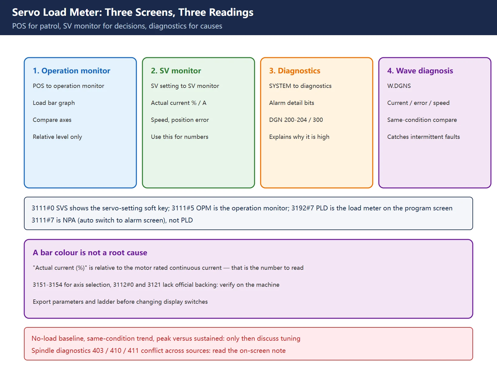
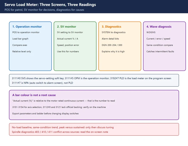
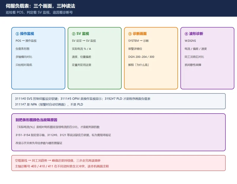
The word “load” means something slightly different on each screen, which is exactly why readings get mixed up:
- POS → [▷] → Monitor / MONI: bar-graph servo and spindle load meters. Good for a daily walk-by and for comparing axes side by side; the bar changes colour above 100%.
- SYSTEM → [▷] → [SV setting] → [SV monitor]: the most complete screen, with
actual current (%),actual current (A),actual speed (rpm)andposition error. The actual-current percentage is the number you can actually judge. If the soft key is missing, the 0i-D Maintenance Guide says set3111#0 SVS = 1and power-cycle. - SYSTEM → DGN]: raw diagnostic numbers (alarm detail bits, position error, temperature), not percentages, but they explain *why* the load is high. See the site’s [diagnostic number reference for the grouped lookup.
Rule of thumb: patrol on POS, decide on SV monitor, find the cause on DGN. Judging “should we replace the amplifier” from the POS bar graph alone is how good drives get scrapped.
Table 1 Three entries, what they show, when to use them
| Entry | Typical path | Reading | Best for |
|---|---|---|---|
| Operation monitor | POS → [▷] → [MONI] | Servo / spindle load bars | Daily patrol, cross-axis comparison |
| SV monitor | SYSTEM → [▷] → [SV setting] → [SV monitor] | Actual current % / A, speed, position error | Quantitative decision, evidence |
| Diagnostic screen | SYSTEM → [DGN] | Bit states and raw values | Root cause, post-alarm review |
| Wave diagnosis | SYSTEM → [▷] → [W.DGNS] | Current / error / speed over time | Intermittent faults, entry shock |
2. Four display switches and two bit-number mistakes
This is the section where copying a blog post does real damage. The following agrees with both the FANUC 0i-D Maintenance Guide and widely used Chinese parameter summaries:
| Bit | Name | Function |
|---|---|---|
3111#0 | SVS | Shows the servo setting / servo tuning soft key; power-cycle after setting to 1 |
3111#5 | OPM | Enables the operation monitor display (monitors axis load torque, etc.) |
3111#6 | OPS | Speed meter content on the operation monitor: 0 = spindle motor speed, 1 = spindle speed |
3192#7 | PLD | Shows the servo load meter and spindle speed meter on the left half of a 10.4-inch position screen |
🚨 Correction 1: 3111#7 is NPA (whether the display auto-switches to ALARM/MESSAGE when an alarm or operator message arrives), not PLD. Setting it to “turn on the load meter” only stops alarm text from appearing. The load-meter display switch is 3192#7.
🚨 Correction 2: Chinese training articles often claim 3151–3154 select which axes appear on the load meter, 3112#0 SGD enables wave diagnosis, and 3121 switches between thermal simulation and spindle load. None of these could be confirmed in the official parameter manual or the 0i-D Maintenance Guide checked for this article, and series differences are undocumented here. They are not presented as copy-and-paste settings. Instead: search by function name (“load meter” / “monitor”) in the parameter support screen, trust the on-screen label of your own control, and back up parameters and ladder before editing anything.
Table 2 Four verified switches vs three unverified claims
| Class | Item | Treatment here |
|---|---|---|
| Verified | 3111#0 SVS / 3111#5 OPM / 3111#6 OPS / 3192#7 PLD | Listed above; trust on-screen labels |
| Corrected | “3111#7 = PLD” | Wrong: NPA and PLD are different parameters |
| Not copied | 3151–3154, 3112#0 SGD, 3121 | Marked as needs on-site verification, no settings given |
3. Reading the percentage: load bands and peaks
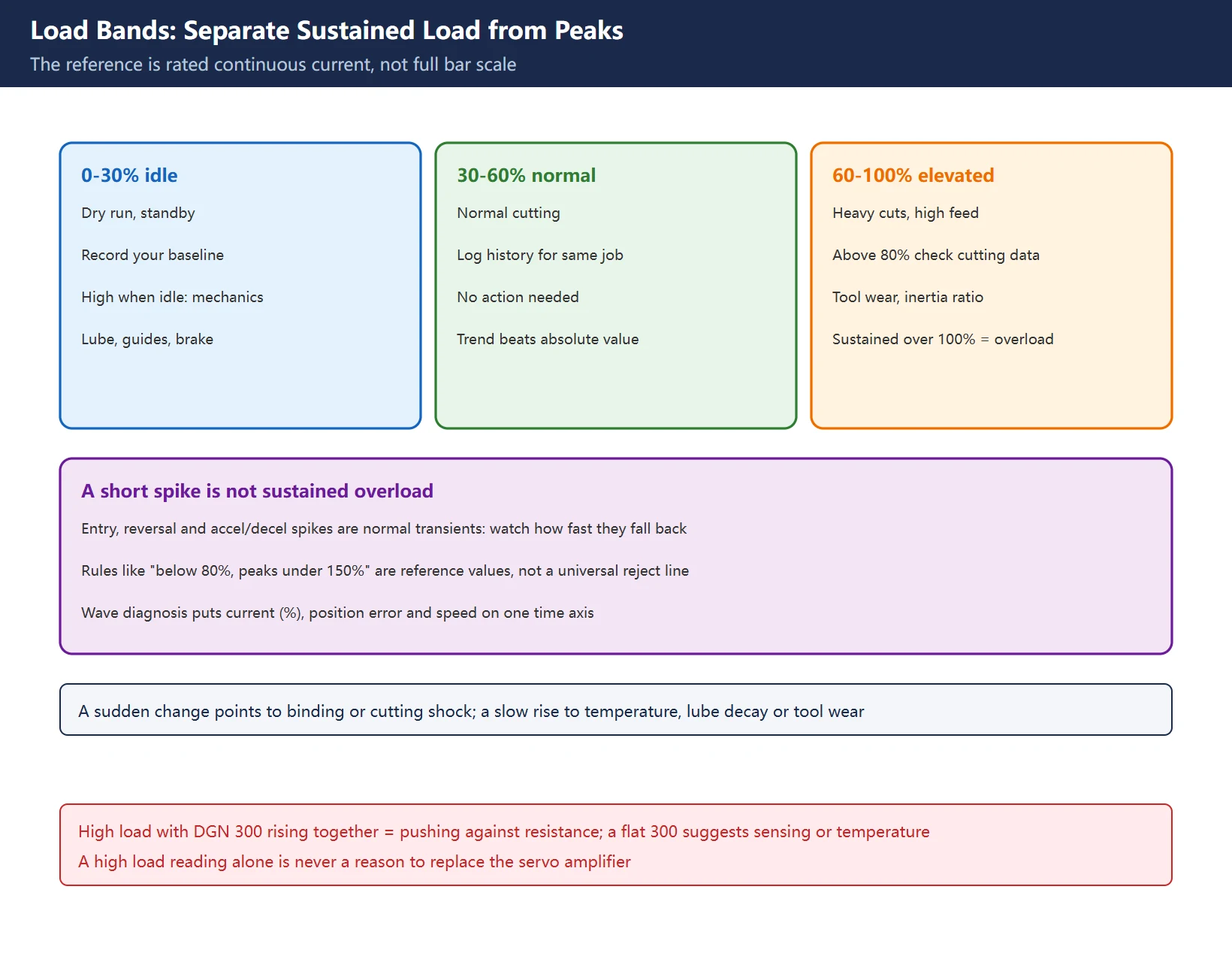
The 0i-D Maintenance Guide defines “actual current (%)” on the SV monitor as a percentage of the motor’s rated continuous current. Common Chinese shop-floor guidance puts normal cutting below 80%, short peaks below 150%, and sustained values above 100% in overload territory.
⚠️ These numbers use different baselines: bar-graph full scale, rated continuous current and short-time peak rating are not the same reference. What follows is therefore a reading method, not a scrapping threshold:
| Band | Typical condition | Action |
|---|---|---|
| 0–30% | Idle, dry run | Record the baseline; if idle is already high, check drag and lubrication |
| 30–60% | Normal cutting | Normal; keep a same-program baseline for later comparison |
| 60–80% | Heavy cutting, high feed | Watch the trend against historical values |
| 80–100% | Near continuous rating | Check cutting data, tool wear, inertia ratio, gain |
| >100% sustained | Overload | Triage now; do not hide it by raising gain |
Table 3 Load bands against your own rated-current baseline
Peaks vs sustained values: a spike at entry, reversal or acceleration is a normal transient; what matters is how fast it falls back. A slowly rising baseline points to temperature, degrading lubrication or gradual tool wear. That is what wave diagnosis is for — record current (%), position error and speed on one time axis. A step change suggests mechanical binding or cutting shock; a slow drift suggests heat, lubrication or wear.
4. Cross-checking with diagnostic numbers 200–204 and 300
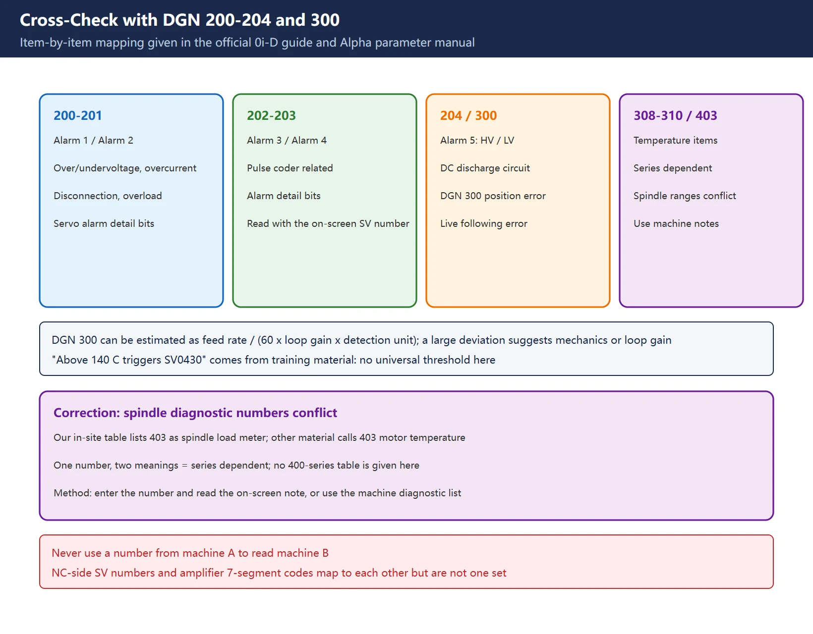
Both the GE Fanuc Alpha parameter manual and the 0i-D Maintenance Guide map SV monitor items to diagnostic numbers. This part is officially verifiable:
| Screen item | DGN | Use |
|---|---|---|
| Alarm 1 | 200 | Servo alarm details (overvoltage / undervoltage / overcurrent / abnormal current bits) |
| Alarm 2 | 201 | Disconnection and overload details |
| Alarm 3 / 4 | 202 / 203 | Pulsecoder-related alarm details |
| Alarm 5 | 204 | High/low DC link voltage, discharge circuit fault details |
| Position error | 300 | Real-time following error per axis |
300 is the column most people skip. If load is high and DGN 300 rises with it, the axis is physically pushing against resistance. If load is high but 300 stays flat, suspect current sensing, winding temperature or a display-baseline issue. Per the manual, position error can be estimated as feedrate / (60 × loop gain × detection unit); a large deviation from that estimate points at mechanics or loop gain first.
Temperature diagnostics 308 (servo motor), 309 (pulsecoder) and 310 (amplifier inverter), plus the widely quoted “140 °C triggers SV0430”, come from Chinese repair and training material and vary by series → labelled “follow the on-screen description of your control”, not stated as universal.
🚨 Correction 3: spindle diagnostic numbers contradict each other. The site’s diagnostic number reference lists 403 as “1st spindle load meter (%)” and 410 as “1st spindle alarm code”, while a widely circulated Chinese article calls 403 “spindle motor temperature” and 410 “1st spindle load meter”. One number, two meanings: this is series-dependent, not a universal table. No 400-series comparison table is given here. Instead, read the label shown on your own diagnostic screen, or use the diagnostic list in the manual shipped with the machine. Never read machine B with machine A’s numbering.
Table 4 Verifiable diagnostics and ranges with conflicts
| Confidence | DGN | Treatment |
|---|---|---|
| Official manuals | 200–204, 300 | Listed with reading actions |
| Series-dependent | 308–310 temperature | Purpose given, no universal threshold |
| Conflicting | 403 / 410 / 411 spindle range | No table; trust the on-screen label |
5. Five causes of a high load reading
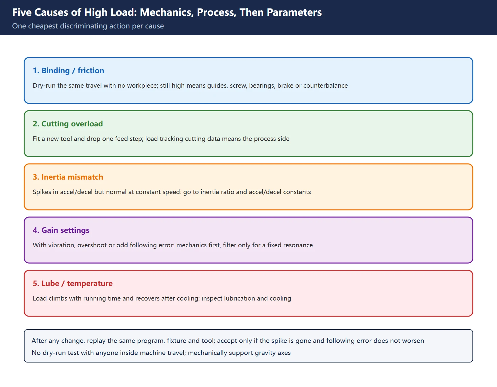
Do not start by raising gain. Work through mechanics, then process, then parameters; each cause has one cheap discriminating test:
- Mechanical binding / drag: run the same path without a workpiece. High load in dry run points to guideways, ballscrew, bearings, a brake that has not fully released, or counterbalance pressure; check whether DGN 300 rises with it.
- Cutting overload: repeat with a fresh tool and one step lower feed. If load scales with cutting data, it is process-side.
- Inertia ratio mismatch: spikes during acceleration only, normal at constant speed. That is the tuning layer — see inertia ratio and accel/decel time constants.
- Poor gain: accompanied by vibration, overshoot or abnormal following error. See gain adjustment and servo vibration; only a fixed-frequency resonance justifies notch filtering.
- Poor lubrication / heat build-up: load drifts upward with running time and recovers after cooling. Check lubrication and the centralised lubrication alarm chain.
Table 5 Five causes × cheapest test × related article
| Cause | Cheapest test | Points to |
|---|---|---|
| Mechanical binding | Same path in dry run | Mechanical chain, brake, counterbalance |
| Cutting overload | New tool / lower feed | Process data |
| Inertia mismatch | Look at accel/decel spikes | /1558.html, /3017.html |
| Poor gain | Vibration plus DGN 300 | /1307.html, /1313.html |
| Lubrication / heat | Cold vs hot comparison | Lube system, cooling |
6. Wave diagnosis and “swap the drive or retune?”
Wave diagnosis (W.DGNS) is not for taking screenshots. It is for same-condition comparison: record the failing part program with current (%), position error and speed aligned, change exactly one thing, then re-record with the same program, fixture and tool. The acceptance test is “the spike disappears and following error does not get worse”, not “the trace looks nicer”.
As for swapping hardware: a high load reading by itself is not a reason to replace a servo amplifier. Hard evidence on the amplifier side is the code the drive reports itself (see the NC-side SV code family in the SV alarm table) plus the overcurrent / undervoltage bits in DGN 200–204. If an overcurrent alarm such as SV0436 OVC appears, use the alarm detail bits to separate the motor-and-cable side from the amplifier side before deciding between an insulation test and a drive replacement. Blaming a large load-meter number and ordering a drive is the most expensive shortcut in this trade.
Safety: recording a trace needs no parameter change. The moment you edit gain, accel/decel or display switches, export parameters and ladder first and log one change at a time. Never run a dry-run test with anyone inside the machine envelope; support gravity axes mechanically.
7. How this relates to the tuning articles on this site
The site already has three tuning-layer articles (how to set gain, how to compute inertia, how to stop vibration). This one is the reading layer (what the number means). Different layers, but each is an entry point to the other:
- Sustained 80–100% → gain adjustment / servo vibration and overshoot
- High only during accel/decel → inertia ratio / 1620/1622 accel-decel
- Overcurrent alarm with normal load → diagnostic number reference and the amplifier code table
- Need to keep the reasoning as evidence → parameter and ladder export
Table 6 Reading layer → tuning layer routing
| Reading-layer symptom | Tuning-layer article | Relationship |
|---|---|---|
| Sustained 80–100% | /1307.html | Rule out mechanics before gain |
| Accel/decel spikes | /1558.html, /3017.html | Inertia and time constants |
| With vibration | /1313.html, /3151.html | Mechanics before filtering |
| Reading disagrees with alarm | /1342.html | Move to diagnostics and drive codes |
Frequently Asked Questions
Where is the Fanuc servo load meter?
Three places: POS → [▷] → [MONI] for the bar-graph patrol view; SYSTEM → [▷] → [SV setting] → [SV monitor] for the quantitative “actual current (%)”; and SYSTEM → [DGN] for root-cause diagnostics. If the SV setting soft key is missing, the 0i-D Maintenance Guide says to set 3111#0 SVS = 1 and power-cycle.
What is a normal Fanuc servo load percentage?
There is no universal pass/fail line across machine models. What is verifiable is that “actual current (%)” is a percentage of rated continuous current; common shop-floor guidance puts normal cutting below 80%, short peaks below 150%, and sustained values above 100% in overload. Compare an idle baseline and a same-condition trend rather than applying one fixed number. Always separate peaks from sustained values.
Does a high load reading mean the servo amplifier must be replaced?
Usually not. Use the dry-run test, a fresh-tool test and DGN 300 cross-check from section 5 to separate mechanics, process and tuning first. Hard evidence against the drive is its own reported code plus the overcurrent / undervoltage bits in DGN 200–204 — not the load percentage. Only after drive-side fault is confirmed (persistent overcurrent bits, same fault with a known-good motor and healthy insulation) does a replacement make sense.
Last updated: 2026-11-09
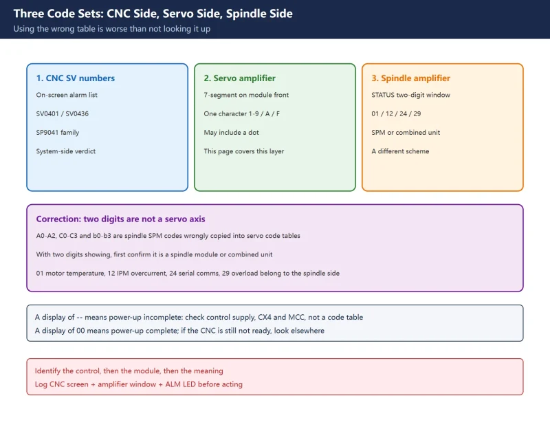
Load normal but overcurrent alarm: read the amplifier 7-segment code
Where to go next
- FANUC Troubleshooting — the full guide library: alarms, diagnosis numbers, servo, spindle, PMC and electrical faults, organised by symptom.
- CNC Repair Tools — which instrument measures what: multimeters, clamp meters, insulation testers and oscilloscopes, with the specification that actually matters.
- Remote Technical Support — have the readings reviewed with you: alarm reverse lookup, PMC ladder analysis and servo tuning advice by call. Repair companies and integrators welcome.
Read the guide, get the right instrument, or walk the diagnosis through with someone — pick whichever you need.
The original Chinese version — same procedure, with the full field notes.



















暂无评论内容