


Sources: the tables below are compiled from FANUC alpha / alpha i servo amplifier service information and publicly published code lists, covering
A06B-6089/6090(alpha SVU),A06B-6079/6080/6096/6097(alpha SVM) andA06B-6114/6117/6124/6127(alpha i SVM). 🚨 The same character means different things on different series. Read the A06B part number on the module nameplate first and use the machine’s own service manual as the final authority. No manual text is reproduced here.
30-second triage
Table 0 Display character and first move
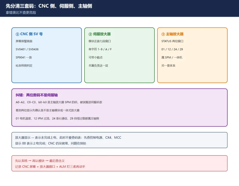
1. Three separate code sets — do not pick the wrong table
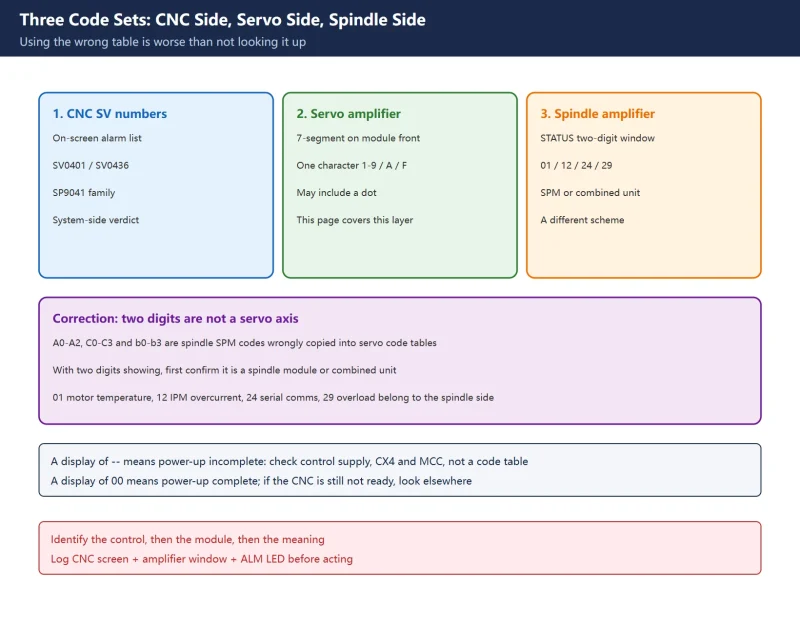
🚨 Correction 1: lists that put A0-A2 (program ROM), C0-C3 (spindle switching) and b0-b3 (amplifier-to-module comms) into a “servo amplifier two-digit code” table have copied the spindle amplifier SPM codes. A servo amplifier has a single-character display; if you are looking at two digits, check whether it is a spindle module or a combined unit. Spindle-side 01 (motor temperature), 12 (IPM main-circuit overcurrent), 24 (CNC-to-SVPM serial comms) and 29 (continuous overload) belong to a different scheme — see /1882.
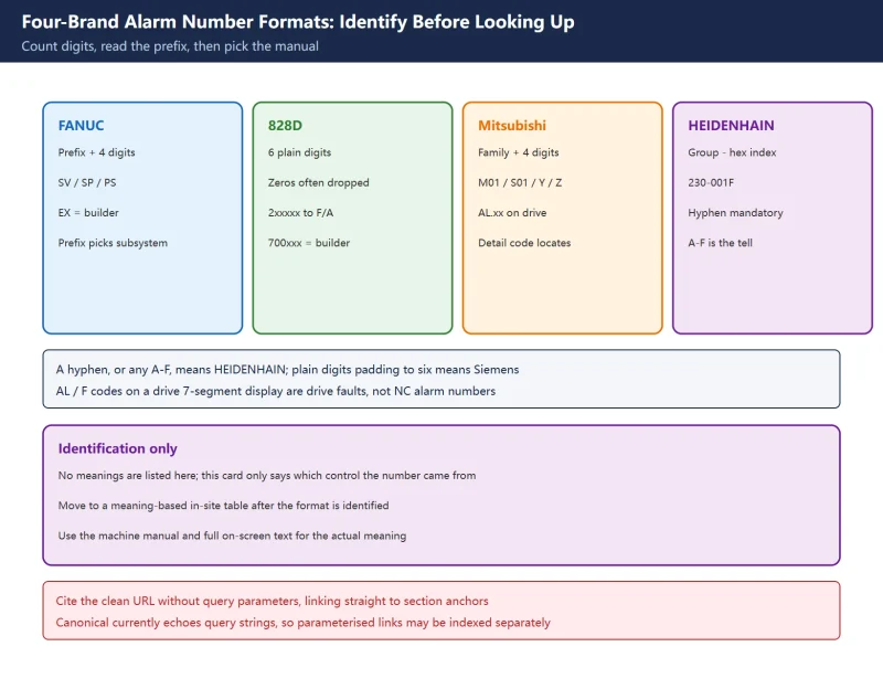
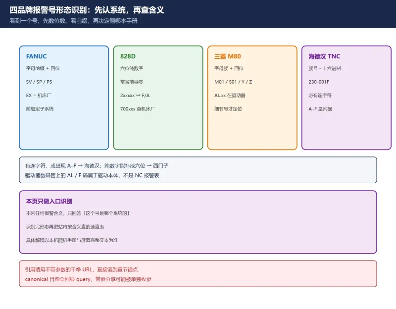
For the layer above this, see our CNC alarm number format identification card: identify the control, then the module, then the meaning.
Table 1 Shapes and screens of the three code sets
2. Where the display is, and whether -- is an alarm at all
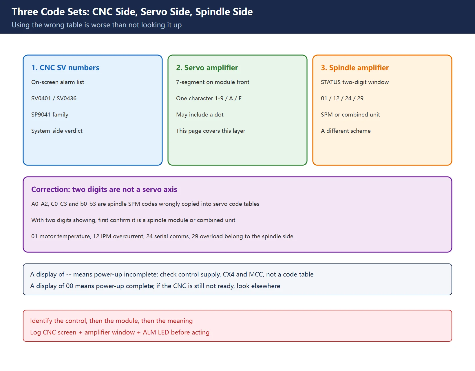
- Location: front of the servo amplifier module, in the STATUS / 7-segment window. On combined units the servo side and spindle side have two separate windows (single character versus two digits).
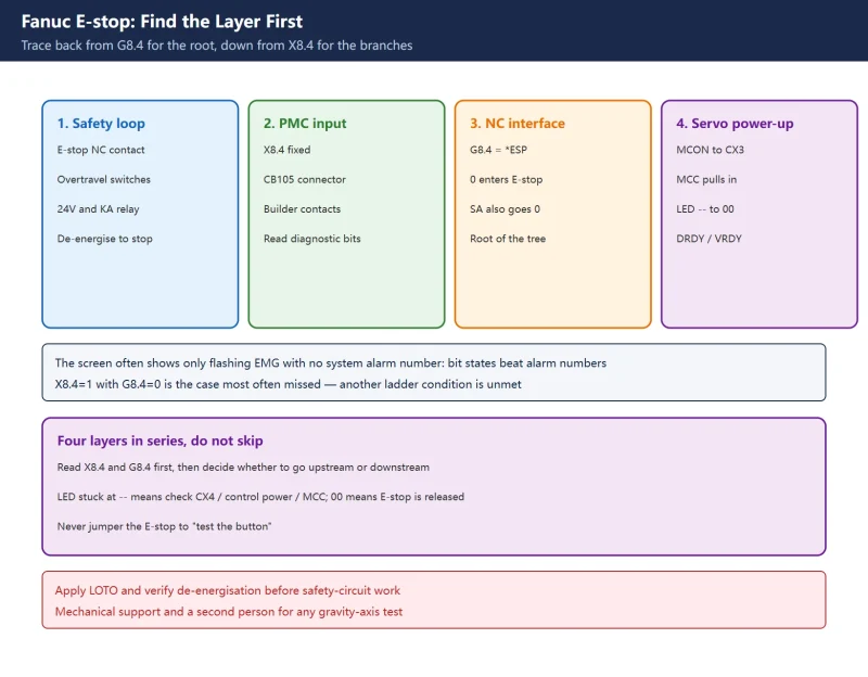
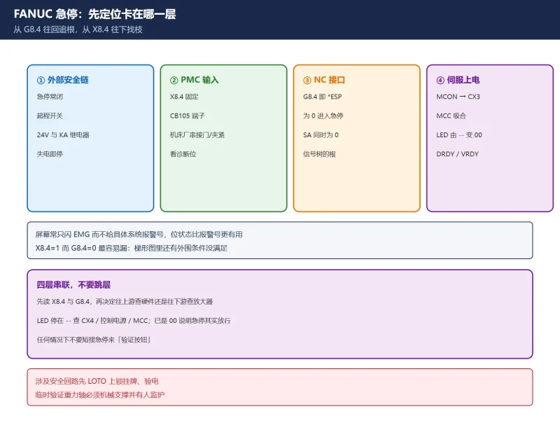
--: the amplifier has not completed power-up or control power is missing. Do not open an alarm code table. Check control supply, the CX4 E-stop chain, MCC and the main circuit; follow the four-layer E-stop chain for this part.00: servo power-up complete, no amplifier alarm. If the screen still shows EMG or “not ready”, look elsewhere.- One steady character: the alarm code for this series. The same character with a dot is a different code, not a flickering display.
- Red ALM LED: read it together with the character, not on its own.
⚠️ With only dashes showing, the CNC message screen often carries extra information. Conversely, an SV alarm on the CNC with 00 on the amplifier is common with FSSB communication or parameter issues. Always log three things before acting: CNC screen + amplifier window + ALM LED.
Table 2 Display states and reading order
| Display | State | Next step |
|---|---|---|
-- | Not powered up | Control supply / CX4 / MCC, no code table |
00 | Power-up complete | Move to CNC side and ready chain |
| Single character | Amplifier alarm | Use the table for this module series |
| Character with dot | IPM-class alarm | Use the decision route in section 5 |
3. alpha SVU (A06B-6089 / 6090): voltage and regeneration dominate
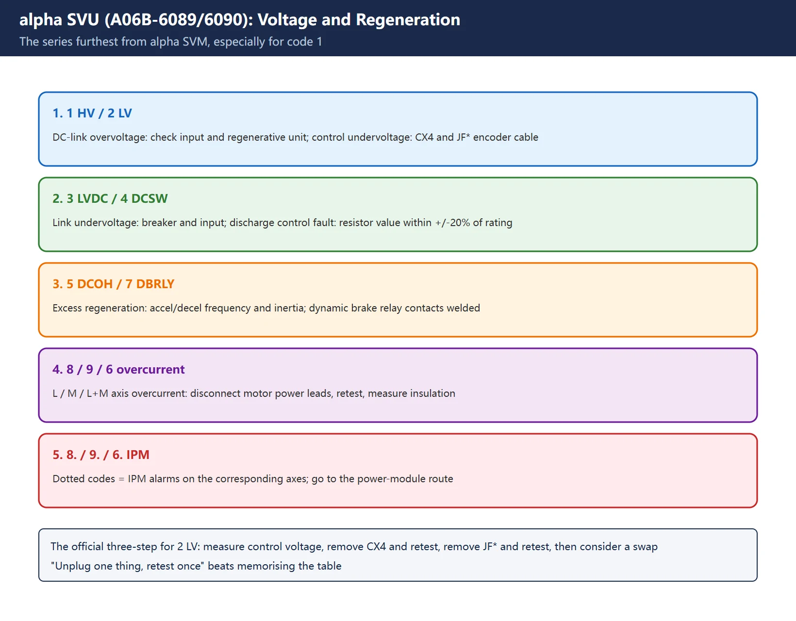
This self-powered alpha SVU series differs most from the SVM tables (especially for 1):
| Code | Name | Meaning | Check first |
|---|---|---|---|
1 | HV | DC link voltage abnormally high | Three-phase input, regenerative unit wiring and resistor |
2 | LV | Control supply undervoltage | Single-phase control voltage, CX4 E-stop input, encoder JF* short |
3 | LVDC | DC link undervoltage / breaker tripped | Breaker, three-phase input voltage |
4 | DCSW | Regenerative discharge control circuit fault | Regenerative resistor wiring and value (within +/-20% of rating) |
5 | DCOH | Excessive regeneration / transformer overheat | Accel/decel frequency, load inertia, regenerative unit |
7 | DBRLY | Dynamic brake relay contacts welded | Dynamic brake circuit |
8 / 9 / 6 | HCL / HCM / HCM | L / M / L+M axis overcurrent | Disconnect motor power leads, retest, measure insulation |
8. / 9. / 6. | IPML / IPMM / IPMLM | IPM alarm on the corresponding axis | See section 5 |
The service information gives a textbook three-step for 2 LV: measure the control voltage → remove CX4 and see whether the alarm disappears (if so, check external E-stop wiring) → on type B interfaces remove JF* and retest (if it clears, check the encoder cable) → only if none of these apply consider replacing the amplifier. This “unplug one thing, retest once” sequence is more useful than memorising the table.
Table 3 Common alpha SVU codes and first checks
4. alpha SVM / alpha i SVM: the same 1 now means a fan
alpha SVM (A06B-6079/6080/6096/6097) and alpha i SVM (A06B-6114/6117/6124/6127) are close, but not identical:
| Code | alpha SVM | alpha i SVM | Note |
|---|---|---|---|
1 | Inverter internal cooling fan stopped | Inverter internal cooling fan stopped | ⚠️ Entirely different from alpha SVU 1 = HV overvoltage |
2 | Control supply undervoltage | Control supply undervoltage | Same as SVU |
5 | DC link undervoltage | DC link undervoltage | Same as SVU |
6 | Overheat (some sources) | Inverter overheat | Different from SVU 6 = L+M overcurrent |
8 / 9 / A | L / M / N axis DC link current alarm | L / M / N axis DC link current alarm | Overcurrent class |
8. / 9. / A. | IPM alarm on that axis | IPM alarm on that axis (including OH) | Expanded in section 5 |
b / c / d | Control command failure (wording varies) | Abnormal inverter motor current | Strong series dependency |
F | Radiator cooling fan stopped | Radiator cooling fan stopped | Separate from internal fan 1 |
P | Amplifier-to-module communication error | Amplifier-to-module communication error | Check module connection |
U / L | FSSB COP10B / COP10A comms error | FSSB COP10B comms error | Optics and slots |
🚨 Correction 2: code 1 is the dividing line. Applying the SVM “fan stopped” reading to an alpha SVU sends you to dismantle a fan while missing a real DC-link overvoltage; applying HV to an alpha i unit sends you to measure three-phase input while a seized fan goes unnoticed. Read the nameplate part number before reading the code — that is the single most important sentence on this page.
⚠️ The table above is a summary of common codes, not a complete manual list. b/c/d are described as “control command failure” in some sources and “IPM (OH) / motor current abnormal” in others; that is series-dependent and we give no universal remedy for them.
Table 4 alpha SVM versus alpha i SVM common codes
5. Dotted codes 8. 9. A.: the IPM decision
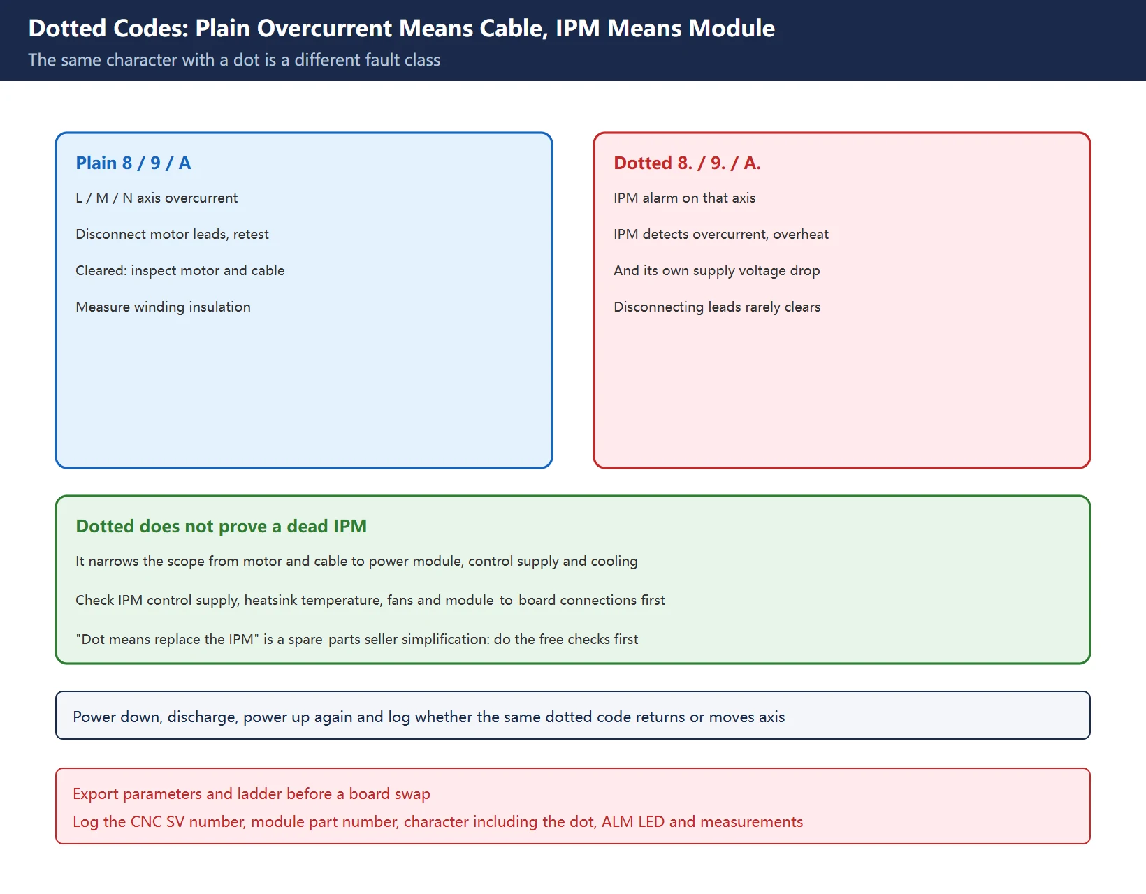
This is the core of the page: the same character with a decimal point is a different class of fault.
| Plain code | Meaning | Dotted code | Meaning |
|---|---|---|---|
8 | L-axis overcurrent (HCL / DC link current) | 8. | L-axis IPM alarm (IPML) |
9 | M-axis overcurrent (HCM) | 9. | M-axis IPM alarm (IPMM) |
A | N-axis overcurrent | A. | N-axis IPM alarm |
6 | alpha SVU L+M axis overcurrent | 6. | alpha SVU L+M axis IPM alarm |
The FANUC service note on IPM alarms is the key: the IPM detects overcurrent, overheat, and a drop in its own control supply voltage. A dotted code therefore does not prove “the IPM is dead” — it narrows the scope from “motor and cable side” to “power module plus its control supply and cooling”.
Decision sequence:
- Reproduce: power down, discharge, power up again, and record whether the same dotted code returns or moves to another axis.
- Plain-code route: disconnect that axis’s motor power leads and power up. Alarm gone → inspect motor windings, phase-to-phase insulation, power cable and connectors; still present → measure insulation, then move to the amplifier side.
- Dotted-code route: disconnecting the motor usually does not clear an IPM alarm. Per the manual, check IPM control supply, heatsink temperature and fans, and module-to-board connections before discussing a power module or board swap.
- Document: log the simultaneous SV number on the CNC, amplifier part number, the display character (including the dot), ALM LED and all measurements. At handover this is worth more than a conclusion.
⚠️ The slogan “dot means replace the IPM” is a spare-parts seller’s simplification. At minimum, rule out control supply and cooling first — both are free, while a board swap costs money and may not fix anything.
Table 5 Plain versus dotted: where the routes split
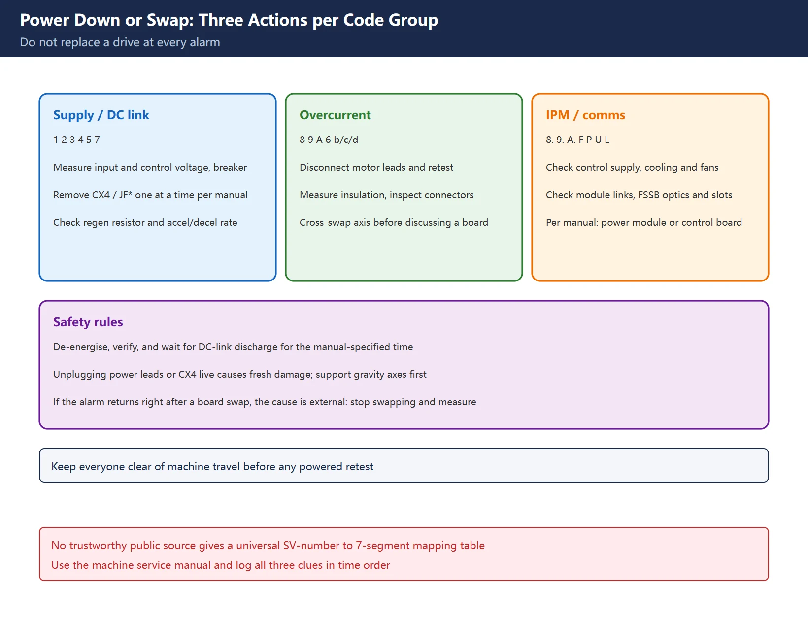
6. Power down or swap the board: three actions per code group
Grouping the codes into three sets, each with three fixed actions, avoids the reflex of swapping a drive at every alarm:
| Group | Contains | Action 1 | Action 2 | Action 3 |
|---|---|---|---|---|
| Supply / DC link | 1 2 3 4 5 7 | Measure input and control voltages, breaker state | Per manual, remove CX4 / JF* one at a time and retest | Check regenerative resistor value and accel/decel frequency |
| Overcurrent | 8 9 A 6 b/c/d | Disconnect motor power leads and retest | Measure winding insulation and phase resistance, inspect cable | Cross-swap axis / module to verify before discussing a board |
| IPM / comms | 8. 9. A. F P U L | Check control supply, cooling and fans | Check module connections, FSSB optics and slots | Per manual, decide power module or control board |
Safety rules: disconnect and verify de-energisation before touching the amplifier, and wait for the DC-link capacitors to discharge for the manual-specified time. Unplugging power leads or CX4 while live causes fresh damage. Support any gravity axis mechanically before work, and never enable an axis with leads disconnected. Before changing parameters or swapping a board, export parameters and ladder as evidence. Nobody may be inside the machine travel during a powered retest.
If the alarm returns immediately after a board swap, the cause is almost certainly external (motor, cable, supply, regenerative unit or FSSB) — stop replacing parts and go back to measuring. For the field sequence around a drive replacement, see servo amplifier replacement.
Table 6 Three code groups and three actions each
7. Mapping to NC-side SV numbers and spindle two-digit codes
One fault usually leaves three clues. Use them to cross-locate, not to substitute for one another:
- CNC screen:
SV0401(servo not ready),SV0436(overcurrent) and similar numbers give the system-side verdict and the time order; see the NC-side SV number table. - Servo amplifier window: a single character says which class of hardware-side cause (supply, overcurrent, IPM, comms). That is this page’s layer.
- Spindle / combined amplifier: two digits, covered by the spindle amplifier code table; do not use it to explain a servo axis.
⚠️ No trustworthy public source gives a universal line-by-line mapping between SV numbers and seven-segment characters — it varies with series, firmware and builder configuration. Tables circulating online are mostly assembled by spare-parts vendors. We therefore do not invent a mapping table, only the method: use the alarm list in the machine’s own service manual, record all three clues in time order, and see which appeared first. Use the alarm number format identification card to decide which manual to open.
Table 7 What each of the three clues answers
| Clue | Answers | Does not answer |
|---|---|---|
| CNC SV number | How the control judged it, alarm order | Which power device failed |
| Servo single character | Supply / overcurrent / IPM / comms class | Exact alarm text and clearing condition |
| Spindle two digits | Spindle module state | Servo axis faults |
Frequently Asked Questions
What does a number on a Fanuc servo amplifier display mean?
It depends on the module part number. On A06B-6089/6090 (alpha SVU), 1 is DC-link HV overvoltage, 3 is LVDC undervoltage and 8/9 are L/M axis overcurrent. On A06B-6114/6117 (alpha i SVM), 1 is the internal cooling fan stopping, 5 is DC-link undervoltage and 8/9/A are per-axis DC-link current alarms. The same character means different things across series: read the nameplate, use that series’ table, and treat the machine’s service manual as final.
What does Fanuc servo amplifier code 8. mean?
A dotted 8. is the L-axis IPM (intelligent power module) alarm, not the plain overcurrent 8. 9. / A. correspond to the M / N axes, and alpha SVU also has 6. for L+M axes. FANUC documentation states the IPM detects overcurrent, overheat and a drop in its control supply voltage, so a dotted code only narrows the scope to the power module, its control supply and cooling — it does not prove the IPM has failed. Check control supply and fan cooling before discussing a module swap.
For a Fanuc servo amplifier alarm, do I swap the board or check the motor cable?
Follow three steps by group. Plain overcurrent (8/9/A/6): disconnect motor power leads and retest → measure winding insulation and phase resistance, inspect the cable and connectors → cross-swap the axis to verify before considering the amplifier. Dotted codes (8./9./A.): disconnecting the leads usually does not clear them; check IPM control supply, cooling and module connections first. Supply / DC-link codes (1/2/3/5): measure input and control voltage and the breaker, then remove CX4 / JF* one at a time per the manual. De-energise, verify and allow DC-link discharge before any work.
Last updated: 2026-11-09
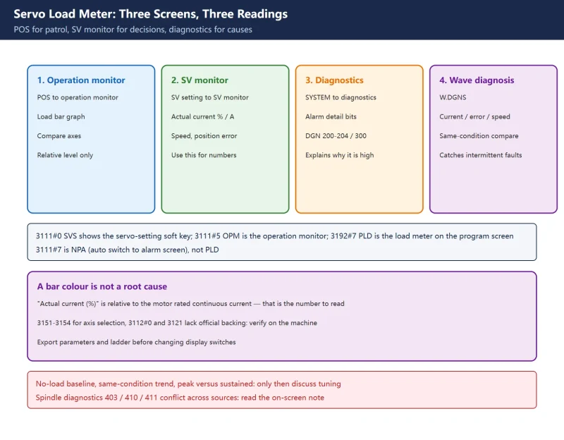
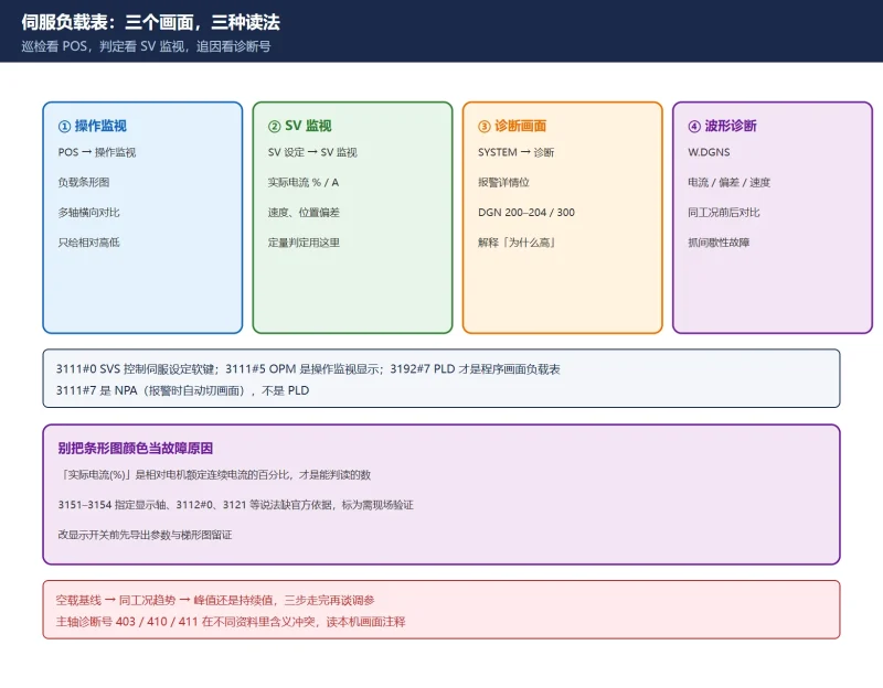
After the hardware side: read the sustained load on the servo load meter
Where to go next
- FANUC Troubleshooting — the full guide library: alarms, diagnosis numbers, servo, spindle, PMC and electrical faults, organised by symptom.
- CNC Repair Tools — which instrument measures what: multimeters, clamp meters, insulation testers and oscilloscopes, with the specification that actually matters.
- Remote Technical Support — have the readings reviewed with you: alarm reverse lookup, PMC ladder analysis and servo tuning advice by call. Repair companies and integrators welcome.
Read the guide, get the right instrument, or walk the diagnosis through with someone — pick whichever you need.
The original Chinese version — same procedure, with the full field notes.
















暂无评论内容