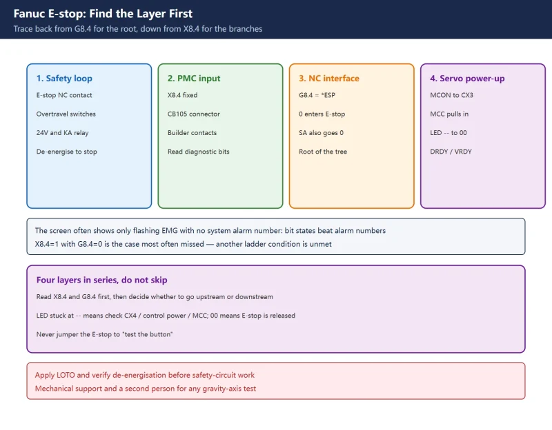



Signal chain and terminal names here follow Chinese technical analyses of the FANUC Series 0i connection manual (emergency stop input X8.4, PMC output G8.4, amplifier CX4 / CX3 / MCON / DRDY). 🚨 X addresses, extra series contacts and relay designations are defined by the machine builder’s ladder, and differ between machines. This article uses the common 0i wiring as a skeleton; always work from the machine’s own electrical drawings and PMC signal list, and take a parameter and ladder export first.
30-second triage
| Symptom | Look first | Criterion |
|---|---|---|
| EMG flashing, no alarm number | PMC diagnostic screen X8.4 / G8.4 | Whichever is 0 first tells you which layer to climb |
X8.4=0, external loop looks fine | 24V safety chain, E-stop / overtravel switches, relay coil | A broken NC contact reads 0; check 24V and the KA relay |
X8.4=1 but G8.4=0 | Extra contacts after X8.4 in the ladder | Door, clamp, pressure, tool-position “branch” signals |
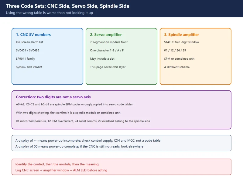
G8.4=1 but MCC will not pull in | Amplifier CX4, CX3, control power, amplifier alarms | Is the LED -- or 00? |
Amplifier LED stuck at -- | E-stop still active / control power / amplifier | It should change from -- to 00 after power-up |
| Reset button has no effect | Whether reset is independent of the E-stop button | Reset must be a deliberate separate action |
Table 0 First landing point for six symptoms
1. Four layers: where is the E-stop stuck
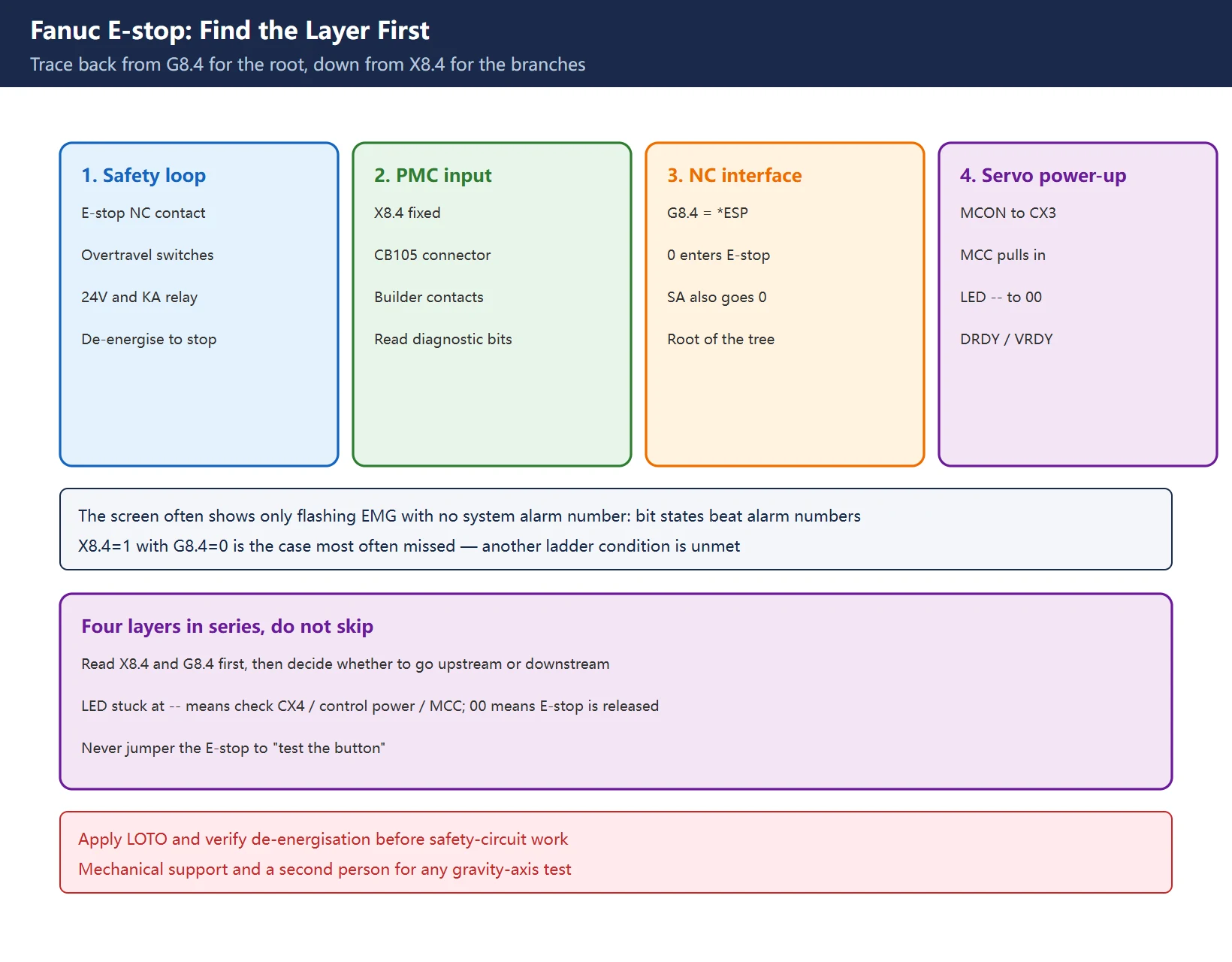
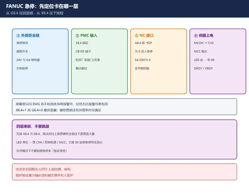
Treat the E-stop as a four-layer series chain, not a button:
- External hardware safety loop: E-stop NC contact, axis overtravel switches, safety relay, 24V supply and the KA interposing relay;
- PMC input and ladder:
X8.4(E-stop input) plus the door, clamp, pressure and tool-position X/R contacts the builder puts in series after it; - NC interface signal:
G8.4, the emergency stop signal*ESPsent from PMC to CNC. When it is 0 the CNC is reset into emergency stop and the servo ready signal SA becomes 0; - Servo power-up chain: CNC axis card issues MCON → amplifier CX3 internal contact → main contactor MCC → amplifier returns DRDY / VRDY → servo ready.
Rule of thumb: trace back from
G8.4to find the root, then down fromX8.4to find the branches. A Chinese technical analysis puts it well:G8.4is the “root” of the E-stop signal tree and the other X and R signals are “branches”. If you only stare at the button and the overtravel switches, you will stall on any machine where the builder added extra ladder conditions.
Scope note: the in-site articles on safety relay component selection and reading machine electrical drawings cover components and schematics, while Mitsubishi M80 emergency stop is a different brand; this article is specifically the FANUC side, branched by X-bit state.
Table 1 Four layers, typical signals and where to look
2. The electrical chain: button, safety relay, 24V, X input
The typical connection recommended in the FANUC connection manual: the E-stop switch and all axis overtravel switches are wired in series with a 24V relay coil; one contact of that relay goes to the emergency stop input of the CNC control unit, another to the CX4 connector (pins 2 and 3) of the amplifier power module. Pressing E-stop or opening any overtravel switch de-energises the coil, its normally-open contacts open, the CNC reports emergency stop, the MCC coil drops out and the main circuit opens.
On the 0i family, the emergency stop input to the PMC is fixed at address X8.4, brought in through the CB105 connector of the I/O unit and normally driven by the NC contact of the E-stop button. Typical field wiring: the external safety loop energises interposing relay KA; one KA NO contact goes to CB105 so that X8.4="1" in normal state; another KA NO contact goes to amplifier CX4 pins 2 and 3.
🚨 Why a broken wire also triggers E-stop: a signal name prefixed with
*is negative logic (active low), so 0 means E-stop is active. The loop is therefore designed as “normally closed, de-energise to stop”, and any broken wire, poor contact or loss of 24V has exactly the same effect as pressing the button. That is not a defect — it is deliberate fail-safe design.
Table 2 Two destinations, four terminals
| Destination | Terminal / address | Purpose |
|---|---|---|
| I/O unit → PMC | CB105 → X8.4 | Tells the PMC the external safety loop state |
| Amplifier power module | CX4 (pins 2, 3) | Directly removes amplifier main-power enable |
| Amplifier internal contact | CX3 | Energises the MCC coil (typically 110V) |
| Main contactor | MCC / KM | Closes main contacts to power the amplifier |
Rewiring an E-stop circuit is safety-circuit work: apply LOTO (lockout/tagout), use qualified personnel, and repeat the functional test afterwards (section 7). For component selection and safety relay categories see safety relay component selection.
3. PMC side: *ESP negative logic, G8.4 and diagnostics
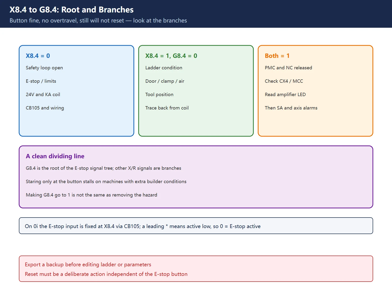
When X8.4 is 0, the PMC ladder passes the external E-stop to the CNC so that G8.4 becomes 0; the CNC is reset into emergency stop and SA (servo ready) becomes 0. The important part is the step in between: the ladder is usually not “X8.4 equals G8.4”.
A widely cited Chinese technical analysis gives the typical example: the ladder has an Xn.m (for instance a tool-magazine door switch, common on imported machines) in series after X8.4. In that case even with a perfectly healthy external loop and X8.4="1", if Xn.m="0" then G8.4 stays 0 and the machine remains in E-stop. That is the most common explanation for “the button is fine, no overtravel, but it just will not reset”.
Table 3 Reading the X8.4 / G8.4 / SA combinations
X8.4 | G8.4 | Meaning | Next step |
|---|---|---|---|
| 0 | 0 | External safety loop open | Check E-stop / overtravel switches, 24V, KA relay, wiring |
| 1 | 0 | Another ladder condition is not met | Online-monitor every series contact after X8.4 |
| 1 | 1 | PMC and NC have released | Move on to MCC, CX4, amplifier LED and SA |
| Any | Any | EMG flashing, no specific alarm number | Often only a PMC / external alarm such as EX1000 |
Recommended diagnostic order:
- Open the PMC diagnostic screen or the online ladder and read
X8.4first; X8.4=0→ go back to section 2 for the external loop;X8.4=1withG8.4=0→ trace back from the G8.4 coil through every series contact to find the one at 0;- Once the specific X point is found, go to the electrical drawing for that switch, connector and 24V supply;
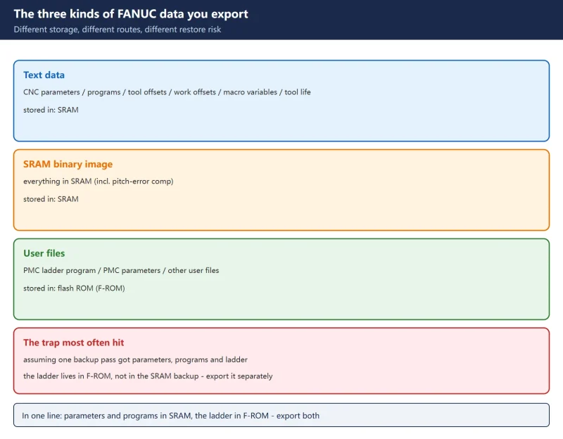
- Before editing any ladder or parameter, take an export backup and follow PWE write enable.
Do not skip step 2 and swap the safety relay or jumper terminals: the builder put door, clamp and pressure into the E-stop chain for a safety reason. Making G8.4 go to 1 is not the same as making the hazard go away.
4. NC to servo: MCC pull-in conditions and the amplifier LED
After the PMC releases the E-stop there is still a servo power-up sequence, and it is often misread as “E-stop not released”:
- The CNC completes its power-on self test and the axis card sends MCON (Main Contactor ON) to the servo amplifier over FSSB;
- Conditions: no emergency stop (via CX4), no other alarm, amplifier control power healthy;
- The amplifier’s internal contact CX3 closes, the MCC coil energises and the main contacts pull in;
- The amplifier status display changes from two dashes
--to00; - The amplifier returns DRDY / VRDY (Drive Ready / Velocity Ready) to the CNC, completing servo power-up.
While the system is in emergency stop (*ESP), this sequence cannot complete and the amplifier display stays at --. That gives a clean dividing line for “released but still not ready”:
- LED still
--→ E-stop chain / CX4 / control power / amplifier hardware; look upstream; - LED already
00with MCC pulled in → E-stop actually released; the problem is an NC-side ready condition, SA, or another builder interlock. Stop dismantling the button.
Table 4 LED state and fault ownership
| Amplifier LED | MCC | Reading |
|---|---|---|
-- | Not pulled in | E-stop active / CX4 open / control power / amplifier fault |
00 | Pulled in | Servo power-up complete, E-stop chain basically released |
| Fault code / alarm | Depends on model | Amplifier's own alarm — check the amplifier manual |
5. E-stop reset troubleshooting table
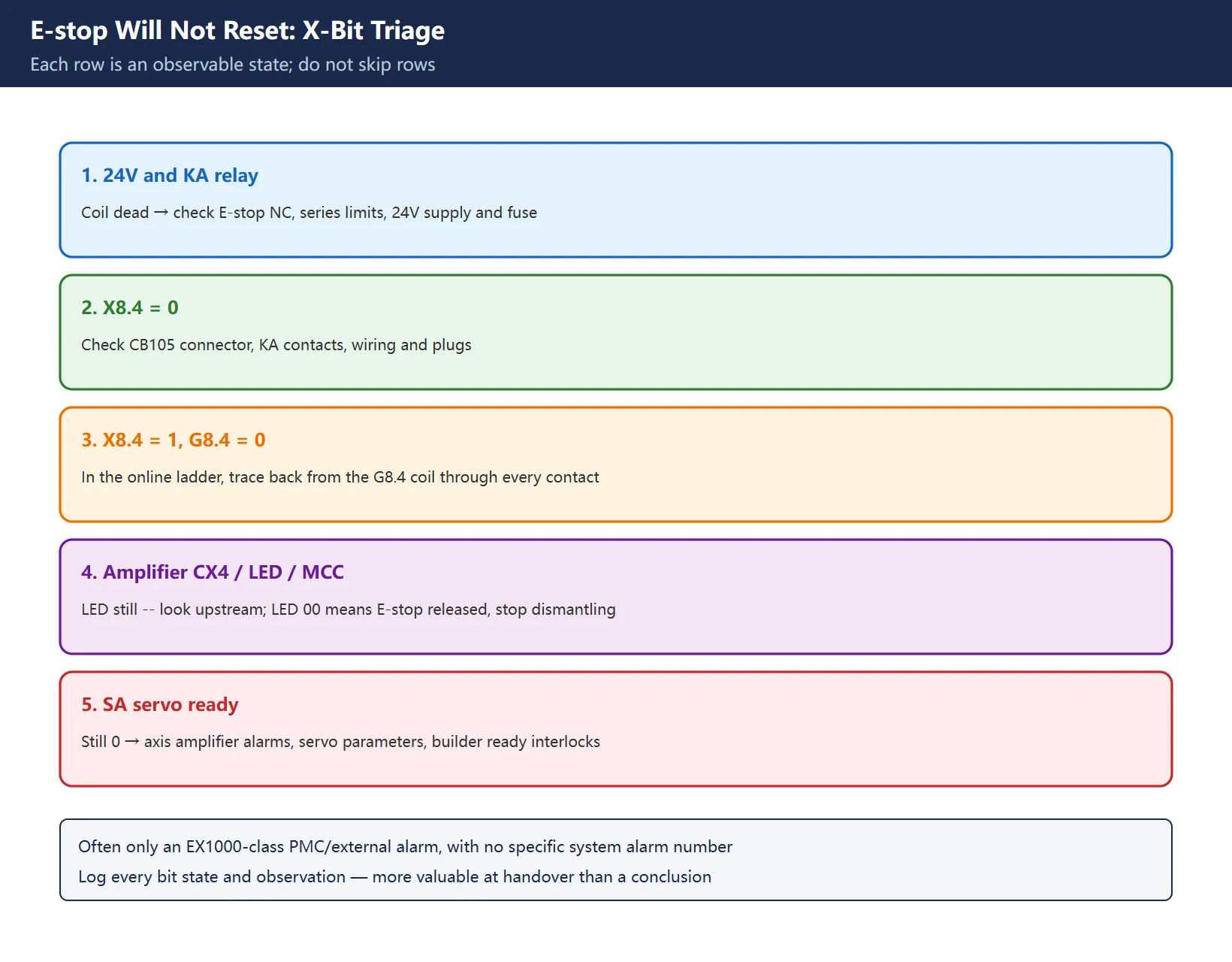
The four layers compressed into a table to execute in order. Every row corresponds to an observable state — do not skip rows:
Table 5 Ordered triage for an E-stop that will not reset
Common mistake: treating the click of the reset button as proof that the safety relay has reset. Reset must be a deliberate action independent of the E-stop button, and you should confirm the relevant PMC flag actually cleared. The MDI [RESET] key alone does not remove the E-stop state from the main circuit.
6. Single-channel legacy machines vs dual-channel and safety integrated
Legacy machines are usually single channel: one NC series loop, one relay; a wire break stops the machine but a fault in the channel itself is hard to detect. Newer machines commonly use dual-channel safety relays with safety-integrated / dual-channel safety inputs: two paths are monitored independently, a mismatch latches and cannot be cleared with an ordinary reset, and dedicated diagnostics apply.
This changes troubleshooting in practical ways:
- On a dual-channel machine, measuring one healthy channel is not enough — check both channels and their timing mismatch;
- Safety-integrated alarms and interlocks have their own diagnostic screens and are upstream conditions; see the in-site safety integrated topic;
- Some newer machines tie E-stop to STO / SS1 safety functions, and whether power is removed after a controlled stop or immediately determines whether a gravity axis drops (closely related to the gravity-axis brake article in this batch; see reading machine electrical drawings for safety-loop notation).
🚨 Never jumper the two safety-relay inputs “just to check whether the button is bad”. Detecting that mismatch is exactly what dual-channel monitoring is for; jumpering deliberately disables the protection.
7. Safety rules and acceptance
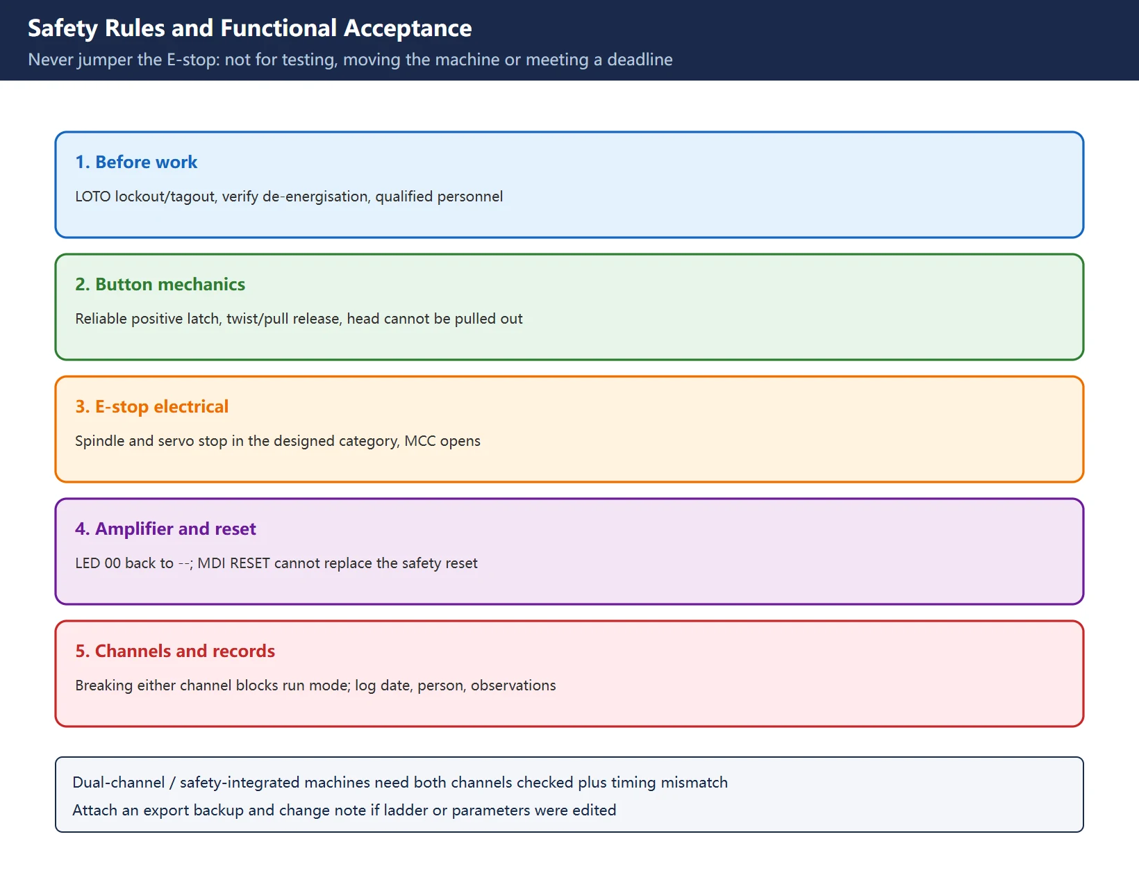
Never jumper the E-stop, whether the reason is testing a button, moving the machine temporarily or meeting a deadline. The E-stop chain is part of personnel protection; with it jumpered the machine can start with no protection at all.
- Any work on the safety circuit starts with LOTO (lockout/tagout), verified de-energisation, and qualified personnel;
- When a gravity axis or mechanism must be moved for a temporary test, provide mechanical support first, have a second person watching, use single block at low feed, and keep a hand near the E-stop;
- After restoration, verify item by item: positive latching and twist-to-release of the button, spindle and servo stopping in the designed stop category on E-stop, MCC actually opening, amplifier returning to
--, reset requiring a deliberate separate action, and the machine refusing to enter run mode with one safety channel disconnected; - Record test date, technician and observed values in the maintenance log;
- If ladder or parameters were changed, attach an export backup and a change note.
Table 6 Acceptance checklist and safety lines
| Item | Pass criterion |
|---|---|
| Button mechanical function | Reliable positive latch, twist/pull release, head cannot be pulled out |
| E-stop electrical function | Spindle and servo stop in the designed category, MCC opens |
| Amplifier state | Returns from 00 to --, no unexpected fault code |
| Reset independence | MDI [RESET] cannot substitute for the safety reset |
| Channel integrity | Breaking either safety channel blocks run mode and alarms |
| Records and handover | Date, personnel, observations, ladder/parameter backup complete |
Frequently Asked Questions
Is *ESP normally closed or normally open, and why does a broken wire trigger E-stop?
*ESP is negative logic (active low) — the leading * in a FANUC signal name means exactly that: a value of 0 means E-stop is active. The loop is therefore built as “normally closed contacts in series, de-energise to stop”, so an open E-stop button, overtravel switch, 24V supply, interposing-relay contact or wire has exactly the same effect as pressing the button. This is deliberate fail-safe design: a broken wire must lead to a safe state rather than “assume nobody pressed it and keep running”. In practice, do not just test the button for continuity — measure the whole 24V series loop, the KA relay coil and both contact sets, and the CB105 and CX4 terminals.
The reset button was pressed but the servo is still not ready. Which signal first?
Read X8.4 and G8.4 on the PMC diagnostic screen or in the online ladder. X8.4=0 means the external safety loop is still open, so check the E-stop / overtravel switches, 24V and the KA relay. X8.4=1 with G8.4=0 is the case most often missed — the builder has put door, clamp, pressure or tool-position conditions in series after X8.4 in the ladder, so trace back from the G8.4 coil through every contact. Only when both are 1 do you move on to the amplifier: an LED stuck at -- means the CX4 / control power / MCC sequence did not finish; an LED already at 00 with MCC pulled in means E-stop really has been released and you should check SA and axis amplifier alarms. The screen often shows only a flashing EMG with no specific system alarm number, so bit states are more useful than alarm numbers here.
Can I jumper the E-stop to check whether the button is faulty?
No, not for any reason. Jumpering the E-stop deliberately disables personnel protection, and the machine can then start with no protection at all; on dual-channel / safety-integrated machines a channel mismatch will latch anyway, so jumpering simply introduces a new fault. The correct method is to isolate power under LOTO and measure continuity across the button’s NC contact with a multimeter, or read the X8.4 bit on the PMC diagnostic screen. If a gravity axis must be moved for a test, provide mechanical support first, have a second person watching, use single block at low feed, and keep a hand near the E-stop. Afterwards repeat the full functional test and record it in the maintenance log.
Last updated: 2026-11-08
Fanuc Gravity-Axis Brake: Release Sequence and Z-Axis Drop
When the amplifier shows –: check the E-stop chain first
Where to go next
- FANUC Troubleshooting — the full guide library: alarms, diagnosis numbers, servo, spindle, PMC and electrical faults, organised by symptom.
- CNC Repair Tools — which instrument measures what: multimeters, clamp meters, insulation testers and oscilloscopes, with the specification that actually matters.
- Remote Technical Support — have the readings reviewed with you: alarm reverse lookup, PMC ladder analysis and servo tuning advice by call. Repair companies and integrators welcome.
Read the guide, get the right instrument, or walk the diagnosis through with someone — pick whichever you need.
The original Chinese version — same procedure, with the full field notes.





















暂无评论内容