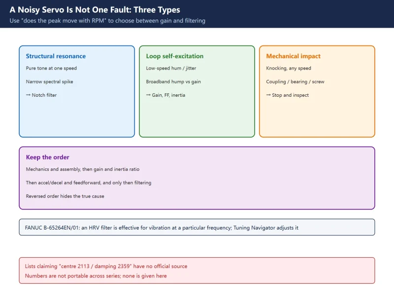



Filter parameters, the sweep tool and the tuning order in this article come from the official FANUC SERVO TUNING PROCEDURE (BASIC) (B-65264EN/01, αis/αi/βis series) and Notice for usage of HRV filter of αi series Spindle software (B-65280EN/05-01); multi-filter allocation also references a machine-tool builder’s technical column on SERVO GUIDE / SERVO GUIDE PLUS. 🚨 Filter parameter numbers are not portable across control series and software versions. Lists circulating online — “centre frequency 2113 / damping 2359 / bandwidth always 20”, or “4048–4051 spindle notch” — have no official source and contradict themselves across pages of the same aggregator. None of them is used here, and no copy-and-paste parameter numbers are given. Use the parameter manual shipped with the machine or the SERVO GUIDE filter screen. Before editing, see FANUC Parameter Write Protect (PWE) and parameter export.
30-second triage
Table 0 First action for six field symptoms
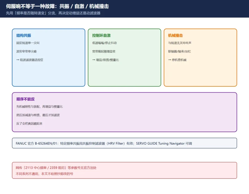
1. Three noise types first
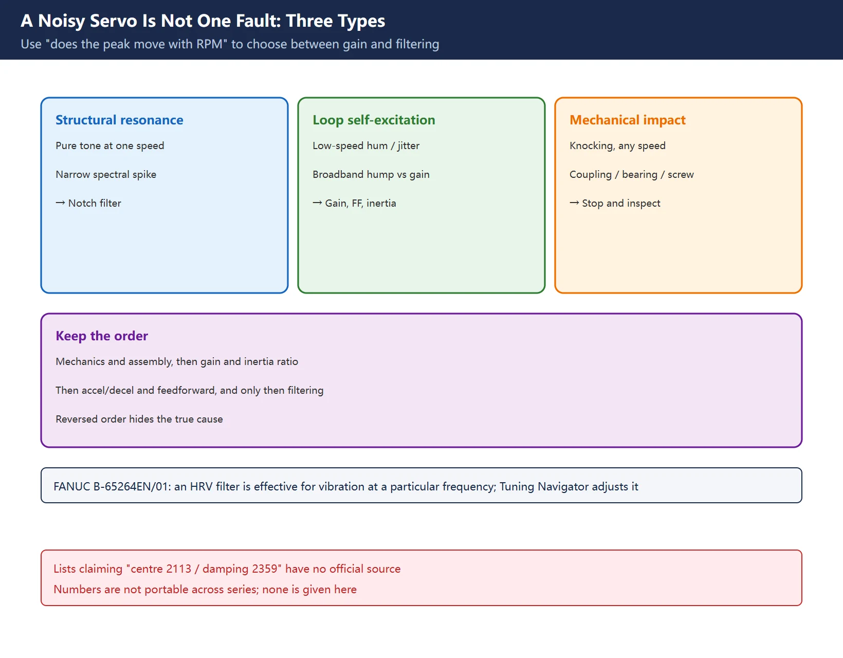
“A noisy servo” is at least three different problems, and the wrong method hides the real fault:
- Structural resonance: a stable single-tone squeal at one speed or one axis position, with a narrow spike in the speed or torque spectrum. This is what a notch filter is for.
- Loop self-excitation / broadband noise: a low-speed hum, jitter at standstill, changing with gain; a broad spectral hump rather than one spike. The fix lies in gain, feedforward, inertia ratio and friction compensation — see servo gain tuning order and inertia ratio identification.
- Mechanical impact: periodic knocking unrelated to speed — loose coupling, damaged bearing, ball-screw nut play, guard interference. A filter only erases the noise from the waveform while the wear continues. Stop the machine and inspect.
The full symptom-classification table is in the in-site servo anomaly triage; this article picks up only after a single-frequency resonance has been confirmed.
A useful test: change the speed and see whether the peak frequency moves with it. A peak that tracks RPM usually relates to rotating parts or cogging; a peak that stays at a fixed Hz is a structural natural frequency and is the right target for a fixed-centre notch filter.
Table 1 Three types, their spectral signature and ownership
| Type | Spectral signature | Changes with RPM | Owned by |
|---|---|---|---|
| Structural resonance | Narrow single spike | Frequency roughly fixed, amplitude varies | Notch filter |
| Loop self-excitation | Broadband hump | Clearly changes with gain / speed | Gain, feedforward, inertia ratio |
| Mechanical impact | Pulse train, messy harmonics | Proportional to rotation frequency | Stop and inspect mechanics |
2. Reading the peak frequency with Servo Guide
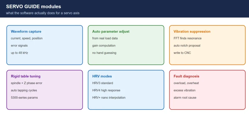
The official FANUC SERVO TUNING PROCEDURE (BASIC) states, in its “Resonance elimination filter adjustment” section, that some machines resonate at a particular frequency and that a resonance elimination filter (HRV Filter) is effective for removing vibration at that frequency; it also states that the Tuning Navigator of SERVO GUIDE is useful to adjust the HRV Filter. The manual’s Filter Tuning screen flow is: estimate the resonance frequency from measured data → calculate recommended filter parameters → review and write them. The screen fields are Control [Hz] (centre frequency), Width [Hz] (bandwidth) and Damping, with example recommendations such as 250 Hz / 50 Hz / 5% and 530 Hz / 100 Hz / 5%, plus four filter slots Fillet1–Fillet4.
A practical sweep sequence:
- Fix the operating condition: record axis, direction, feed rate, spindle speed, load, active gear range and gain group. A filter is tuned for one condition; change the condition and the peak moves.
- Capture waveforms: use SERVO GUIDE to record speed command / speed feedback / torque command; add an accelerometer where supported (newer AI servo tuning offers optional hardware accelerometer support).
- Look in the frequency domain: run frequency analysis on the torque or speed waveform and read the Hz of the spike. This is the basis for everything that follows — do not enter a centre frequency without a measured one.
- Reproduce it: repeat the sweep 2–3 times under identical conditions. Only a stable peak counts as structural resonance; an intermittent one means connectors, looseness or interference first.
- Record a baseline: archive the pre-change waveform, parameter values, following error and a photo of the surface finish. Without them you cannot tell improvement from regression.
Tool version note: machine-builder documentation states that AI gain/filter auto-tuning requires SERVO GUIDE VER 11.90 or later, or SERVO GUIDE PLUS VER 1.0 or later, and is an option. Without that option, a manual sweep plus manual entry of the three parameters still works — never skip frequency measurement just because AI tuning is unavailable.
Table 2 Six condition items to record during a sweep
| Item | Why it must be logged |
|---|---|
| Axis / direction | Resonance often appears in one axis and one direction only |
| Feed rate, spindle speed | Peak amplitude depends on excitation strength |
| Load / fixture / travel position | Natural frequency shifts with position on gantries and vertical axes |
| Active gain group and gear range | A gear change can make the filter ineffective or excessive |
| Peak frequency and amplitude | The only valid basis for the centre frequency |
| Pre-change following error and surface photo | The reference for judging side effects |
3. The three notch parameters and multi-filter allocation
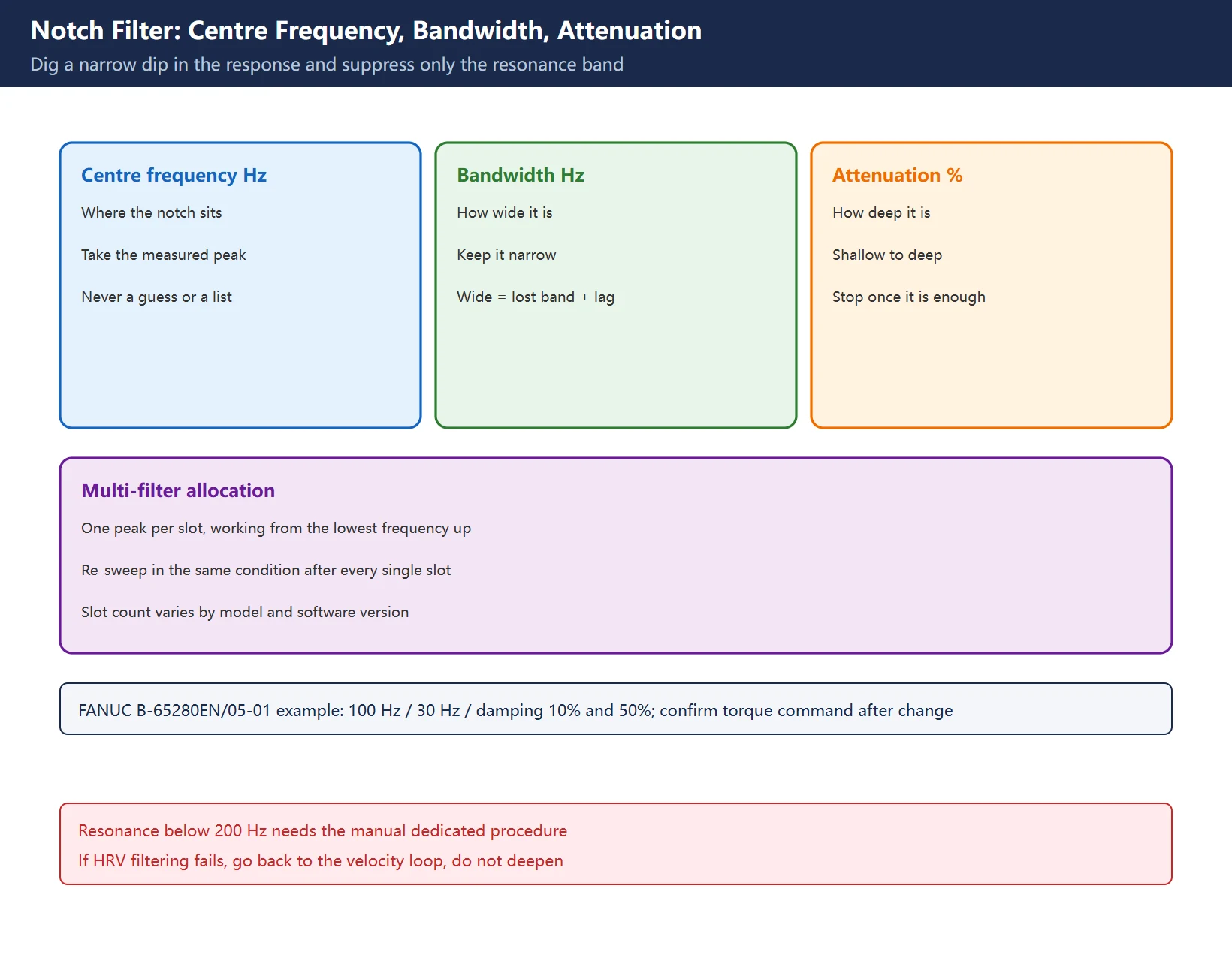
A notch filter digs a narrow dip in the frequency response, suppressing only the resonance band while leaving other frequencies largely untouched. Each parameter has a distinct job:
Table 3 The three parameters, their meaning and setting principle
| Parameter | Unit | Controls | Setting principle |
|---|---|---|---|
| Centre frequency | Hz | Where the notch sits | Take it directly from the measured peak, not from a guess or a forum list |
| Bandwidth | Hz | How wide the notch is | Keep it narrow; a wide notch eats useful neighbouring bandwidth and adds phase lag |
| Attenuation / damping | % | How deep the notch is | Increase from shallow to deep and stop as soon as it is enough; too deep slows the response |
The official Notice for usage of HRV filter of αi series Spindle software (B-65280EN/05-01) gives a useful sense of scale: its examples compare centre frequency 100 Hz, bandwidth 30 Hz, damping 10% and 50%, and explicitly require rotating the spindle after the change to confirm the torque command shows no abnormal oscillation. The notice also states two important limits:
- When the machine resonance frequency is below 200 Hz, follow the dedicated procedure in chapter 3, paragraphs (2) and (3) of the manual rather than the standard routine;
- If the HRV filter cannot eliminate the resonance, use another method — for example a larger time constant of the torque command filter (No.4121 in that notice) or a smaller velocity loop gain (No.4040–4054). Note that these numbers come from a spindle software notice, not from feed-axis parameters — do not copy them onto a servo axis.
Worth emphasising: the filter is not a universal fix. FANUC itself says that when the filter fails, go back and adjust the velocity loop. The online claim that “every resonance needs a notch” simply does not hold.
On multi-filter allocation: the official manual’s Filter Tuning screen shows Fillet1–Fillet4; a machine-builder technical column describing SERVO GUIDE PLUS AI gain/filter tuning lists “suppression filters 1–5 (centre frequency Hz / bandwidth Hz / attenuation %)” with before/after parameter tables. The slot count varies by model and software version — use the screen on the machine. The allocation rule is simple:
- One peak per slot, working from the lowest frequency up; never cram two peaks into one overly wide notch;
- After each slot, return to the same condition and re-sweep to confirm the target peak dropped without lifting others;
- Suppress the highest-amplitude, most damaging peak first; leave the rest alone if they do not affect quality;
- Record all three values for every slot and hand them over with the waveforms.
Table 4 Multi-filter allocation and re-measurement order
| Step | Action | Pass criterion |
|---|---|---|
| 1 | Sweep and list all peaks with amplitude | Peak frequencies stable and reproducible |
| 2 | Largest peak → slot 1, enter the three parameters | Target peak amplitude clearly reduced |
| 3 | Re-sweep in the same condition | Neighbouring band not noticeably cut |
| 4 | Next peak → next slot, repeat 2–3 | Each slot has its own record |
| 5 | Full acceptance after all slots | See section 7 |
4. The tuning order: mechanics, then gain, then filtering
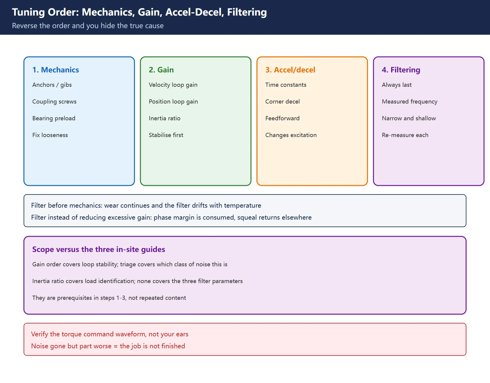
Reverse the order and you hide the true cause. Applying a deep filter first buries problems like a loose coupling, wrong bearing preload or excessive gain; they reappear as soon as load or temperature changes, and by then the waveform has been reshaped by the filter, making diagnosis harder.
Recommended four-layer order (an engineering sequence, not a numbered list from the manual):
- Mechanical stiffness and assembly: anchors, gib adjustment, coupling set screws, bearing preload, screw supports, counterbalance. No filter is more than a painkiller while something is loose.
- Gain and inertia ratio: set velocity loop gain, position loop gain and load inertia ratio into a sound range using the servo gain tuning order and inertia ratio identification; use the anomaly triage for classification.
- Accel-decel and feedforward: time constants, corner deceleration and feedforward change excitation strength and following error — see FANUC accel-decel time constants. The official manual likewise places fine accel/decel, feedforward and position gain after velocity loop gain.
- Only then add the notch filter: if a clear single-frequency resonance peak survives steps 1–3, enter the three parameters from sections 2–3.
Scope note: the in-site gain order covers “how to stabilise the loop”, the anomaly triage covers “which class is this noise”, and inertia ratio covers load identification. None of the three covers the three filter parameters or the sweep procedure; this article only references them as prerequisites.
Table 5 Skipping a step and what it costs
| Shortcut | Consequence |
|---|---|
| Filter before checking mechanics | Wear continues; filter drifts out of tune with temperature and load |
| Add a filter instead of reducing excessive gain | Phase margin is consumed; self-excitation returns at another speed |
| Set maximum attenuation immediately | Slower response, larger following error, worse contour accuracy |
| Fill several slots without re-measuring | Impossible to know which slot worked or how to roll back |
5. Interaction with HRV and high-speed / high-precision functions
The name “HRV filter” is easy to misread. HRV (High Response Vector) is the high-response current/velocity loop control; the HRV Filter is the resonance suppression filter attached to it. The official manual lists “automatic tuning of HRV filters” as one function of the SERVO GUIDE Tuning Navigator, alongside automatic velocity gain tuning and support for high-speed/high-precision settings.
Three interactions matter:
- Raising HRV / velocity loop gain widens the control bandwidth, so a mechanical resonance previously masked by low gain appears — “it started squealing after we sped it up” is typical, not a hardware failure;
- High-speed / smoothing functions reshape the command’s accel-decel profile, which changes the excitation spectrum. After enabling AICC smoothing a shift in peak position or amplitude is normal, so re-sweep with the final combination of active functions;
- Feedforward and fine accel/decel act on following error, while filter-induced phase lag partly cancels their benefit. Judge them together at acceptance; “the noise is gone” alone proves nothing.
That is exactly the point of the official notice’s instruction to rotate the spindle after parameter changes and confirm no abnormal oscillation of the torque command: the verification target is the torque command waveform, not your ears.
Table 6 Function changes that interact with the filter
| What changed | Effect on the filter | Re-sweep needed |
|---|---|---|
| Higher velocity loop / HRV gain | May excite a new resonance peak | Yes |
| AICC, smoothing or feedforward switched | Excitation spectrum and following error change | Yes |
| Fixture, workpiece weight or travel position | Structural natural frequency moves | Yes |
| Repeat production in the same condition | None | Sample check is enough |
6. Side effects of an over-deep filter
A filter is not free. It inserts a phase-lag element into the control loop, with three main costs:
- Slower response: excessive bandwidth or attenuation makes the axis sluggish to commands, with a trailing accel/decel ramp;
- Larger following error and poorer contour accuracy: quadrant protrusions on arcs, corner overcut, worse surface finish on curved paths. The FANUC tuning manual’s feedforward and fine accel/decel exist precisely to compress such errors, and an over-applied filter works directly against them;
- Masking the true cause: mechanical looseness and poor gain tuning stay hidden, then reappear with temperature, load or position changes — harder to locate the second time.
Rule: increase attenuation from shallow to deep, stop as soon as it is enough, and keep bandwidth narrow. The official notice takes the same line: when the HRV filter cannot remove the resonance, do not keep deepening it — go back to the torque command filter time constant and velocity loop gain. If the noise disappears but the part gets worse, back off attenuation first, re-measure following error, and do not compensate by simply lowering gain further.
7. Acceptance: waveform, surface finish and following error
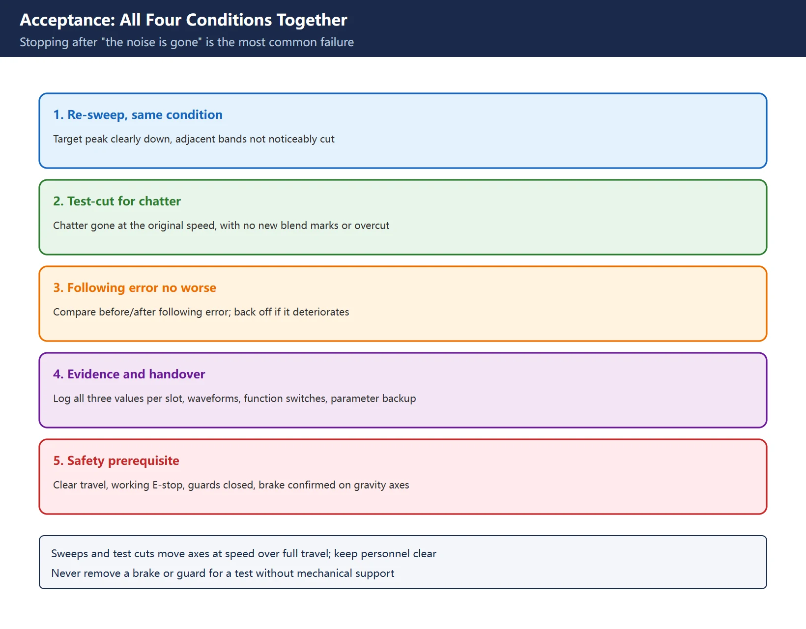
All four conditions must hold together. Stopping after the first one is the most common way this job goes wrong:
- Re-sweep in the same condition: identical axis / direction / speed / load / position as before; the target peak amplitude is clearly reduced and adjacent bands are not noticeably cut;
- Test-cut for chatter marks: machine at the speed and feed that originally caused the problem; chatter is gone or clearly reduced, with no new blend marks or overcut;
- Following error does not get worse: compare pre/post following error and position deviation in SERVO GUIDE; measure contour error on arc or corner parts if needed. If worse, back off attenuation or bandwidth;
- Evidence and handover: record centre frequency / bandwidth / attenuation for every filter slot, before/after waveforms, the active combination of function switches, a parameter backup (parameter and ladder export), and the operating condition this tuning applies to.
🚨 Safety: sweeps and test cuts move axes at speed over full travel. Confirm the travel is clear of interference, the E-stop works, guards are closed and personnel are clear; on vertical or gravity axes confirm brake and counterbalance first. Never remove a brake or guard for a test without mechanical support.
Frequently Asked Questions
Does every servo squeal need a notch filter?
No. Use the triage in section 1 first: only a narrow single-frequency spike is an indication for a notch filter. Broadband hum and standstill jitter are usually gain, feedforward, inertia ratio or friction problems, better addressed through the gain order and inertia ratio identification; periodic metallic knocking means coupling, bearing or ball-screw trouble, where the machine must be stopped and inspected — a filter only erases the noise from the waveform while wear continues. The official FANUC Notice for usage of HRV filter of αi series Spindle software (B-65280EN/05-01) also states that when the HRV filter cannot eliminate resonance, other means should be used, such as a larger torque command filter time constant or a smaller velocity loop gain. In addition, resonance below 200 Hz requires the manual’s dedicated procedure rather than the standard three-parameter routine.
How do I read the centre frequency from a waveform?
Capture speed feedback or torque command with SERVO GUIDE in the exact condition where the noise occurs, run frequency analysis on the waveform (or use the manual’s Filter Tuning / Tuning Navigator, which estimates the resonance frequency from measurement data and computes recommended parameters), and read the Hz value of the spike — that is your centre frequency. Repeat the sweep 2–3 times in the same condition to confirm the peak is stable; a peak whose frequency stays put while only amplitude changes with RPM is a structural natural frequency suitable for a fixed-centre notch. The manual’s Filter Tuning screen shows example recommendations such as 250 Hz / 50 Hz / 5% and 530 Hz / 100 Hz / 5%, but those are examples and must not be copied as machine parameters. With no measured frequency, do not enter a centre frequency — and never take a “common value” from a forum list.
Following error got worse after adding the filter. What now?
The notch is too wide or too deep, and its phase lag has eaten the response. Work in order: back off the attenuation first, then narrow the bandwidth, re-sweeping the waveform and measuring following error after each change. If noise and following error cannot both be satisfied, return to the order in section 4 and re-check mechanical stiffness and gain tuning instead of compensating by lowering gain further. The official notice’s approach is the same: when the HRV filter cannot remove resonance, switch to other means (torque command filter time constant, velocity loop gain) rather than deepening the notch. Acceptance always requires three things together: the target peak is down, test-cut chatter has improved, and following error and contour accuracy have not deteriorated. “The noise is gone” alone is not a completed adjustment.
Last updated: 2026-11-08
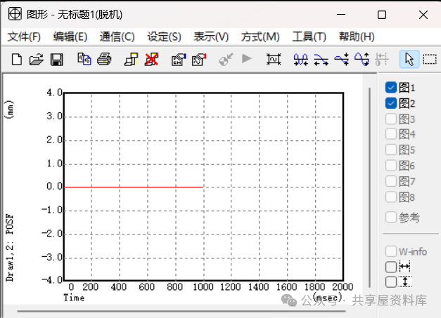
FANUC SERVO GUIDE: Waveform Analysis
Where to go next
- FANUC Troubleshooting — the full guide library: alarms, diagnosis numbers, servo, spindle, PMC and electrical faults, organised by symptom.
- CNC Repair Tools — which instrument measures what: multimeters, clamp meters, insulation testers and oscilloscopes, with the specification that actually matters.
- Remote Technical Support — have the readings reviewed with you: alarm reverse lookup, PMC ladder analysis and servo tuning advice by call. Repair companies and integrators welcome.
Read the guide, get the right instrument, or walk the diagnosis through with someone — pick whichever you need.
The original Chinese version — same procedure, with the full field notes.





















暂无评论内容