



FANUC Matrix Keypad Panel Replacement: Remapping PMC Ladder Logic and Resolving R-Address Conflicts
Field notes by 共享屋 (Gongxiangwu) — a real panel-swap job, compiled from wechat field notes and expanded over time. Part of the 《FANUC PMC 维修学习资料》 workbook.
Swapping a FANUC matrix keypad panel — what we call a “scanned panel”, because the keys are read by a scan routine that writes their states into the R area — looks like a pure hardware job. In practice the hardware is the easy 20%. The real work is porting the PMC ladder logic so that every key on the new panel drives the same machine function as before.
This is a field record of replacing one matrix panel with another. It assumes you already know:
- FANUC PMC ladder-editing software (LADDER-III or FAPT-LADDER) — start with What Is a PMC in Fanuc? Ladder Logic, Addresses and Scan Time and the FANUC PMC Ladder Diagram Beginner Tutorial.
- Basic FANUC I/O hardware connection knowledge (CB connection units, I/O Link).
If you only want the physical teardown, stop here — the value of this article is the address-mapping and ladder-rewrite method.
Table of Contents
- 1. The four-stage workflow
- 2. Stage 1 — Backup and information gathering
- 3. Stage 2 — Map old vs. new key addresses
- 4. Stage 3 — Rewrite the ladder logic
- 5. Stage 4 — Download and verify
- 6. Safety rules (never skip)
- 7. Related reading on CNCShare
- 8. To be updated — notes for later
1. The four-stage workflow
The whole job breaks into four stages:
- Collect information & back up the original PMC program.
- Map the old vs. new panel key addresses, and find every I/O address that collides between the two panels.
- Rewrite the ladder logic step by step until every section is fully modified and replaced.
- Download the new PMC program to the CNC and test / verify.
⚠️ Stage 1 is non-negotiable. Never touch a running ladder without a verified backup. See How to Backup and Restore a Fanuc PMC Program from LADDER-III and the full FANUC data backup & restore guide (ALL I/O / BOOT SRAM).
2. Stage 1 — Backup and information gathering
Before any change:
- Make a complete backup of the original PMC program (and, ideally, a full ALL-I/O backup). Keep the backup file named by date and machine.
- Record the old panel model and, critically, the CB connection-unit model it uses.
In our case the old panel used CB106 and the replacement uses CB107. That single difference changes which I/O points the panel physically occupies — and it is the root of the address conflict you will meet in Stage 3.
3. Stage 2 — Map old vs. new key addresses
Before editing anything, list the key addresses each panel occupies.
| Item | Old panel | New panel |
|---|---|---|
| Connection unit | CB106 | CB107 |
| Key-state storage | R1280 – R1299 (20 bytes / 160 bits) | R addresses that may collide with the existing machine ladder |
| Mapping method | — | one-to-one where a correspondence exists; manual, key-by-key otherwise |
Key facts:
- The original panel’s keys are scanned into R1280 through R1299 — that is 20 bytes (160 bits) of R area.
- The new panel’s scan routine (NEW.LAD) also writes its key states into R addresses. Some of those R addresses overlap with the existing machine ladder → that is the conflict you must resolve.
Practical tip: build a cross-reference table first. For every key on the new panel, write down (a) the old R address that performed the same function and (b) the new R address the scan routine assigns. Where a clear 1:1 correspondence exists you can batch-replace; where there is none you must replace one key at a time, guided by the new panel’s function definition.
You need to be able to read the original PMC logic to do this correctly. If the ladder is undocumented, spend Stage 2 reverse-mapping each old key’s function before touching anything.
4. Stage 3 — Rewrite the ladder logic
This is the core. Two sub-steps:
(1) Neutralise the colliding addresses. Before the new panel is introduced, take every I/O point in the original ladder that uses CB107 (the new panel’s connection unit) and re-route it through an intermediate relay (an unused R/E-area address). Doing this first gives you a clean, conflict-free base to build on, and makes later edits reversible.
(2) Swap the scan routines.
- Delete the old panel scan routine from the ladder.
- Copy the new panel scan routine (NEW.LAD) into the ladder.
- Inside NEW.LAD, the R addresses that collide with the old machine program must already have been redirected to intermediate variables (this redirection was completed as prep work). Verify each one.
Replacement strategy recap:
- Batch replace when the old and new key addresses have a known correspondence.
- Manual, one-by-one replace when they do not — always against the cross-reference table from Stage 2.
Note: this stage requires you to actually understand part of the original PMC program. Blind search-and-replace across a ladder you don’t understand is exactly how panels end up “working except for these three keys”.
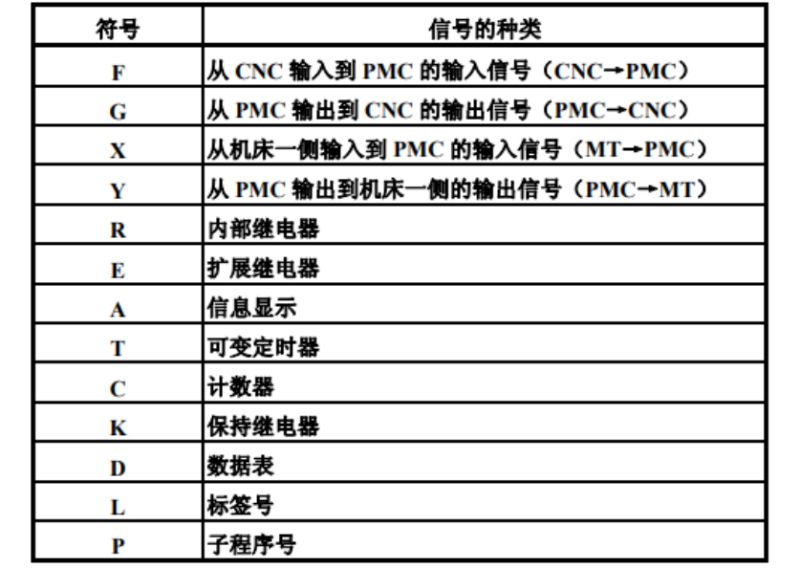
For the address-space conventions used here (R / E / Y / G / F / K / A), see the FANUC PMC signal address reference.
5. Stage 4 — Download and verify
- Transfer the new PMC program to the CNC.
- Verify with the diagnostic tools: open PMCDGN / STATUS and watch each new key’s R bit flip when pressed — see Fanuc 0i-MD PMC Diagnostic Screens (PMCDGN/STATUS/LAD/PARAM) for the four-screen method.
- Use PMC force output (FORCE) to exercise outputs without running the machine — How to Use FANUC PMC Force Output (FORCE).
- Confirm no PMC alarms are raised — Fanuc PMC Alarm Codes Explained.
6. Safety rules (never skip)
- Keep the e-stop chain, over-travel limit and door-interlock hard-wired circuits untouched. PMC logic never replaces a hardware safety loop.
- Test under safe, isolated conditions (remove actuator power or block travel) before any real run.
- Run single-block / dry-run verification; do not declare the panel “ready” until every key and every interlock is confirmed.
- An unverified ladder must never be described as “ready to use”.
7. Related reading on CNCShare
- What Is a PMC in Fanuc? Ladder Logic, Addresses and Scan Time
- FANUC PMC Ladder Diagram Beginner Tutorial
- How to Backup and Restore a Fanuc PMC Program from LADDER-III
- FANUC 数据备份与恢复完整教程 (ALL I/O / BOOT SRAM)
- Fanuc 0i-MD PMC Diagnostic Screens: PMCDGN / STATUS / LAD / PARAM
- How to Use FANUC PMC Force Output (FORCE)
- Fanuc PMC Alarm Codes Explained
- FANUC PMC 信号地址全集 (Y / G / F / T / C / K / R / A)
8. To be updated — notes for later
This article is a living note. Details to be added as the job progresses:
- [ ] Photos of the old / new panel and the CB106 / CB107 wiring.
- [ ] The full cross-reference table (old R → new R) as an appendix.
- [ ] The complete NEW.LAD routine listing.
- [ ] Any model-specific quirks found during verification.
This tutorial was first compiled from wechat field notes and will be expanded over time. It belongs to the 《FANUC PMC 维修学习资料》 series.
Got a problem this article doesn’t answer? Leave a comment below — this article will be updated based on the real questions and cases readers report.
Where to go next
- FANUC Troubleshooting — the full guide library: alarms, diagnosis numbers, servo, spindle, PMC and electrical faults, organised by symptom.
- CNC Repair Tools — which instrument measures what: multimeters, clamp meters, insulation testers and oscilloscopes, with the specification that actually matters.
- Remote Technical Support — have the readings reviewed with you: alarm reverse lookup, PMC ladder analysis and servo tuning advice by call. Repair companies and integrators welcome.
Read the guide, get the right instrument, or walk the diagnosis through with someone — pick whichever you need.

























暂无评论内容