


If you search “FANUC PMC” you will mostly find alarm code tables and parameter lists. That is useful when you are reading a fault code. It is not useful when you are standing in front of a machine trying to figure out why the ladder logic behaved the way it did. This guide is written for that second situation.
A PMC — Programmable Machine Controller — is the PLC that FANUC built into every FANUC CNC 梯形图 system, and understanding its scan time is the difference between reading a program and actually debugging it. It reads inputs, executes your ladder logic from top to bottom, writes outputs, then does it all again. That loop is called the scan cycle, and almost every strange ladder behaviour you will ever meet traces back to it.
本文用英文讲解发那科 PMC 的核心机制,重点是很多维修工程师知道却不真正理解的 scan time(扫描周期)。理解扫描周期,才能解释定时器为什么提前动作、边沿信号为什么会漏、同一段逻辑为什么重启后表现不一样。
What a PMC Actually Is, and What It Is Not
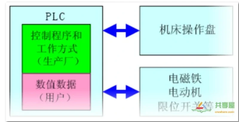
PMC stands for Programmable Machine Controller. It is FANUC’s own flavour of PLC, running on dedicated hardware inside the CNC rather than on a separate PLC rack. Everything you already know from Siemens or Mitsubishi PLC transfers directly — the logic concepts are identical. What changes is the address naming, the programming environment, and the fact that the PMC has a private conversation with the CNC.
| You need to know | FANUC equivalent |
|---|---|
| Ladder instruction | Same vertical power rail, horizontal rung logic |
| Input point | X address |
| Output point | Y address |
| Internal memory bit | R address |
| Timer | TMR instruction |
| Counter | CTR instruction |
| Scan cycle | 8 ms to 32 ms, typically fixed per PMC model |
Two things make a FANUC PMC different from a general PLC and both of them matter for troubleshooting.
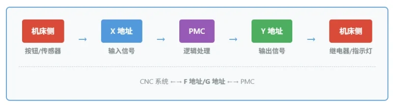
First, the PMC talks to the CNC through dedicated address groups. The CNC sends status into the F addresses and waits for commands in the G addresses. A Y output cannot influence the CNC directly, and a G address has no physical terminal. Writing a Y where you meant a G produces no alarm at all — the signal simply disappears. This is the single most common silent failure in PMC work.
Second, the PMC does not run in real time. It runs in a fixed-length loop. Everything in this guide comes back to that one fact.
The Scan Cycle: How Fanuc PMC Executes Ladder Logic
This is the section most Fanuc ladder diagram tutorials skip, and it is the one that explains the bugs.
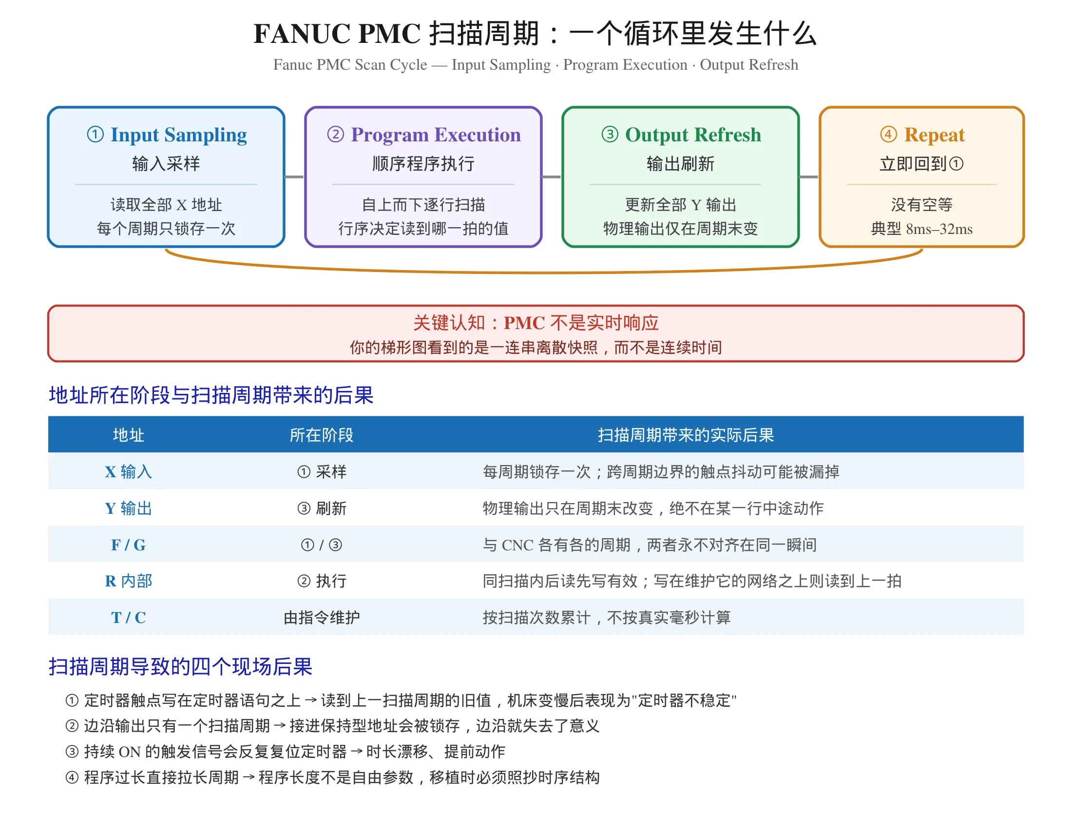
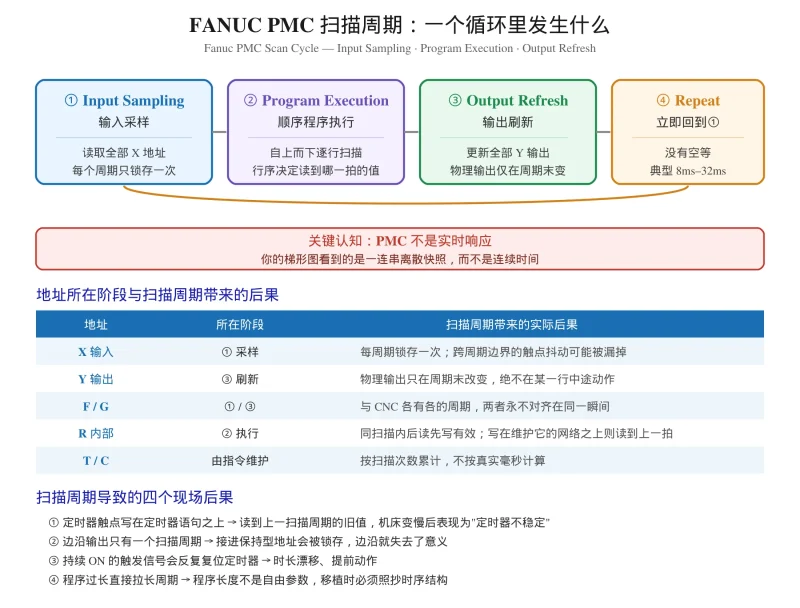
The four stages of every scan
- Input sampling — the PMC reads every X address and latches the current state.
- Program execution — it walks the ladder diagram from the top rung downward, left to right, executing each instruction.
- Output refresh — it writes the updated Y outputs to the machine.
- Repeat — it goes back to step one immediately. There is no idle wait.
Now count what you have learned from stage two. If your program has 200 rungs, and the PMC takes 8 milliseconds for the whole loop, then each individual rung is only being evaluated for a tiny fraction of that 8 ms. Your logic does not see continuous time. It sees a sequence of discrete snapshots, one scan after another.
Why this matters: four consequences you will actually see
Consequence one — a rung written below a timer reads last scan’s value.
The sequential program executes strictly from top to bottom. If you place a rung that reads a timer contact *above* the TMR instruction that maintains it, that rung is reading the value the timer had at the end of the previous scan. On a fast machine the difference is invisible. When the machine slows down, the lag becomes obvious and engineers report it as “the timer is unstable”. The timer is fine. The rung is in the wrong place.
Consequence two — an edge output lasts exactly one scan.
Edge detection instructions such as DIF, DIFU and DIFD produce an output that is valid for a single scan cycle and nothing more. That is correct behaviour, not a defect. If you wire an edge output into a retentive address, the one-scan pulse is latched and loses its entire meaning — you have converted a momentary signal into a permanent one. Learn the difference between DIF and CNT here: CNT is a counter instruction, it is not edge detection.
Consequence three — a constantly ON trigger signal breaks a timer.
A TMR instruction only accumulates time while its input condition stays ON. If the trigger input is a level that remains true, or if it is re-triggered by a noisy contact, the timer resets and starts again. The result is a timer that “drifts” or “sometimes fires early”. Once you start thinking in scans, this failure mode becomes obvious: the input changed state more than once per cycle, and the timer has no way to know which edge you meant.
Consequence four — a program longer than the cycle changes timing.
Program length is not a free parameter. Adding rungs changes the total execution time, and on a busy machine that can push the cycle length toward the limit where the PMC can no longer keep up reliably. This is why experienced engineers copy the timing structure when they port a program between machine models, not just the logic. And this is also why the PMC model, not the CNC model, determines what resources you have to work with.
How to see the scan cycle yourself
Do not take the number from a manual and hope it matches your machine. Read it from the control. On most FANUC systems the PMC execution time is displayed on a PMC or system diagnostic screen together with the ladder status. Check the value, note it, and use it as your baseline whenever you diagnose a timing question.
Scan time and the address layers
| Address group | Lives in which stage | Implication of the scan cycle |
|---|---|---|
| X (input) | Sampled at stage 1 | Latched once per cycle; contact bounce across the cycle boundary can be missed |
| Y (output) | Written at stage 3 | Physical output changes only at cycle end, never mid-rung |
| F (CNC to PMC) | Sampled at stage 1 | CNC signal and ladder logic are never aligned to the same instant |
| G (PMC to CNC) | Written at stage 3 | The CNC reads it in its own cycle, so a G change has additional latency |
| R (internal) | Stage 2 | Shared across every rung in the same scan; read-after-write works, one rung above does not |
| T / C | Maintained by instructions | Counted in scans, not in real milliseconds |
The G row deserves a second look. A G signal travels PMC → CNC, and the CNC samples it on the CNC’s own schedule. So the total delay between “the ladder decided” and “the CNC reacted” is longer than one PMC scan. If you are chasing a machine that lags rather than fails, this additional latency is frequently the explanation.
A Practical Fanuc Ladder Diagram Example
The following describes a typical main spindle start sequence in Fanuc ladder diagram form. It is written as description rather than a literal rung list, because the exact rung format depends on your PMC model and your machine’s address allocation.
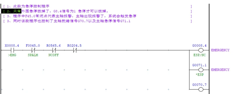
The condition for permitting a spindle start combines four things: the spindle is at rest, the door is closed, the emergency stop chain is healthy, and the spindle is in the forward orientation. All four must be satisfied. Engineers sometimes wire only one of them and are then surprised when the machine starts with the door open — the alarm logic protects what you gave it, not what you meant.
Once permitted, the ladder drives the spindle forward command through a G address, then waits for the CNC to report spindle speed reached through an F address. Only when that confirmation arrives does the ladder release the interlock. Confirmation before release is the pattern behind almost every safe PMC design: never assume the machine did what you asked, wait until it tells you.
If the confirmation never arrives within the expected number of scans, the ladder raises a custom alarm. That is a PMC alarm — written by the machine builder, not by FANUC. Understanding the difference between a system alarm and a builder-written alarm saves a lot of confusion during diagnosis: system alarms you read, PMC alarms you wrote.
Fanuc Ladder III: The Programming Environment
FANUC Ladder III is the FANUC PMC programming software used for 发那科 PMC 梯形图编程. For FANUC PMC programming work it occupies roughly the same position as GX Works for Mitsubishi or TIA Portal for Siemens.
What a maintenance engineer needs from it day to day:
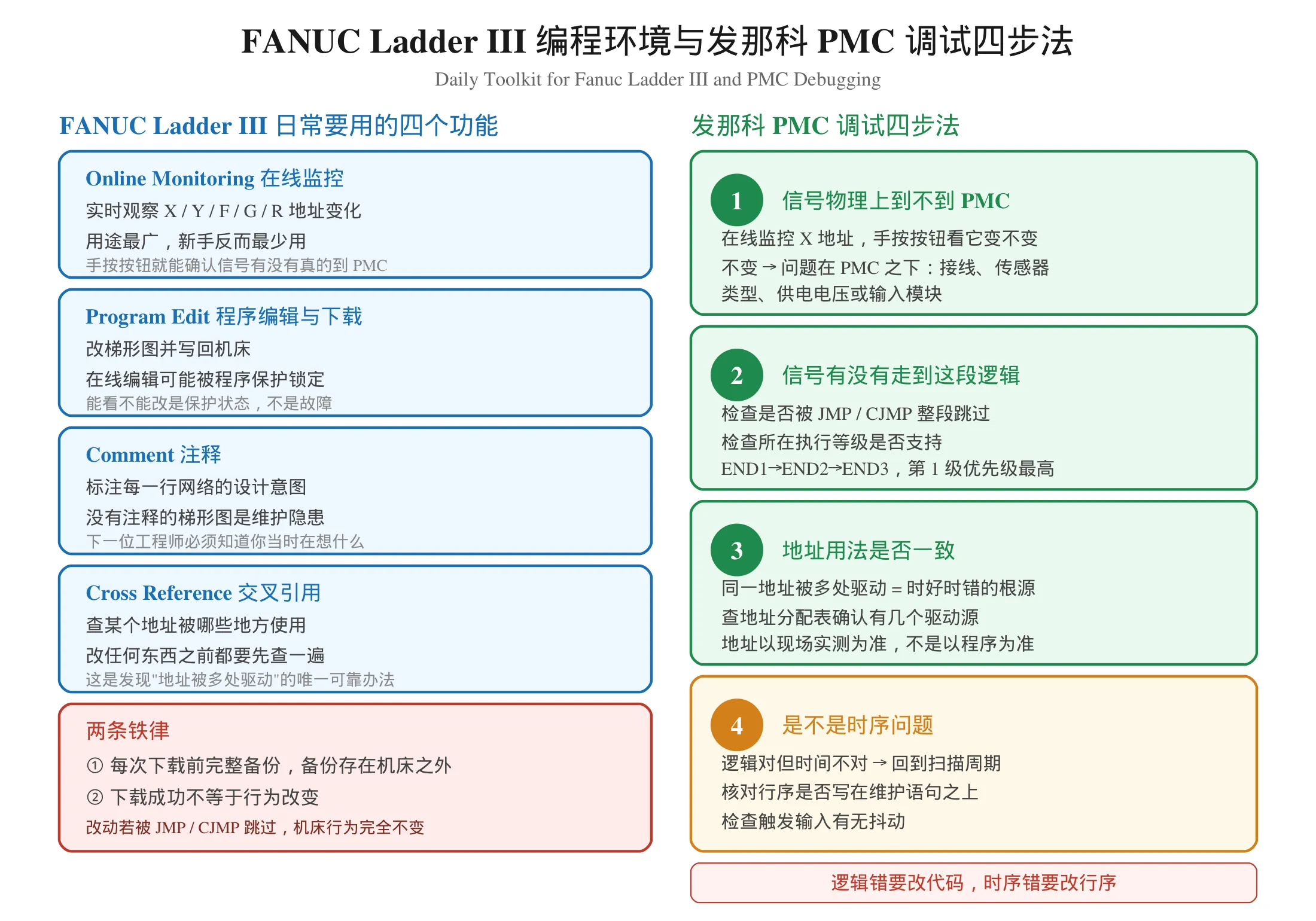
- Online monitoring — watch X, Y, F, G and R addresses live while the machine runs. This is the single most useful feature and the one beginners underuse.
- Program edit with download — modify the ladder and push it back down. Note that editing online may be blocked by program protection; that is a protection state, not a fault.
- Comment and documentation — annotate rungs so the next engineer knows what you meant. A ladder program with no comments is a maintenance liability.
- Cross-reference — find every place an address is used. Use this constantly before changing anything.
对应中文语境下常说的“FANUC Ladder III 梯形图编程环境”,行业内也常直接称为 FANUC Ladder III。Two practical rules. First, back up before every download, and keep the backup outside the machine. Second, remember that a successful download does not guarantee a behaviour change — if the rung you edited sits behind a JMP or CJMP, or you edited a program that is not the one actually running, the machine will behave exactly as before. When writing changes, remember that a CJMP condition must always have a matching fallback JMP, otherwise both branches execute in sequence.
Fanuc PMC Addresses: A Working Reference
This section is a quick orientation for anyone new to the ladder. 关于保持型地址在断电后的行为,可以看 发那科梯形图保持型地址断电不丢详解。For a deeper look at how the groups differ and why mixing them up is so costly, see our dedicated guide on G / R / D 三类易混地址辨析。
| Group | Direction | Purpose |
|---|---|---|
| X | Machine to PMC | Buttons, switches, proximity sensors, limit switches |
| Y | PMC to machine | Relays, indicator lamps, solenoids, contactors |
| F | CNC to PMC | CNC status: M code decode, axis moving, mode signals |
| G | PMC to CNC | PMC commands to the CNC: custom alarms, control interlocks |
| R | Internal | Flow state and interlock flags; retentive across power cycles |
| D / K | Internal | Data registers for counts, positions and comparison values |
The critical discipline here is simple: address the machine, not the program. When a signal is not working, confirm the address from the electrical drawing and a physical measurement first, then look at the ladder. Reversing that order — reading the ladder and assuming the address is right — is how an address mismatch turns into a week of rewriting working code.
Fanuc PMC Debugging: A Working Method
When a Fanuc PMC debugging session stalls, resist the urge to rewrite the rung. Work through the layers in order.
Step 1 — does the input physically exist?
Use Fanuc Ladder III online monitoring on the X address. Press the button by hand. If the address does not change, the problem is below the PMC: wiring, sensor type, supply voltage, or a physical input module. No amount of ladder editing will help.
Step 2 — is the signal reaching the logic?
Check whether the ladder rung is even being executed. A JMP or CJMP can skip it entirely. Some PMC functions only execute at particular levels of the END1 / END2 / END3 sequence, so a rung placed at an unsupported level fails silently. This silent-failure pattern is the same one described in our guide to online editing and program protection.
Step 3 — is the address used consistently?
Multiple drivers for one address produce intermittent behaviour that no amount of testing will pin down. Build or read the machine’s address allocation table and confirm how many sources drive each address. If more than one, you have found your bug.
Step 4 — is it a timing question?
这一步就是发那科 PMC 调试里最典型的时序分支。
If the logic is correct but the timing is wrong, go back to the scan cycle. Check the rung order against the instruction that maintains the value, check the trigger input for chatter, and confirm how many scans the sequence actually needs.
For systematic case studies, see our PMC troubleshooting articles covering five classic field failures。想系统看排障思路,可以读 FANUC PMC 故障排查实战 5 案例;想知道保护相关问题,看 FANUC PMC 在线编辑失效与程序保护解除;定时器和计数器两类最常见故障分别见 FANUC PMC 定时器不动作与提前动作排查 和 FANUC PMC 计数器 CTR 指令详解。
Where to Learn More
Start from the fundamentals and build up in this order:
- Concept — what the PMC is, what the scan cycle is, how signals move between CNC and machine
- Addresses — X / Y / F / G / R and the consequences of using the wrong group
- Software — install Fanuc Ladder III and practise online monitoring on a powered-down machine
- Reading a program — follow a real spindle or tool change sequence rung by rung
- Basic instructions — TMR for time, CTR for counts, JMP/LBL for flow, DIF for edges
- Writing — interlock logic and custom alarms, verified in dry-run before production
视频教程可以从这篇看起:零基础学习发那科 PMC 视频教程全攻略。
系统性的学习资料推荐:FANUC PMC 维修学习资料。
Summary
A PMC is a PLC, and the ladder logic you already know will run on it. What makes Fanuc PMC work different from a general PLC is the address naming and the CNC interface. What makes it hard to debug is the scan cycle: a discrete loop with no idle wait, in which your rung order, your trigger edges and your timing assumptions all matter.
从中文视角说,发那科梯形图编程里绝大多数”莫名其妙”的问题都能这样解释。Almost every Fanuc ladder diagram puzzle — the timer that fires early, the edge that never arrived, the output that changed a scan too late, the machine that behaves differently after a restart — resolves the same way. Find the scan, find the rung order, find the multiple driver.
如果你是刚开始接触发那科梯形图的工程师,建议先把这篇的基础打牢,再往下看指令层面的内容。想系统学习的话,可以从 零基础学习发那科 PMC 视频教程全攻略 开始。
If you are new to 发那科梯形图 programming, begin with the address groups and the scan cycle, then move on to the instructions. Getting those two foundations right prevents far more problems than any later technique will cause. 这也是为什么本站把 PMC 梯形图编程 系列拆成多个专题分开讲——概念、地址、指令、故障排查各占一篇,互相引用而不重复。
Safety note: any change to PMC ladder logic counts as a machine control program change. Work with the machine stopped, back up the original program before downloading, and verify through dry-run, single-block, semi-automatic and then automatic cycle before returning the machine to production. Alarm and interlock logic must never be verified for the first time while a workpiece is being cut.
Disclaimer: the timings, address groups and behaviours described here follow the general architecture of FANUC PMC systems. Specific scan times, available address ranges and supported functions vary by PMC model and CNC series. Confirm every value against the official manual for your machine and verify on site. Examples here illustrate engineering principles only and are not a ready-to-run configuration.














暂无评论内容