


Every Fanuc PMC alarm code guide on the internet starts the same way: a long table of numbers. PS0001, PS0100, SR2000, and hundreds more, listed with their meanings. That table is genuinely useful — but only after you already know which layer the alarm came from. Get that wrong and you will spend an afternoon looking up a code that was never the problem.
FANUC Ladder III 的在线监控是这套流程里最关键的工具。This guide takes the opposite approach. It starts where a maintenance engineer actually starts: the machine has stopped, there is a fault code on the screen, and you need to get production running again. We cover how to identify the alarm layer, how to find the definition, how to trace it back to a physical cause, and how to clear it properly without leaving a second fault behind.
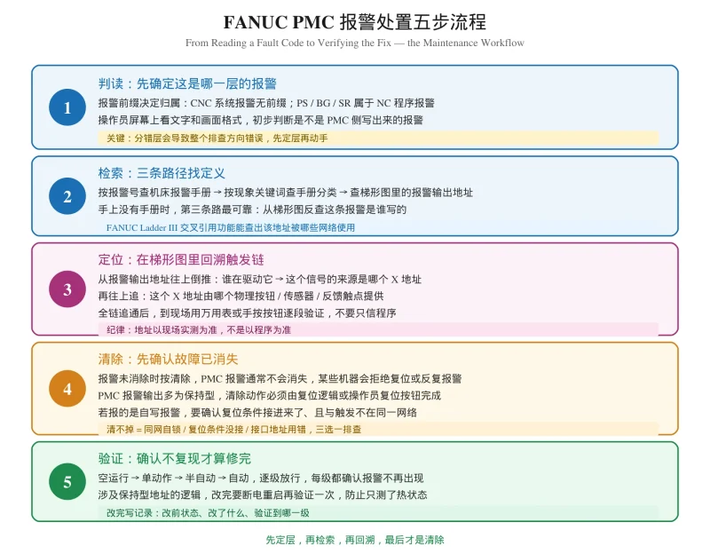
这就是发那科梯形图里 PMC 报警的实战处置流程。市面上讲报警代码的文章基本都是一张代码表,但代码表解决不了”该查哪张表”这个问题。本文按维修现场的实际操作顺序讲:先判读属于哪一层报警,再检索定义,然后回到梯形图回溯触发链,最后才是清除和验证。
Why PMC Alarms Are Different From CNC System Alarms
This distinction decides the entire direction of your troubleshooting. On a FANUC machine, an alarm can come from three distinct places, and they behave in completely different ways.
| Alarm source | Written by | Can you change it? | How to investigate |
|---|---|---|---|
| CNC system alarm | FANUC factory | No | Look it up, replace the hardware it points to |
| NC program alarm (PS / BG / SR) | FANUC factory | No | Check the program against the code meaning |
| PMC alarm | You, the machine builder | Yes | Trace it in the ladder and the machine |
对发那科 PMC 调试来说,The practical difference is this. A factory alarm tells you something is broken and gives you a code to look up. A PMC alarm tells you someone decided this condition is worth stopping the machine for — and that decision, and the condition behind it, lives in your ladder diagram.
We already covered how to write PMC alarms in our guide on custom Fanuc PMC alarm codes. This article is about the other side of that: what you do once one appears on the screen. If you are new to 发那科 PMC 调试 and have not yet built a working knowledge of the address groups, start with the fundamentals instead.
Step One: Read the Alarm Before You Search It
Before you open any manual, spend thirty seconds reading what the machine is actually telling you.
The prefix is the layer
- No prefix, numeric code only → CNC system alarm. Something inside the CNC, the servo system or the hardware detected an error.
- PS, BG or SR prefix → NC program alarm. PS relates to the running program, BG to background editing, SR to communications.
- Custom message and alarm number, often Chinese text → very likely a PMC alarm written by the machine builder.
For a quick reference on factory alarms, our Chinese-language tables cover FANUC 系统严重错误报警代码大全 and FANUC 基本报警代码大全(PS / BG / SR 报警号速查表). Neither of those covers PMC-level alarms, which is exactly the gap this article fills.
Note what the machine was doing — 这就是标准的 FANUC PMC 调试现场记录习惯
Record three things before you touch anything:
- What mode was the machine in — automatic, MDI, manual, edit
- What action was in progress — tool change, spindle start, return to reference
- Whether the fault is intermittent or consistent
从 FANUC CNC 梯形图 维护的角度看,第三点比工程师预期的更重要。The third point matters more than engineers expect. An intermittent alarm that only appears on rapid traverse is almost never a bad sensor — it is a timing or chatter problem. One that appears every time you press the same button is a wiring or interlock issue. Deciding this on the spot saves you from chasing the wrong category entirely.
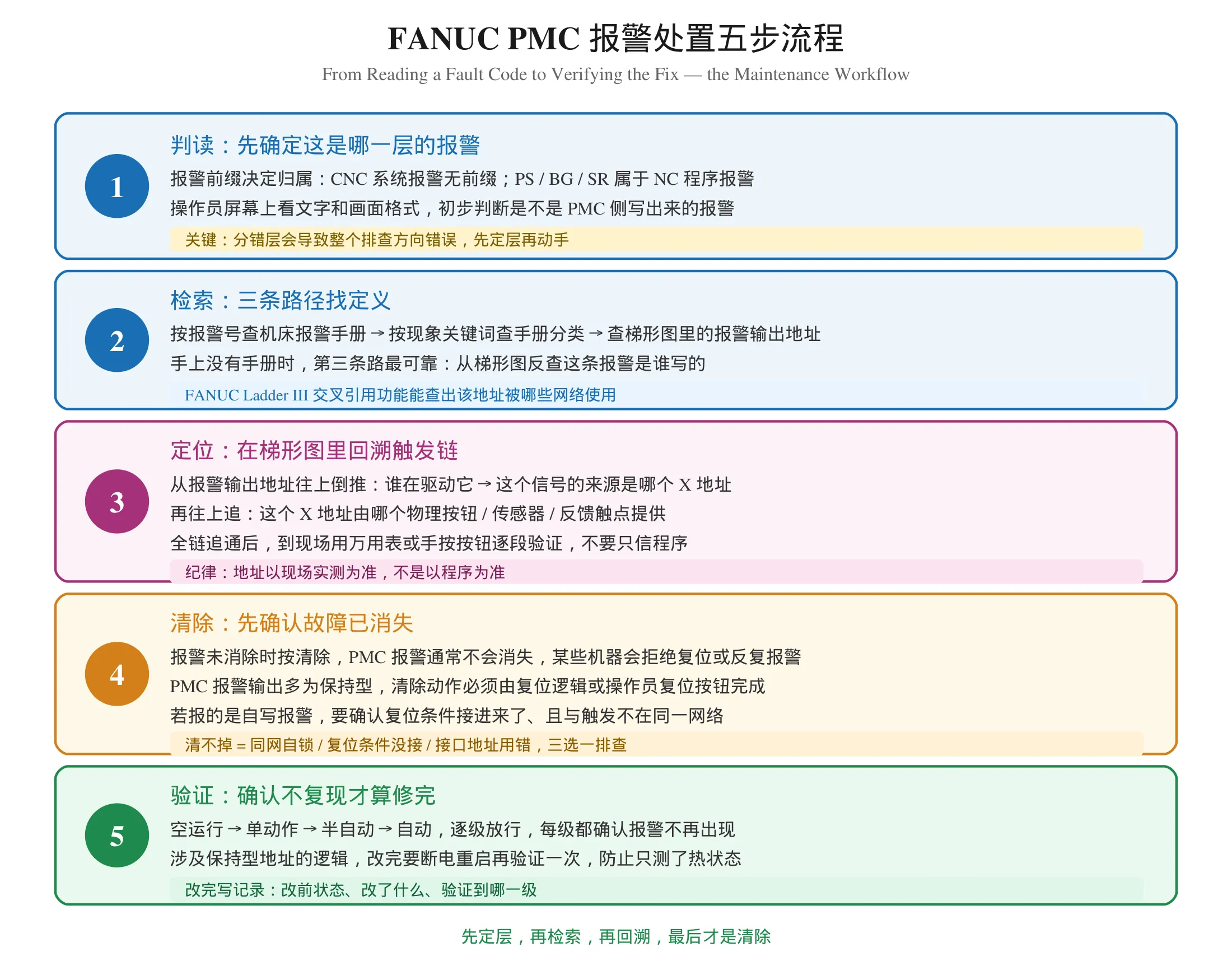
Step Two: Search for the Definition, Three Routes
There are three ways to find out what a PMC alarm means, and they are not equally reliable.
Route 1 — the machine’s own alarm manual
If the builder documented the machine properly, this is the fastest. The manual maps alarm numbers to plain-language descriptions, usually organised by subsystem: spindle, tool magazine, lubrication, safety.
If the machine has no alarm manual, that tells you something important about how it was built. Every PMC alarm on that machine was written by someone who assumed the reader already knew what it meant.
Route 2 — search by symptom rather than by number
When you do not have a manual, search the manual you do have by what you observed, not by the code. “Tool magazine door” will find the right page far faster than hunting for the number in a table.
Route 3 — read it back out of the ladder
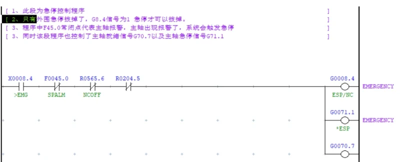
This is the most reliable method and the one most people never try. 换句话说,报警内容就写在 FANUC PMC programming 的梯形图里,不用猜。 The alarm is in your Fanuc ladder diagram, so open FANUC Ladder III and find the rung that drives the alarm output.
The trace works backwards:
- Find the alarm output address the machine is displaying
- Find which rung writes to it
- Read the contact condition that triggers that rung — this is your input X address
- Look up that X address in the machine’s address allocation table to find the physical device
- Go to the machine and verify that device
In Fanuc Ladder III, the cross-reference function answers step two in seconds: enter the address, and it lists every rung that uses it. If more than one rung appears, you have already found your problem — multiple drivers on one address is the direct cause of intermittent faults.
Step Three: Trace the Trigger Chain in the Ladder
Once you know which address the alarm fires on, work backwards until you reach a physical component.
A typical tool change interlock chain looks like this:
Magazine at position (F or X)
  → Tool clamp confirmed (X)
    → Spindle stopped (F)
      → Magazine door closed (X)
        → Interlock satisfied (R flag set)
          → Alarm released
Read that chain in the ladder and you can usually name the failed component before you touch a multimeter. Then confirm it physically: press the button by hand, or measure at the terminal.
The discipline that matters: address the machine, not the program. The correct order is electrical drawing and address table → physical measurement → ladder program. Reverse it and you will rewrite working code to fix a wiring fault. We covered this in detail in our guide to diagnosing X and Y address mismatches.
One more layer worth checking here: scan order. If the ladder logic is correct but the timing is wrong, the problem is usually that a rung is written above the instruction that maintains the value it reads. That is a scan-time issue, not a logic issue, and no amount of rewiring will fix it.
Step Four: Clear the Alarm Properly
This is where most troubleshooting guides stop, and where a lot of machines end up in a worse state than before.
Never clear an alarm before the fault is gone
If the fault condition still exists, clearing the PMC alarm does nothing useful — it either refuses to clear, the machine rejects the reset, or the alarm returns within a cycle or two. Pressing reset repeatedly on a live fault is not a fix, it is noise.
PMC alarm outputs are usually retentive
This is the key behavioural difference from a CNC system alarm. A system alarm clears itself when the cause disappears. A PMC alarm generally latches: once it is set, it stays set until something explicitly resets it, even after the triggering condition has vanished.
That something is either a dedicated reset rung in the ladder, or the operator’s alarm reset button. Both are legitimate designs, and which one your machine uses depends on how the builder wrote it.
If the alarm will not clear
Three causes account for nearly every case:
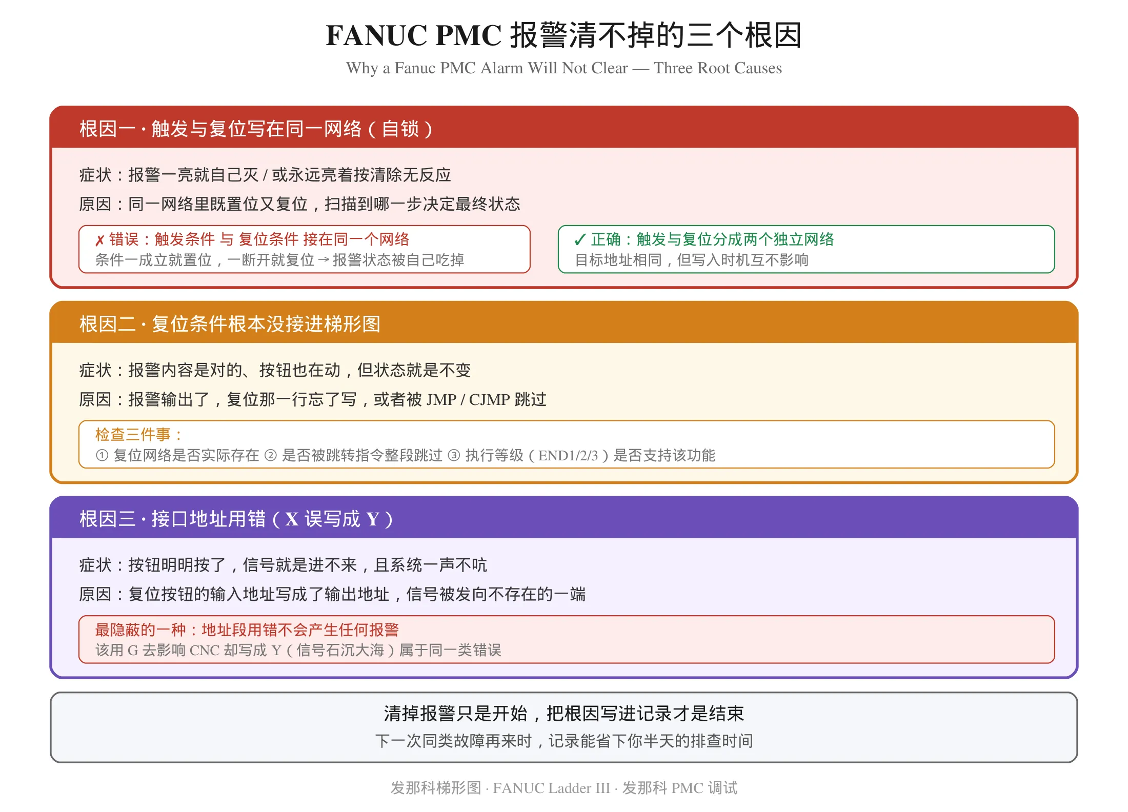
Same-network self-locking. The trigger condition and the reset condition were written into the same rung network. The scan order then decides the final state, and the alarm either latches permanently or extinguishes itself the moment it appears. The rule is absolute: trigger and reset must not share a network.
The reset condition was never connected. The alarm output was built correctly and the reset button moves, but nobody wrote the rung that resets the alarm address. Or it exists but sits behind a JMP or CJMP that skips it. Or it is at an END1 / END2 / END3 level that does not support the function. Remember that level 1 has the highest priority, and some functions exist only at level 3.
Wrong interface address. The operator reset button’s input address was written as an output address. The signal is being sent to a place that does not exist, and — critically — the machine raises no alarm at all. This is the same class of silent error as writing a Y where you meant a G.
Step Five: Verify It Does Not Come Back
Clearing the alarm proves nothing. A fault is only fixed when it stays gone.
Work through the levels in order, confirming at each one that the alarm does not return:
- Dry run — every axis at rapid, nothing cutting
- Single block — step through the exact sequence that failed
- Semi-automatic — one cycle, monitored
- Automatic — several consecutive cycles
If the machine uses retentive addresses in the logic you changed, power-cycle it and verify again. Logic that works in a warm state can still be wrong after restart, because a retentive address carries its pre-shutdown value through the power-up moment. This is a frequent source of “it worked yesterday” failures.
Then write down what you did. What state the machine was in, what you changed, and which verification level you reached. The next engineer who meets the same fault will thank you.
Where PMC Alarms Sit in the Address System
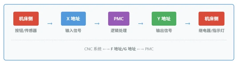
A short reference on how alarm signals move, since this determines what you can and cannot do about them.
| Address group | Direction | Role in alarm handling |
|---|---|---|
| X | Machine to PMC | The physical condition that triggers the alarm |
| Y | PMC to machine | Resets, indicator lamps, buzzer for an active alarm |
| F | CNC to PMC | CNC status that forms part of the trigger condition |
| G | PMC to CNC | Custom alarm output to the CNC display — the standard path |
| R | Internal | Interlock flags; often retentive across power cycles |
| D / K | Internal | Alarm counters, retry counts, last-error records |
One caution worth repeating. A PMC alarm reaches the operator screen through the G address group. A Y output has no path to the CNC display at all. If your custom alarm is not appearing, verify it is written to a G address rather than a Y. The detailed reasoning is in our article on G / R / D address types and how they differ.
Building a Maintenance Process That Scales
Individual alarm knowledge ages badly. Machines get modified, builders change, personnel move. What survives is a process.
Keep an alarm number allocation table. One physical fault, one alarm number. 这也是 PMC 梯形图编程 的基本规范。 When someone wants to add a new alarm, the first step is checking whether the number is free. Without this record, two rungs eventually claim the same number and the second one silently overwrites the first.
Keep the custom alarm text with the customer. A PMC alarm only makes sense to the person who wrote the trigger condition. If that person leaves, the alarm becomes unreadable. The text should say what the phenomenon is, under what condition, and what to check — not “contact the manufacturer”.
Verify against the machine, not the manual. Documentation drifts. Confirm addresses at the machine.
Log every alarm you clear, with the root cause. This is the single highest-value habit. A machine with three years of fault history is a machine you can maintain; a machine without one you troubleshoot from scratch every time.
Where to Learn More
If you are building your 发那科梯形图 foundation, work through this order:
- What the PMC is and how the scan cycle works — the foundation everything else depends on
- Address groups — X / Y / F / G / R and what happens when you use the wrong one
- Software — FANUC Ladder III and online monitoring on a powered-down machine
- Reading a program — follow a real tool change sequence rung by rung
- Writing — interlock logic and custom alarms
Video walkthroughs start here: 零基础学习发那科 PMC 视频教程全攻略。
Systematic reference material: FANUC PMC 维修学习资料。
For worked examples of real faults, see our five-case PMC troubleshooting series at FANUC PMC 故障排查实战 5 案例, and for the timer and counter faults that generate the most alarms, FANUC PMC 定时器不动作与提前动作排查 and FANUC PMC 计数器 CTR 指令详解.
Summary
Reading a Fanuc PMC alarm code is a three-step discipline, and the order is what separates a ten-minute fix from a lost afternoon.
Identify the layer first. System alarm, NC program alarm, or PMC alarm. A factory code points you to a manual. A PMC alarm points you to a ladder rung.
Then search, then trace. Manual by number, manual by symptom, or — most reliable — read the definition straight out of the Fanuc ladder diagram using cross-reference.
Then clear and verify. PMC alarms usually latch, so clearing is a separate action from the fault itself. Clear only after the cause is gone, and verify through dry run, single block, semi-automatic and automatic before releasing the machine.
When it will not clear, there are only three real reasons: trigger and reset in the same network, the reset condition never connected, or an input address written as an output. Check those three and you will have the answer.
故障清掉只是开始。把根因写进记录,下一次同类故障就能省下你半天的排查时间。
Safety note: clearing a PMC alarm does not make a machine safe. The alarm is a symptom, not the fault. Never bypass an interlock or an alarm to keep production running — the interlock exists because the consequence of ignoring it is a damaged machine, a scrapped workpiece, or an injured operator. Verify the actual condition before returning the machine to service.
Disclaimer: alarm number ranges, address allocation and display behaviour vary by CNC series, PMC model and machine builder. Nothing in this article specifies concrete alarm numbers or address codes; every value must be confirmed against the official manual for your machine and verified on site. The workflows described are general engineering practice, not a configuration to be copied directly into a machine.














暂无评论内容