


Most Fanuc ladder diagram troubleshooting happens somewhere other than where you expect it. The fault is on screen, the button clearly works, the program downloaded without error — and the machine still does the wrong thing. At that point the ladder program is not where the problem is. The problem is in a screen you may not know exists.
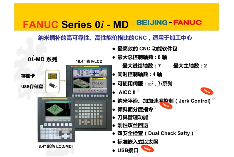
On a FANUC 0i-MD, the PMC diagnostic screens are the tool for exactly this situation. Engineers type PMCDGN into the machine and open four layers of information, each answering a different question. Almost nobody outside FANUC service teaches this layer-by-layer, which is why 搜索 “PMCDGN” 的人 基本都在找中文资料里根本没有的东西。
中文说法通常叫「PMC 诊断画面」或「PMC 诊断屏」,而现场工程师更习惯直接敲英文缩写。FANUC Ladder III 属于外部编程软件,但很多问题在连电脑之前就能解决——机床自带的这几层诊断画面,往往比任何软件都快。
Why the Machine’s Own Screens Come First
Reach for Fanuc Ladder III when you need to edit, download or cross-reference. Reach for the control’s own diagnostic screens when you need to find out what is happening.
对做 FANUC CNC 梯形图 维护的人来说,这两者分工很明确:Ladder III 用来改,机床自带画面用来查。The difference in practice is speed and certainty. With the control, you are looking at live machine data with no connection delay and no risk of disturbing the program. Every value shown is the value the PMC is actually using.
For 发那科 PMC 调试 而言,这四层画面的顺序就是排查顺序本身——从外往内逐层深入,先看 PMC 跑没跑,再看信号到没到,再看逻辑走没走到,最后才动参数。
One caution before you touch anything
The screens described here are diagnostic views. Some parameters on the PARAM layer are read-only, some are writable, and the writable set differs by PMC model. Do not change a parameter to see what happens. Write down and photograph the current values before any edit, confirm the item is actually writable on your machine, and check the range against the official manual for your specific control.
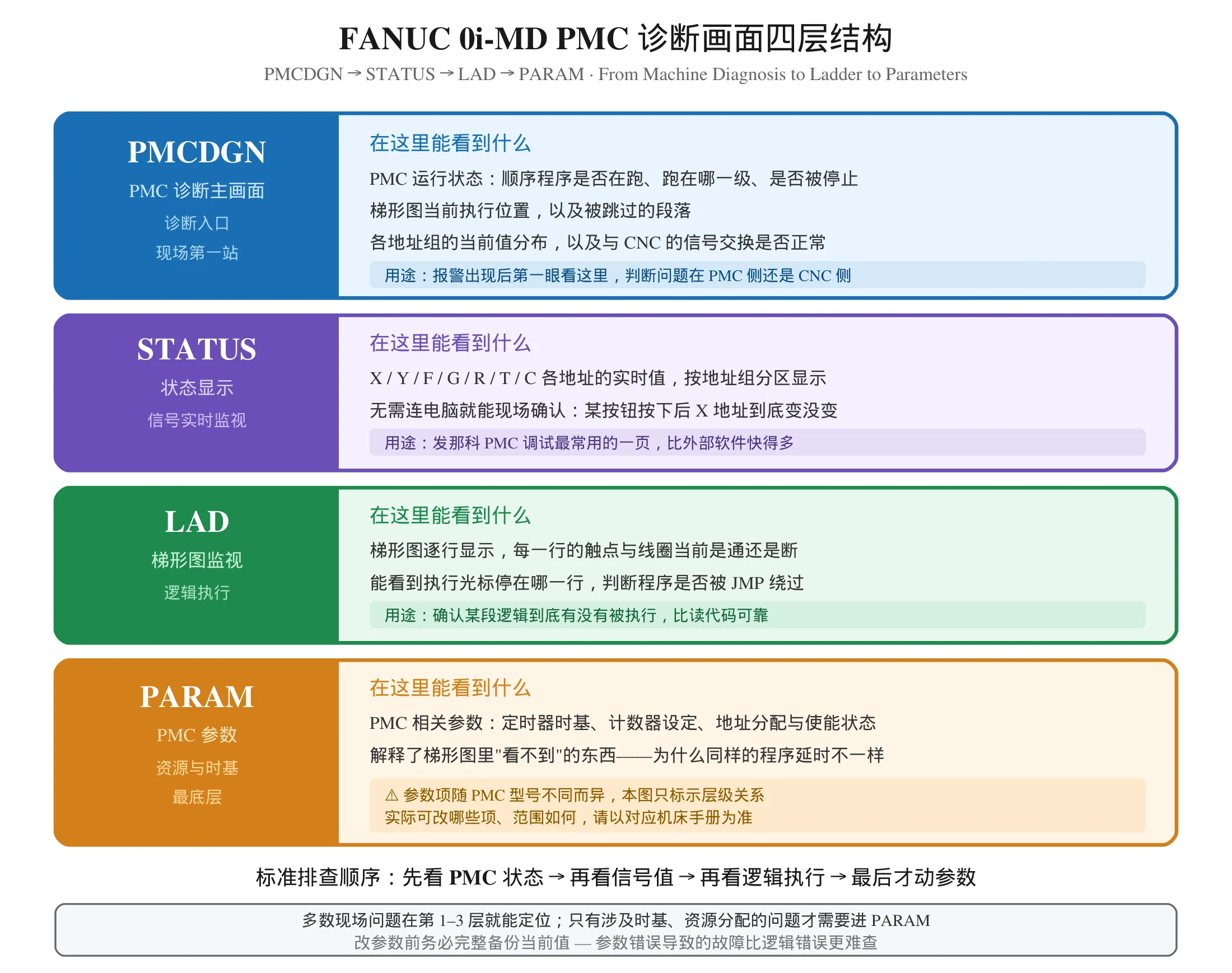
Layer One: PMCDGN — The PMC Diagnostic Main Screen
FANUC PMC 诊断的第一站。PMCDGN is the entry point. Everything else on this guide is reached from it.
What it tells you
Whether the PMC is running at all. A stopped or halted sequential program is the single most common cause of “the machine does nothing”. This is the first thing to check and the most commonly skipped one.
Which execution level is active. The sequential program runs in a fixed order — END1, then END2, then END3, then back to END1. Level 1 has the highest priority. If a rung lives at a level that does not support the function you are using, it silently never runs, and nothing on the control will tell you why.
The current execution position in the ladder. Where the program pointer is right now tells you a great deal. If the pointer never reaches the section you believe it should, something is jumping over it.
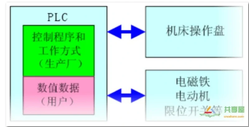
PMC to CNC signal exchange status. This answers whether the two sides are talking at all — a fast way to decide whether a problem belongs to the PMC or to the CNC.
When to use it
FANUC PMC troubleshooting always starts here. Start here for every unexplained fault. It takes thirty seconds and it eliminates an entire class of problems: those where the logic is fine but the program is not running.
Layer Two: STATUS — Live Address Values
这是 PMC 梯形图编程 之外最值得掌握的一页。STATUS shows the current value of addresses grouped by type. This is the screen that answers “is that signal actually reaching the PMC?”
What it tells you
Values for the interface and memory address groups — machine inputs, machine outputs, CNC status, PMC-to-CNC, internal relays, and the timer and counter areas. Displayed live, updating as the machine runs.
The most useful thing on the whole control
Watch an X address while you press its button.
If the address does not change, the problem is below the PMC entirely: wiring, sensor type, supply voltage, or a failed input module. No amount of program editing will help, and this single test saves engineers hours of pointless searching.
If the address does change, the signal arrived. Now you know the fault is in the logic or the output side, and you move to LAD.
A second use worth knowing
Monitoring Y addresses while operating the machine by hand will often reveal an interlock that is holding the output off. You can see exactly which rung is blocking it once you switch to the ladder view.
关于地址组本身的区别,X / Y / F / G / R 各自的用途和用错的后果,见 G / R / D 三类易混地址辨析。
Layer Three: LAD — Watching the Ladder Execute
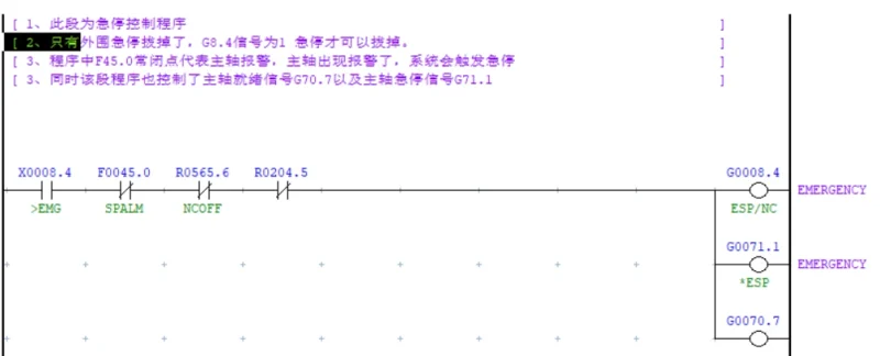
这是 FANUC PMC 诊断里最有价值的一层。LAD displays the ladder program as it runs, showing each rung’s contacts and coils live.
What it tells you
Every contact and coil, in real time. If a contact you expect to be closed reads open, the upstream condition is not satisfied. If a coil you expect to be energised reads off, the rung is not being executed.
The execution pointer. This is the reason LAD exists. When a program behaves as if a section does not exist, this is where you find out whether it is being skipped.
The download-succeeded-but-nothing-changed problem
This is the most common misleading symptom in Fanuc PMC programming. You edit a rung, you download it, the download reports success — and the machine behaves exactly as before.
Two explanations account for most of these cases:
The section is skipped by a jump. A JMP or CJMP condition is true, so the sequential program never reaches your rung. The LAD view shows the pointer moving past it.
You are looking at the wrong program. Some controls run more than one ladder, and the one you edited is not the one executing.
A related trap worth remembering: a CJMP condition must always have a matching fallback JMP. Without it, both branches execute in sequence rather than choosing one, and the resulting behaviour looks like the program is doing things twice.
Layer Four: PARAM — The Time Base and Resource Settings
FANUC PMC programming 里最容易漏掉的一环就是这一层。PARAM is the deepest layer, and the one most people never need. When you do need it, however, nothing else will tell you what it knows.
What it tells you
PMC configuration items: time base settings for timers, counter configuration, address allocation, enable and disable flags for functions. The exact item numbers and ranges depend on the PMC model — look them up in the manual for your machine rather than assuming a numbering.
Why this layer matters: the time base
This is the single most valuable thing PARAM can explain. In a TMR instruction, the preset value written in the ladder diagram is not a time. Real delay equals preset value multiplied by the time base, and the time base lives in the parameters. Change it and every timer in the program changes speed, with no visible change to the ladder at all.
That is why a timer can behave correctly on one machine and run long or short on another with an identical program. It is also why anyone who copies a timer preset value from another machine without checking the time base is working blind. The full explanation is in our guide to the TMR instruction and time base selection.
Other things only PARAM can tell you
Whether a function is enabled at all. Some PMC functions require a parameter to be active before the ladder instruction will do anything.
How much of each resource exists. 这直接决定了跨机型移植时哪些梯形图能抄、哪些抄了会出问题。 Timer and counter counts, available address ranges. If you are porting a program and a rung references a timer that does not exist on the target, PARAM is where you discover that. We covered this in detail when comparing PMC resources across the 0i-MD and 0i-MF.
Never change a parameter you have not read first
Record every value before editing, change one item at a time, and verify the effect before touching the next. A parameter error is much harder to diagnose than a ladder error, because the ladder still looks correct.
Putting the Four Layers Together
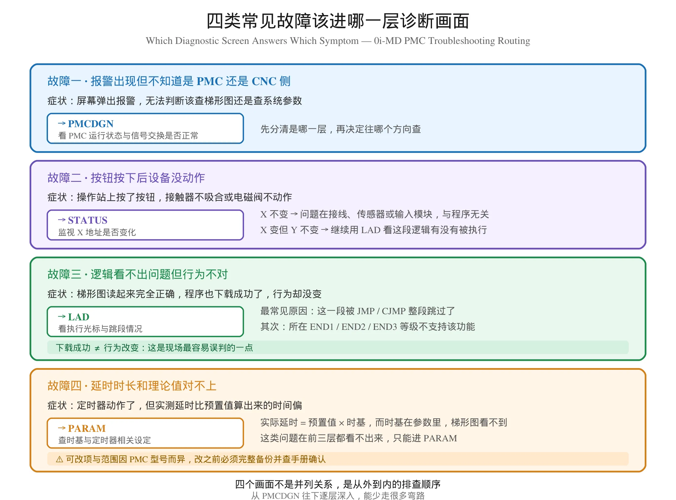
从 FANUC CNC 梯形图 排障角度看,The value of this system is the order. Most faults resolve within the first three layers, and PARAM is reached only when the symptom points specifically at timing or resource allocation.
| Symptom | Go to | What you are looking for |
|---|---|---|
| Alarm, cannot tell which side is at fault | PMCDGN | Is the PMC running, is signal exchange alive |
| Button pressed, nothing happens | STATUS | Does the X address change when pressed |
| Ladder reads correctly, behaviour wrong | LAD | Is the section skipped, is the level supported |
| Timer runs long or short | PARAM | The time base setting |
A worked example
A spindle fails to start. The ladder rung reads correctly and the start button works.
PMCDGN — the PMC is running, the execution level is normal, signal exchange with the CNC is alive. The problem is not a stopped PMC.
STATUS — the spindle start X address changes when the button is pressed. The signal reached the PMC.
LAD — the interlock contact feeding that rung is open. Following it back, the “spindle stopped” condition is not satisfied, so the interlock holds.
Back to STATUS — the spindle-stopped feedback from the CNC is absent, which points at either the F address group not receiving CNC status, or a physical spindle condition that is genuinely not satisfied.
Two more layers: check the ladder trace for a jump instruction over that rung, then check the address allocation to confirm the F address is assigned on this machine. A ported program that references an address not configured on the target behaves exactly like a missing signal.
Discipline that keeps this efficient
Check the machine, not the manual. Documentation drifts from reality; the control does not. Confirm addresses and parameter values on the machine itself.
Work top-down through the layers. Starting at PARAM when the real answer was in STATUS wastes more time than it saves.
Photograph diagnostic screens. A photo of STATUS or PARAM is a far better record in your maintenance notes than a page of hand-written values.
地址以现场实测为准,不是以程序为准 — this is the discipline behind it. Address the machine, not the program. The correct order is electrical drawing and address table → physical measurement → ladder program. The reasoning behind this discipline is covered in our guide to diagnosing X and Y address mismatches.
Where to Learn More
If you are building your 发那科梯形图 skills, this is the natural order:
- What the PMC is and how the scan cycle determines timing — the foundation
- The diagnostic screens in this article — how to read live machine state
- Address groups — X / Y / F / G / R and what happens when you use the wrong one
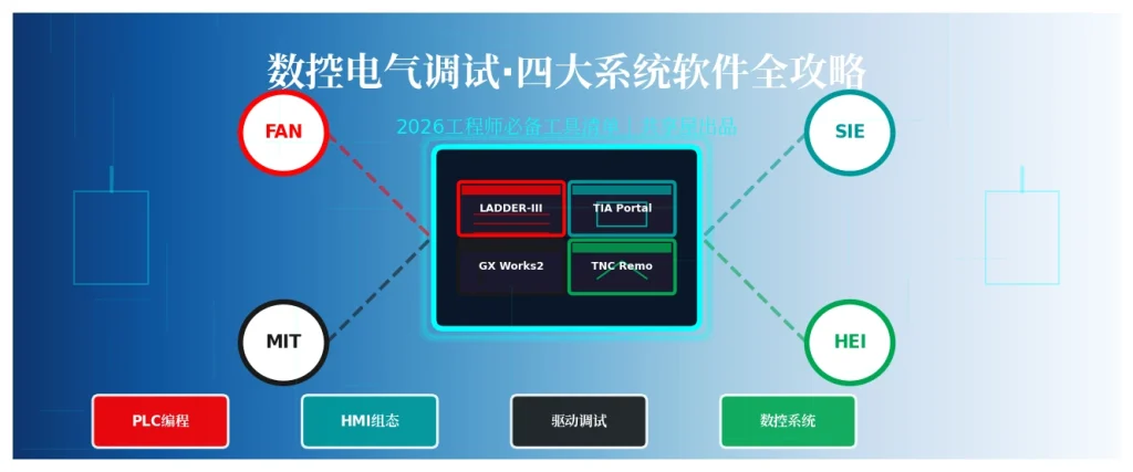
- Software — FANUC Ladder III for editing, downloading and cross-referencing
- Reading a program — follow a real tool change sequence rung by rung
- Writing — interlock logic and custom alarms, verified before production
发那科梯形图 学习可以按这个顺序推进。Video walkthroughs start here: 零基础学习发那科 PMC 视频教程全攻略。
Systematic reference material: FANUC PMC 维修学习资料。
For case studies and specific failure modes, see our five-case PMC troubleshooting series at FANUC PMC 故障排查实战 5 案例, and for the machine-model resource differences mentioned above, FANUC 0i-MD / 0i-MF PMC 差异对比;报警出现后的处置流程见 Fanuc PMC 报警代码读取检索与清除,扫描周期对时序的影响见 What Is a PMC in Fanuc? Scan Time。
Summary
The four diagnostic screens on a FANUC 0i-MD are a layered answer to a layered question.
PMCDGN answers “is the PMC running and talking to the CNC”. STATUS answers “is that signal actually here”. LAD answers “is that logic actually executing”. PARAM answers “why does the same program produce a different time”.
Used in that order, they resolve most Fanuc PMC faults without ever connecting a laptop. Used out of order — or skipped in favour of guessing at the program — they turn a short repair into a long afternoon.
对发那科 PMC 调试 而言,掌握这四层画面比会写多少条梯形图更有价值。因为梯形图是你写的,而诊断画面告诉你的是机床此刻真实发生的事。
Safety note: diagnostic screens show live machine state. Do not operate controls while browsing them unless the machine is in a safe mode and you are qualified to do so — a machine in manual mode with the door open can still move axes. Never change PMC parameters on a machine that is required for production without a verified backup of every value you touch, and never change them to “see what happens”.
Disclaimer: screen names, layout and available parameters vary between CNC series, software versions and PMC models. The item numbers, ranges and writable sets on the PARAM layer in particular differ by machine; confirm every value against the official manual for your control before making any change. Nothing in this article specifies concrete parameter numbers. The workflows described are general diagnostic practice, not a configuration to be copied directly into a machine.












暂无评论内容