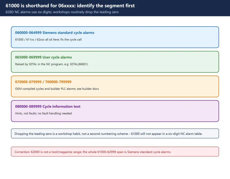



Short answer:
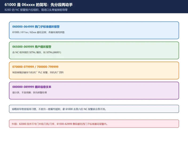
61000/62000in five-digit form belong to the06xxxxband — Siemens standard cycle alarms (drilling, milling, turning, measuring/probing cycles), commonly written61000–62999in full;065000–069999is the user-cycle alarm range, triggered from the NC program withSETAL(for exampleSETAL(66001));- Both types are overwhelmingly caused by a missing or contradictory cycle parameter, so the fix is in the cycle call, not in the machine hardware.
Segment rules here reflect common 828D software versions. Alarm texts and individual numbers vary by control, cycle version and builder customisation — always use the full alarm text on your HMI and the diagnostics manual shipped with that machine. Any verification involving axis motion requires no workpiece, no personnel and no interference in the working area.
30-second check: number to owner
| Number you see | Full range | Owner | Check first |
|---|---|---|---|
| 61000 / 611xx / 62xxx | 060000–064999 | Siemens standard cycles | Cycle call and parameter fields |
| 65xxx | 065000–069999 | User cycles (SETAL) | Your / builder's cycle program |
| 7xxxxx | 070000–079999 / 700000–799999 | OEM compiled cycles / builder PLC | Builder manual and ladder |
| 8xxxx | 080000–089999 | Cycle information text (not a fault) | No fault handling needed |
| 2xxxx / 25050 / 26000 | 020000–029999 | Axis / drive side | Mechanical load, servo, encoder |
| 38xxxx | — | PROFIBUS/PROFINET drive side | SINAMICS fault number |
1. Alarm 61000 is shorthand for 06xxxx
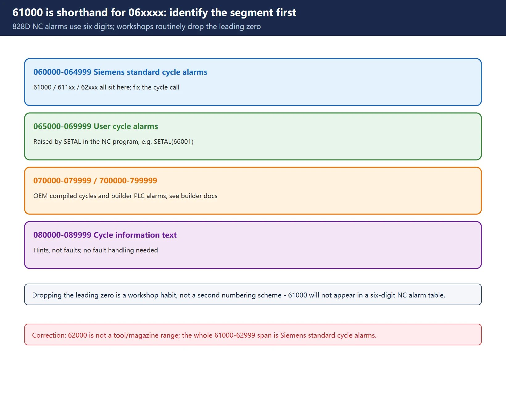
828D NC alarms are organised as six-digit numbers in the 000000–099999 band. In speech and program comments the leading zero is usually dropped, so 061000 becomes 61000 and 062321 becomes 62321. That shorthand is a workshop habit, not a separate numbering scheme — do not look up 61000 in a “six-digit NC alarm” table or treat it as a generic syntax alarm.
Once the segment is identified, ownership is clear:
- Lower 06xxxx: Siemens standard cycles, system-supplied alarm text — fix the cycle call;
- 065000–069999: user cycles raised by
SETAL— fix the cycle program; - 070000+ / 700xxx: OEM compiled cycles and builder PLC alarms — use builder documentation;
- 08xxxx: cycle information texts, hints rather than faults.
One widespread misconception deserves a correction: the 62000 range is not specifically “tools / magazine”. The whole 61000–62999 span sits inside the Siemens standard cycle-alarm range, and 62xxx contains probing/measuring cycle alarms among others. A tool-table problem can certainly *cause* a cycle alarm, but that is a cause, not a definition of the number range.
2. Where cycle alarms come from
When a cycle (CYCLE81/83, CYCLE840, milling cycles, probing cycles) is called, it validates its input parameters first. Failed validation raises an alarm and stops the interpreter. Four common sources:
- Missing or out-of-range parameters: reference plane, retract plane, depth, thread pitch, machining type VARI, spindle direction SDIR;
- Tool / offset state not satisfied: the classic
61000described below; - Missing machine or setting data: MD/SD the cycle depends on, or a channel/axis configuration mismatch;
- Missing PLC response: the cycle waits for an external acknowledgement (probe signal, clamp confirmation) and times out.
Category 4 is the minority. Check the cycle call first and the PLC last — that order removes most wasted diagnostics.
3. Alarm 61000 and reading the high-frequency codes
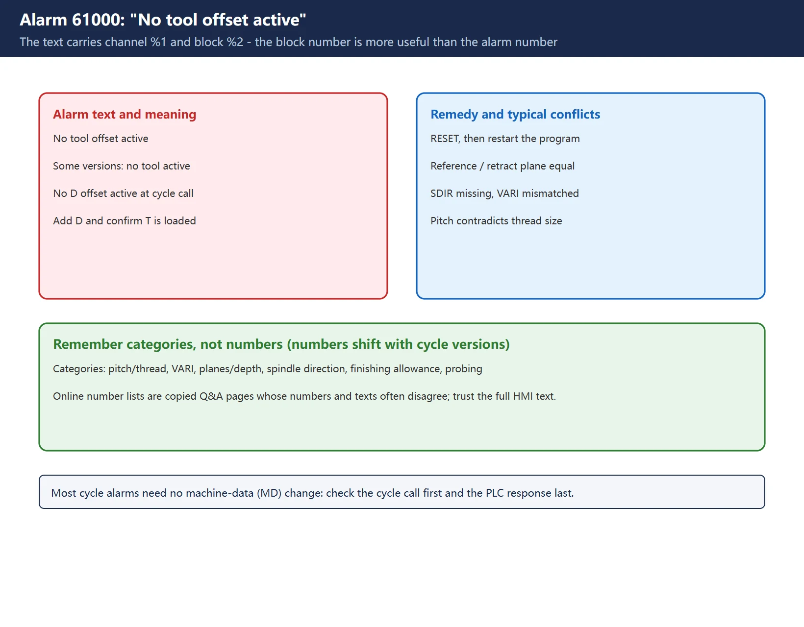
61000 is one of the codes documented in Siemens manuals: the text is “No tool offset active” (some versions show “no tool active”), meaning no tool offset was active when the cycle was called. The remedy is to program a D offset before the cycle call (and verify the T tool is loaded and the offset number is not 0), then press RESET to clear the alarm and restart the part program.
Learn to read the fixed structure of the alarm text too: it normally carries channel %1 and block %2 (sometimes a tool number %3). Block N... tells you exactly which line called the cycle — more useful than memorising the alarm number.
Other frequent cases are better remembered by category, not by number (numbers shift with cycle versions):
| Category | Typical conflict | Direction |
|---|---|---|
| Thread / pitch | Thread size and pitch contradict | Align with the drawing, change one |
| Machining type VARI | VARI code does not match other fields | Check the VARI definition |
| Reference / retract plane | Cannot be equal with incremental depth | Separate them or use absolute depth |
| Spindle direction | SDIR missing (SDR on CYCLE840) | Add the direction parameter |
| Finishing allowance | Floor allowance larger than depth infeed | Reduce allowance or raise infeed |
| Probing cycles | Probe not switching, safety margin, oversize | Measuring input, approach, TSA/TUL/TLL |
This is a category summary, not a number-to-meaning table. Numbered lists circulating online are largely copied Q&A pages whose numbers and texts often disagree. Trust the full alarm text on the HMI.
4. Pairing with the cycle parameter reference
A separate article on this site lists the CYCLE parameter fields. Use the two together like this:
Alarm -> cycle name and block number from the alarm text -> that cycle’s parameter table -> identify the field to change -> verify in single block.
If the alarm says the reference plane and retract plane cannot be equal, go to the parameter table, find those two fields and check whether the program assigned the same value — do not start editing machine data or suspecting the PLC. Most cycle alarms need no MD change at all.
5. Five-step troubleshooting order
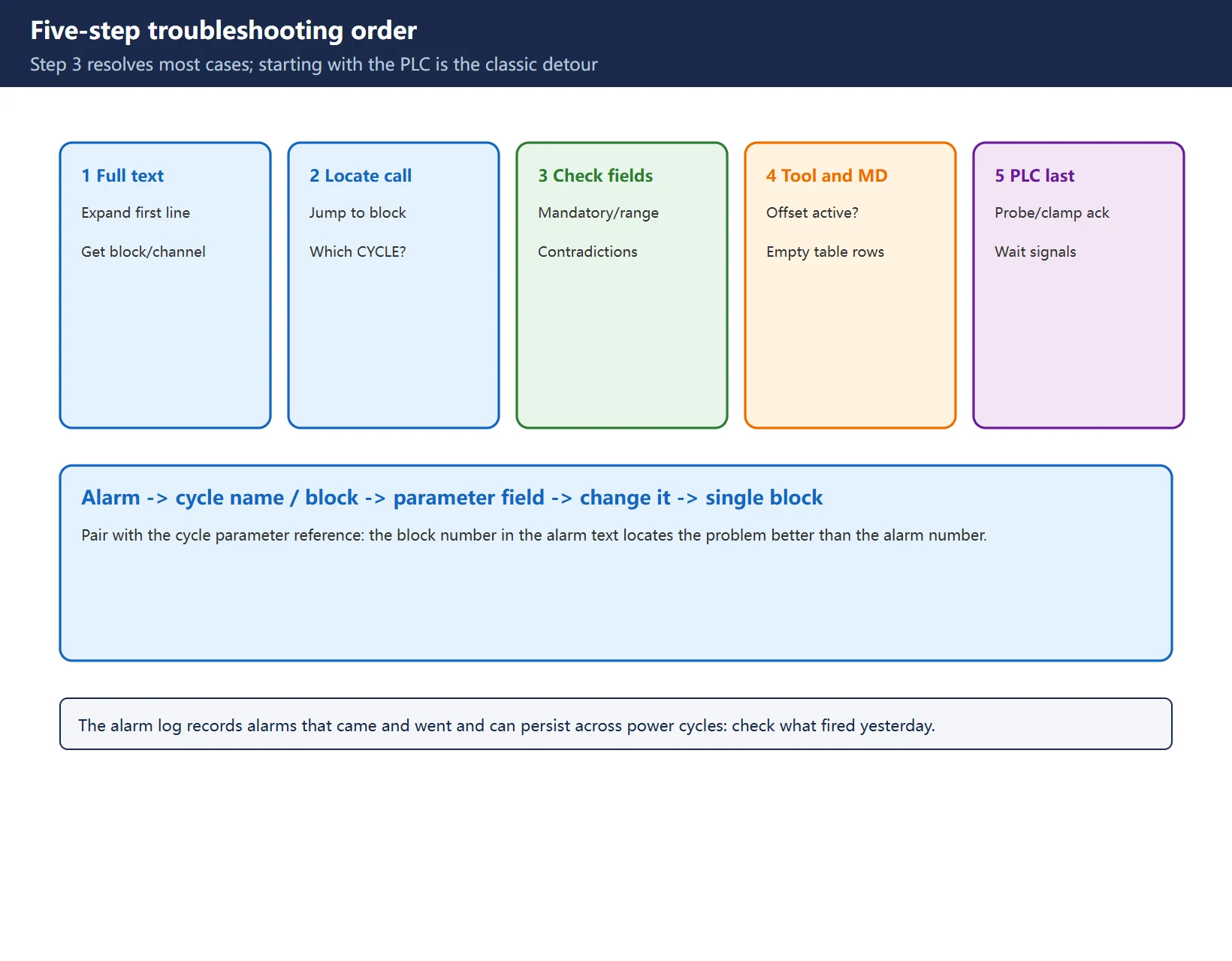
- Read the full alarm text: the HMI may show only the first line — expand it to see channel, block number and the actual values substituted into the placeholders;
- Locate the cycle call: jump to that block and confirm which cycle is invoked (
CYCLE81,CYCLE840, a probing cycle, a user cycle); - Check parameters field by field: mandatory fields, value ranges, and contradictions between fields;
- Check the tool table and machine data: is the offset active, are there empty rows or missing geometry, are the MD/SD the cycle needs configured;
- Only then check PLC responses: probe inputs, clamp acknowledgement, external wait signals.
Step 3 resolves most cases. Starting with the PLC or suspecting hardware is the classic detour on these alarms.
6. Reset and resuming
Cycle alarms occur during NC program interpretation/preparation; the typical response is interpreter stop, NC start disable for that channel, alarm display. The normal remedy is to correct the program or parameter, press RESET to clear, and restart the part program.
Do not resume from the interrupted block without confirming the machine state. A cycle call may already have changed coordinates, tool, spindle direction, coolant and modal states. Before resuming, at minimum confirm:
- Current tool and offset, spindle direction and speed;
- Axis positions and whether the work offset is still as expected;
- Whether the cycle has partly executed (for example already drilled to some depth).
The conservative route is to return to a safe start point or verify with single block plus dry run, then switch back to automatic. The exact reset class follows the response note attached to that specific alarm.
Use the alarm log: the HMI records alarms that appeared and cleared, which is exactly how you catch intermittent faults; it can be configured to persist across power cycles. Checking “what fired yesterday” beats waiting at the machine for a recurrence.
7. Four field traps
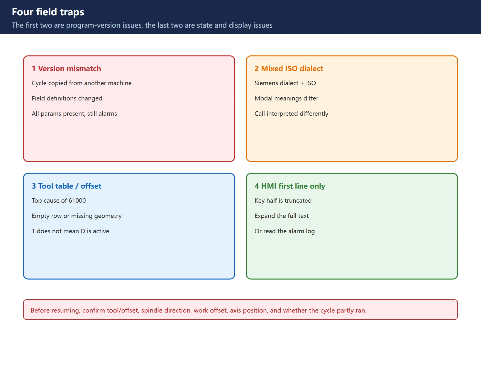
- Cycle version does not match the control version: cycles or programs copied from another machine may use field definitions that have since changed — all parameters look present, yet the alarm persists;
- Mixed ISO dialect: combining the Siemens dialect and ISO dialect in one program changes modal meanings, so the cycle call is interpreted differently;
- Empty tool-table row / inactive offset: the top cause of
61000; programming T does not mean D is active; - HMI shows only the first line: the truncated text usually omits the important half — expand it or read the alarm log.
Frequently Asked Questions
Is 828D alarm 61000 on the same numbering scheme as six-digit NC alarms?
Yes, just written differently. 828D NC alarms use six digits, and 61000 is the workshop shorthand for 061000, inside the 060000–064999 Siemens standard cycle-alarm band. It is not a separate five-digit scheme, which is why it will not appear in a generic NC program alarm table. Identify the segment first, then check the cycle call parameters.
How do I read the cycle name and block number in the alarm text?
The alarm text normally carries a channel number and a block number (sometimes a tool number). If the HMI shows only the first line, expand the full text or read it from the alarm log, then jump to that block to see which cycle was called and check its parameter fields one by one. The block number locates the problem better than the alarm number itself.
After RESET, can I continue straight from the interrupted block?
Not recommended. Clear the alarm with RESET and restart the part program after correcting the cause; before any mid-program resume, verify tool and offset, spindle direction, work offset and axis position, and whether the cycle already partly executed (for example a hole drilled halfway). Returning to a safe start point or verifying with single block plus dry run is safer. Follow the response note of the specific alarm for the exact reset class.
Last updated: 2026-11-07
Setting Data (SD) vs Machine Data (MD) on SINUMERIK 828D
SINUMERIK 828D Common Machine Data Quick Reference
SINUMERIK 840D/828D UAFEHL Alarm Explained
SINUMERIK 828D External Program / DNC
Where to go next
- FANUC Troubleshooting — the full guide library: alarms, diagnosis numbers, servo, spindle, PMC and electrical faults, organised by symptom.
- CNC Repair Tools — which instrument measures what: multimeters, clamp meters, insulation testers and oscilloscopes, with the specification that actually matters.
- Remote Technical Support — have the readings reviewed with you: alarm reverse lookup, PMC ladder analysis and servo tuning advice by call. Repair companies and integrators welcome.
Read the guide, get the right instrument, or walk the diagnosis through with someone — pick whichever you need.
The original Chinese version — same procedure, with the full field notes.

















暂无评论内容