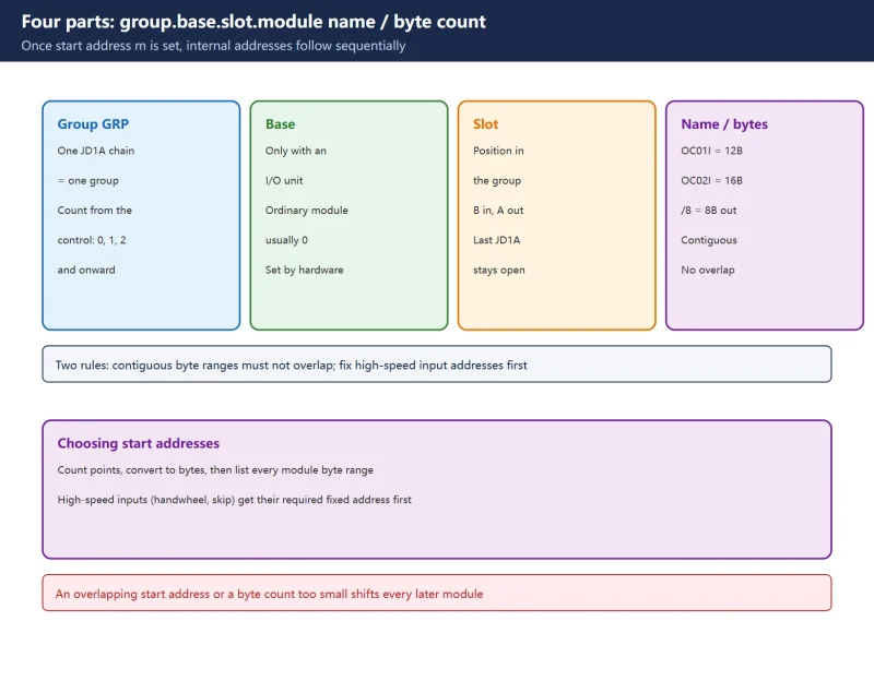



Scope and compliance: the module names and byte counts, the group/base/slot expression, the 16-byte handwheel rule, the
11933#0boundary and the write-to-ROM sequence on this page come from publicly available FANUC I/O module setup and field commissioning material, consistent with FANUC MPG Handwheel Not Working? on this site. Point counts, address limits, parameter numbers and screen names vary with the PMC model, control generation and I/O module type. This page gives assignment rules and decision order only: it reproduces no ladder manual text and provides no manual download, file mirror or archive. Every value must be checked against the local PMCDGN / PMC configuration screens and the machine-specific manual.
30-Second Triage: What Are You Solving
Table 0 Seven field scenarios and where to start
1. Reading the Four-Part Expression: Group.Base.Slot.Module/ByteCount
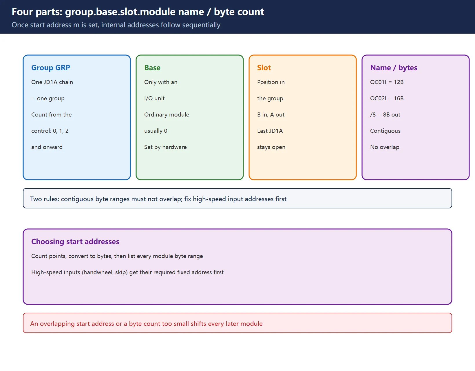
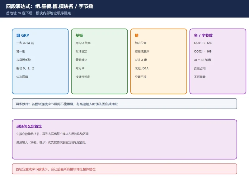
In the I/O Link “Module” screen, a module’s position and size are written in a form like 2.0.1.OC01I/12:
| Part | Meaning | How it is decided on site |
|---|---|---|
Group (GRP) | One chain of modules coming off a single JD1A port | Numbered 0, 1, 2… starting from the group closest to the control |
| Base | Base number, only needed when an I/O unit is used | Set from the hardware; often 0 for ordinary modules |
| Slot | Module position within the base / group | Follows the physical connection order |
| Module name / byte count | Module type and the bytes it occupies | e.g. OC01I = 12 input bytes, /8 = 8 output bytes |
Table 1 The four parts and how to determine them (screen wording varies by control generation)
Cable direction has a hard rule too: the cable leaves the control’s JD1A (or JD51A) and goes to the next module’s JD1B, then from that module’s JD1A to the next JD1B — “B in, A out” in field language. The last module’s JD1A stays unconnected. Group numbers follow that chain, counting from the end nearest the control.
Two rules: (1) start addresses m / n can in principle be chosen freely within the allowed range, but each module occupies contiguous bytes, so start addresses of different modules must never overlap; (2) when high-speed inputs are present (handwheel, skip signal), fix the start address to satisfy the high-speed signal first, then arrange the remaining modules to avoid conflicts.
2. Module Names and Byte Counts
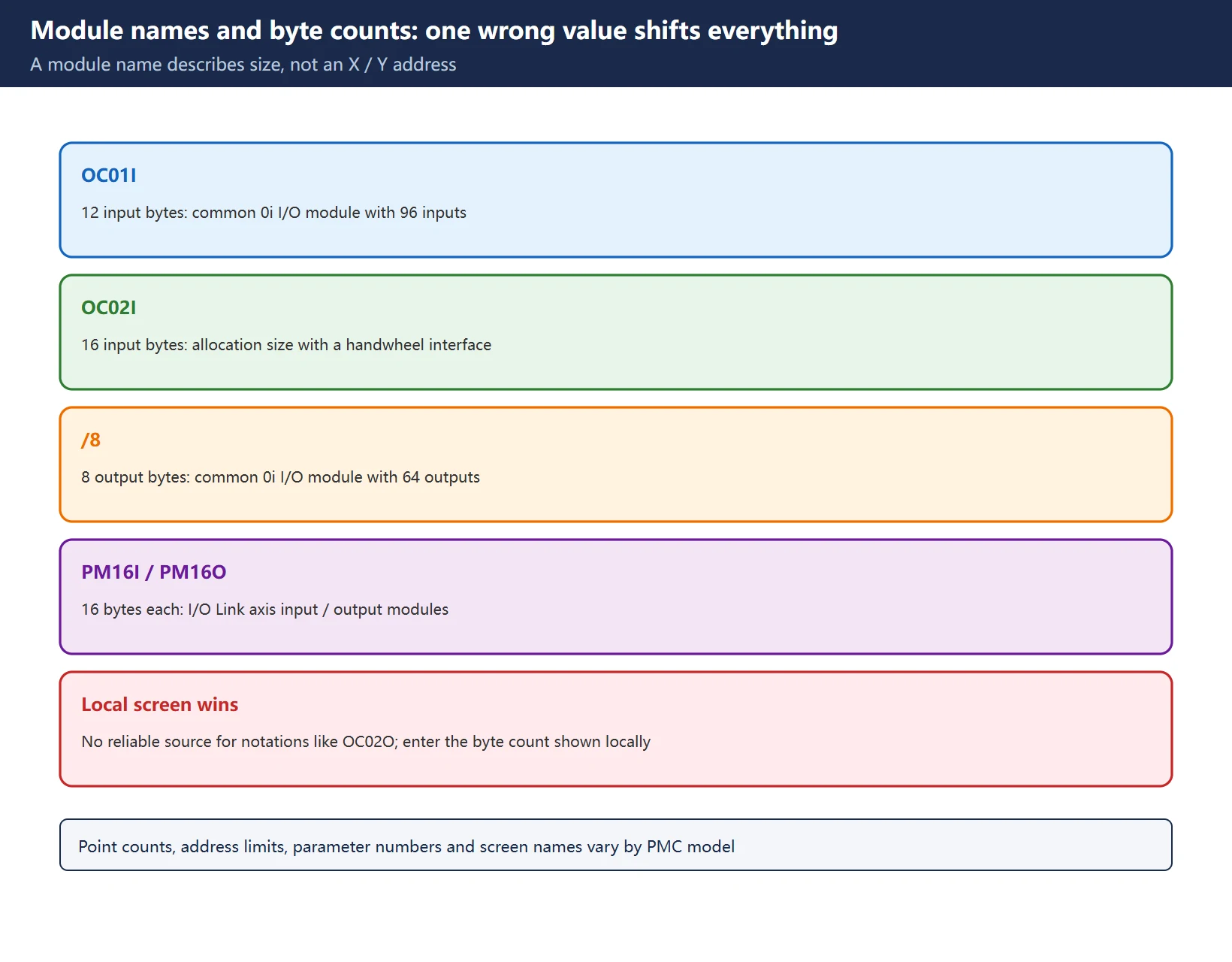
The digits and suffixes in a module name map directly to the bytes it occupies. A wrong byte count shifts the addresses of every module after it:
| Notation | Meaning | Note |
|---|---|---|
OC01I | 12 input bytes | Common 0i I/O module with 96 inputs = 12 bytes |
OC02I | 16 input bytes | Allocation size with a handwheel interface |
/8 | 8 output bytes | Common 0i I/O module with 64 outputs |
PM16I / PM16O | 16 bytes each | I/O Link axis input / output modules |
Table 2 Common module names and occupied bytes (**model dependent; use the local module screen**)
Do not treat a module name as another address system: notations like OC02I describe module type and byte count, not an X/Y address. Some online lists present OC02O and similar strings as official output module names; no reliable source was found for that in this check, so this page does not use it. Enter the output-side byte count as shown on the local screen (for example /8). If the local module names differ, always defer to the local screen.
3. The 16-Byte Handwheel Rule
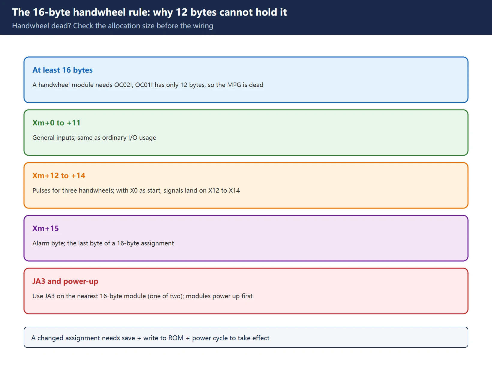
This is the single most consequential rule in I/O Link assignment:
- A module carrying a handwheel must be assigned at least 16 bytes (
OC02I).OC01Ihas only 12 bytes, which cannot hold the handwheel pulse signals, so the handwheel stays dead. - With a 16-byte assignment, the internal layout is:
Xm+0toXm+11general inputs,Xm+12toXm+14pulse inputs for three handwheels,Xm+15alarm byte. If the module starts atX0, handwheel signals land onX12toX14. - Connect the handwheel to the
JA3connector on the 16-byte module nearest the control. TheJA3on the control-side I/O board and theJA3behind the operator panel are alternatives: only the assigned one is active. - A changed assignment requires save + power cycle to take effect, and the modules must power up before the control, otherwise the control does not detect them at startup.
Table 3 Four handwheel-related assignment constraints
When a connected handwheel does nothing, walk back along this chain: is the module assigned as OC02I → which JA3 is it on → does Xm+12 toggle → is the handwheel enable signal active in the PMC. The full signal chain is in FANUC MPG Handwheel Not Working?; station dropout and whole-address drift are covered in How to Troubleshoot I/O Link & PROFIBUS Station Dropout.
4. Two Generations: I/O Link vs I/O Link i and 11933#0
The screen names and parameters differ between the two generations; mixing them up takes you to the wrong screen:
| Comparison | I/O Link | I/O Link i |
|---|---|---|
| Control generation | 0i-D and earlier | Progressively from 0i-F onward |
Parameter 11933#0 | Does not exist | Set 1 when channel 1 uses I/O Link i, 0 otherwise |
| Assignment screen | SYSTEM → PMC config → Module | SYSTEM → PMC config → I/O Link i (edit / zoom / assignment selection) |
| Position notation | group.base.slot.name/bytes | Channel, GRP, slot, input start address and byte count |
| Points and speed | 1024 inputs / 1024 outputs per channel | 2048 / 2048 per channel; sequence program about 1.5x faster |
| Groups | Configured per channel | Up to 24 groups per channel (0 to 23) |
Table 4 Six differences between the two generations (parameter bits and group limits: use the local manual)
Two more field facts: I/O Link i requires dedicated I/O Link i modules, so confirm this when ordering; and dual-channel safety signals can share one I/O chain with ordinary modules on I/O Link i, using a single cable. Cable length is limited too (commonly around 15 m for copper, up to roughly 200 m via optical link adapters) — check the machine-specific manual for exact figures rather than relying on rule-of-thumb lengths.
5. Four Assignment Patterns, Not a Fixed Address Table
These are assignment patterns for four common scenarios, not an address table to copy. Point counts, module types and start addresses differ on every machine and must be calculated from the actual hardware:
| Scenario | Assignment pattern | Easiest mistake |
|---|---|---|
| Single group of 0i I/O modules (96 in / 64 out) | One 12-byte input start address, one 8-byte output start address | Treating 96 points as 96 bytes |
| Handwheel required | Assign that module 16 bytes (OC02I), connect to the nearest module's JA3 | Keeping 12 bytes, so the handwheel stays dead |
| Adding one more I/O unit group | Increment the group number along the chain; keep the new start address outside occupied byte ranges | Overlapping start addresses, shifting everything downstream |
| I/O Link axis / safety I/O | Use PM16I / PM16O or dedicated I/O Link i modules; confirm channel and group | Mixing module names from the two generations |
Table 5 Four assignment patterns (patterns only, not a fixed address table)
To trace an X point back to a terminal, or to reverse-look-up an alarm into an I/O address, see FANUC PMC External Alarm Reverse Lookup. PMC screen and signal-status basics are in Fanuc 0i-MD PMC Diagnostic Screens.
6. Applying the Assignment: Five-Step Verification
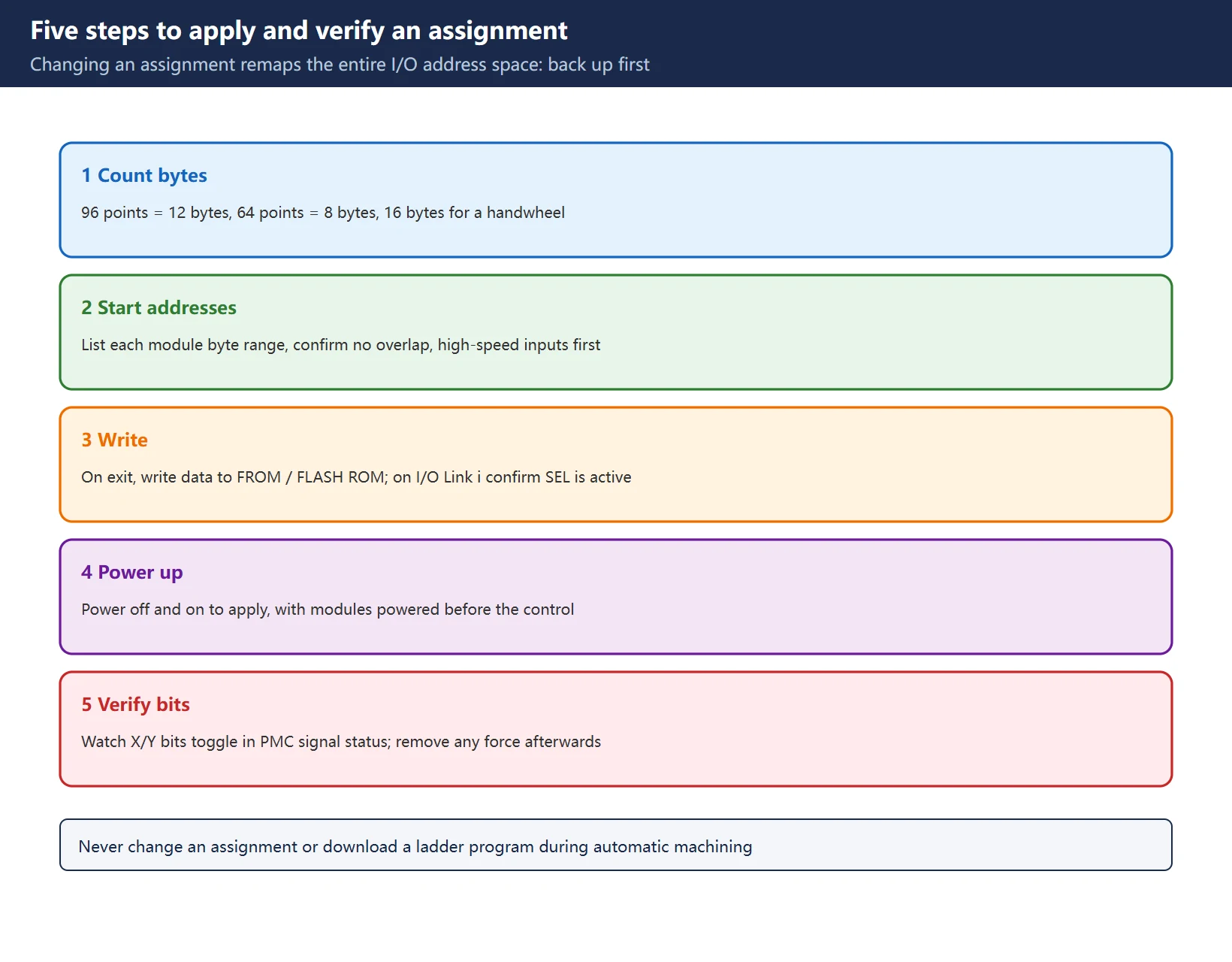
- Count bytes: total the input / output points per module and convert to bytes (96 points = 12 bytes, 64 points = 8 bytes, 16 bytes for a handwheel).
- Choose start addresses: list the contiguous byte range each module occupies and confirm there is no overlap; fix high-speed input addresses first.
- Write: after editing in the assignment screen, exit and confirm writing the data to FROM / FLASH ROM (answer “Yes”); on I/O Link i also confirm that
SELis active under assignment selection. - Power up: power off and on again for the change to take effect, with modules powered before the control.
- Verify bit by bit: watch the corresponding X/Y bits toggle in the PMC signal status screen; where needed, use How to Use FANUC PMC Force Output for reverse verification, and always remove the force afterwards.
Table 6 Five assignment faults and where to look first
Changing an assignment remaps the entire I/O address space. Take a recoverable PMC and parameter backup first (see How to Export / Print FANUC Parameter Tables), and never change an assignment or download a ladder program during automatic machining.
7. Official Search Keys and Compliance Boundary
| Search key | Verifiable wording | Use |
|---|---|---|
| Screen path | SYSTEM → PMC config → Module / I/O Link i | Find the correct assignment screen |
| Module names | OC01I, OC02I, PM16I, PM16O | Check byte counts by module name |
| Expression | group.base.slot.name/bytes | Read the position column in the module list |
| Parameter | 11933#0 | Decide whether this is I/O Link i |
| Manual type | PMC Ladder Language manual / I/O module connection manual | Point limits and address ranges by model |
Table 7 Five official search keys
Manual text and full module address tables are copyright protected. This page reproduces no manual text and provides no download link, file mirror or archive; address ranges, group limits and parameter bit definitions must be checked against the local PMC model and the machine-specific manual. For matching PMC addresses to wire numbers on drawings, see How to Read a CNC Machine Electrical Schematic.
8. Related Guides on This Site
Table 8 Related guides referenced by this page
Frequently Asked Questions
What does “2.0.1.OC01I/12” mean in FANUC I/O Link address assignment?
It is the four-part position and size description: 2 is the group number (counting 0, 1, 2 along the chain from the group nearest the control), 0 is the base number (only set when an I/O unit is used), 1 is the slot, OC01I is the module name, and /12 means 12 input bytes (the common 96-input module). The output side needs its own start address with its byte count, for example /8. Once the start address m is set, that module’s internal addresses follow sequentially, so the critical point is that contiguous byte ranges must not overlap. I/O Link i uses different screen wording — channel, GRP, slot, input start address and byte count — so always defer to the local screen.
Can address assignment cause a connected handwheel to do nothing?
Yes, and it is one of the most common causes. The module carrying a handwheel must be assigned at least 16 bytes (OC02I); the 12 bytes of OC01I cannot hold the handwheel pulses, so the handwheel stays dead. With 16 bytes, Xm+0 to Xm+11 are general inputs, Xm+12 to Xm+14 are pulses for three handwheels and Xm+15 is the alarm byte. The handwheel must also be connected to the JA3 on the 16-byte module nearest the control, with the control-side I/O board JA3 and the panel JA3 being alternatives. After changing the assignment you must save, write to ROM, power cycle, and power the modules before the control. The full bit-by-bit verification chain is in the handwheel guide on this site.
Parameter 11933 cannot be found. Is the control faulty?
No. I/O Link and I/O Link i are two generations: 11933#0 belongs to I/O Link i (set 1 when channel 1 uses it), while 0i-D and earlier controls use I/O Link and simply do not have that parameter, with the assignment screen at SYSTEM → PMC config → Module rather than I/O Link i. Confirm the control generation and PMC model in the system configuration first, then pick the right screen. I/O Link i also needs dedicated I/O modules, so never mix module names from the two generations; point limits, group counts and parameter bit definitions always come from the machine-specific manual.
Last updated: 2026-11-11
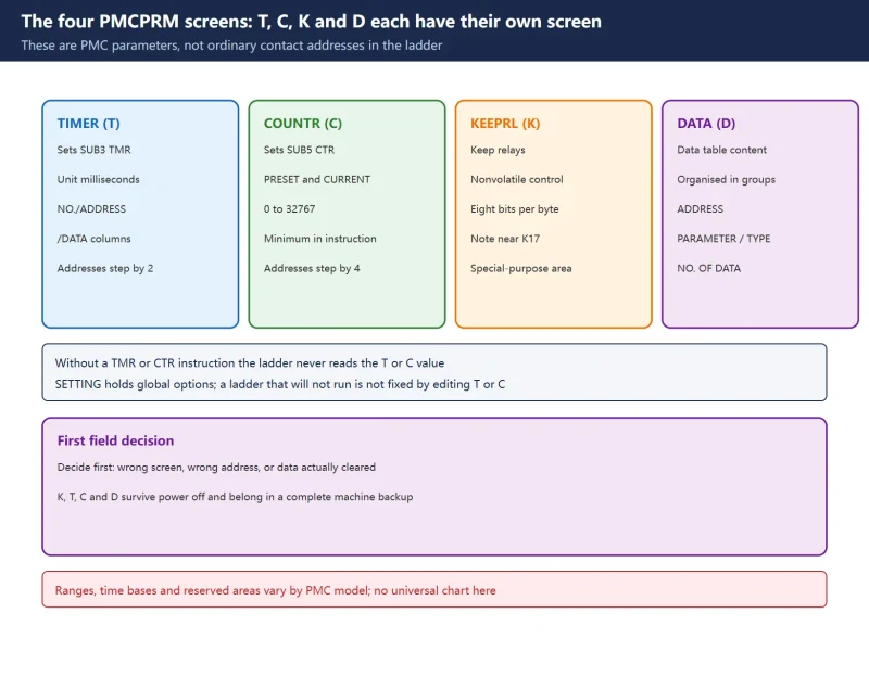
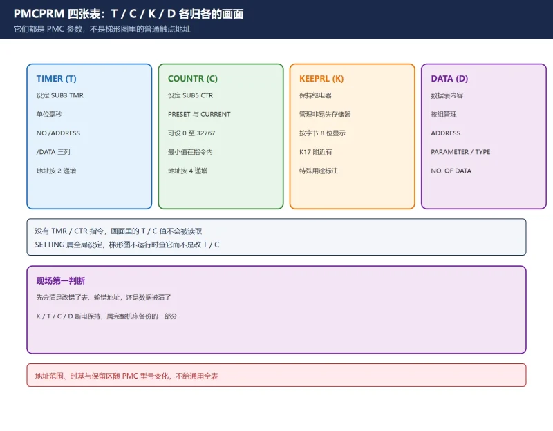
Beyond I/O Link assignment: the four PMCPRM parameter screens
Where to go next
- FANUC Troubleshooting — the full guide library: alarms, diagnosis numbers, servo, spindle, PMC and electrical faults, organised by symptom.
- CNC Repair Tools — which instrument measures what: multimeters, clamp meters, insulation testers and oscilloscopes, with the specification that actually matters.
- Remote Technical Support — have the readings reviewed with you: alarm reverse lookup, PMC ladder analysis and servo tuning advice by call. Repair companies and integrators welcome.
Read the guide, get the right instrument, or walk the diagnosis through with someone — pick whichever you need.
The original Chinese version — same procedure, with the full field notes.















暂无评论内容