


Scope and compliance: the configuration sequence and parameters verified on this page (the X1/X2 network split, device name and IP address,
MD12986, TIA Portal module insertion order,MD11241and the SDB version gate for byte extension) come from Siemens CNC4YOU technical documents 1390 / 1391 and the SINUMERIK 828D Commissioning Manual. Manual text, SDB files and software update packages are copyright protected. This page explains configuration order and decision criteria only: it reproduces no manual text and provides no SDB file download, software package, file mirror or archive. Software versions, order numbers, byte counts and addresses must be checked against the machine-specific manual and the actual configuration.
30-Second Triage: Which Route Are You Configuring
Table 0 Seven field scenarios and where to start
1. Two Different Layers: Cyclic I/O Mapping vs One-Sided S7 Connection
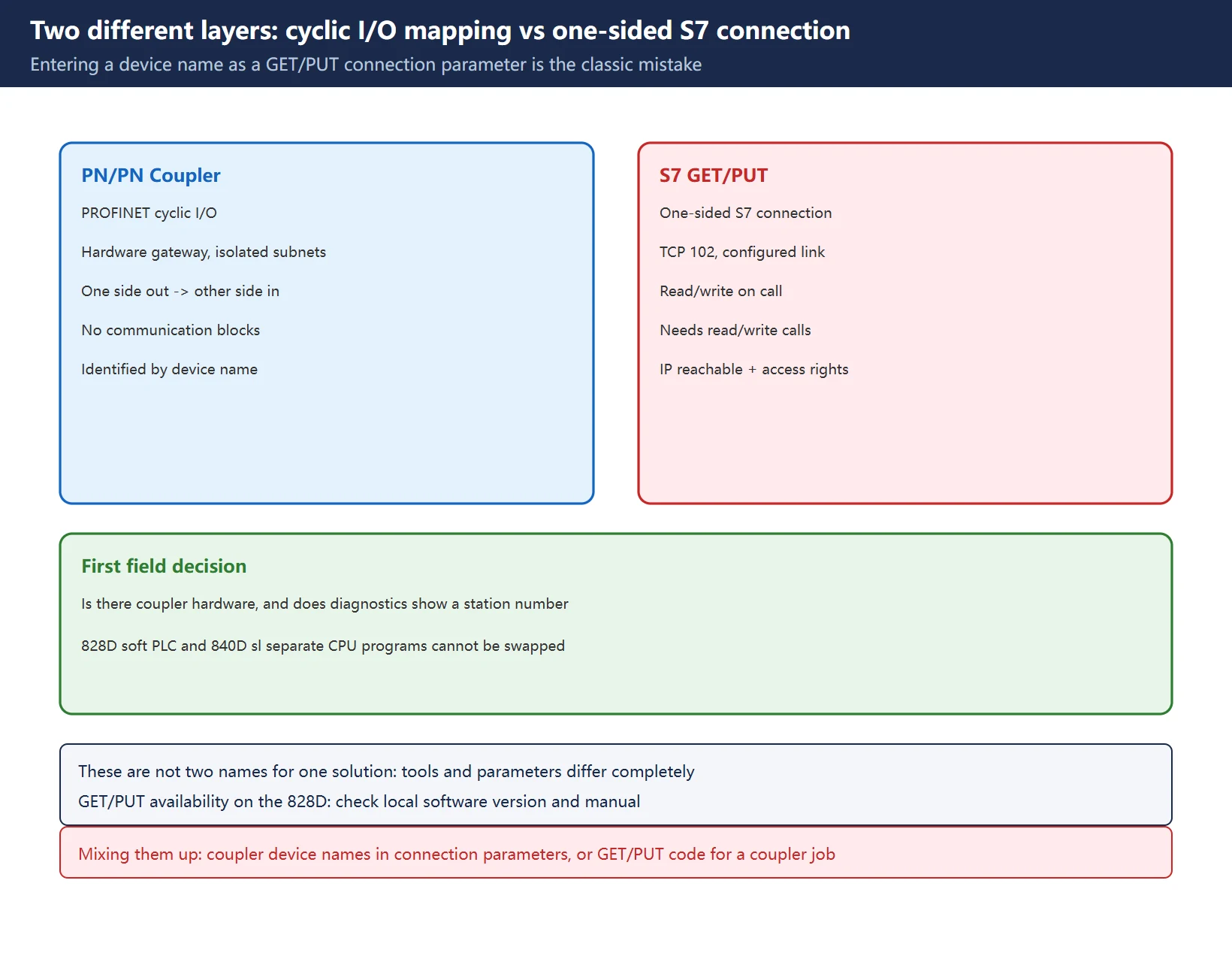
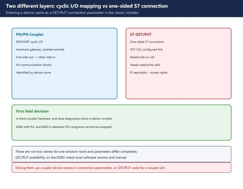
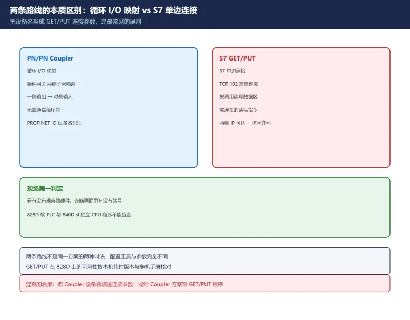
A PN/PN Coupler is a gateway. Its two RJ45 ports belong to separate, isolated PROFINET subnets; data written to an output address on one side appears automatically at the mapped input address on the other. Exchange happens at the cyclic I/O layer, so it uses neither GET / PUT nor BSEND / BRECV and needs no communication program blocks.
S7 GET/PUT is different: a one-sided S7 connection over TCP 102, where the initiating PLC calls read/write instructions against the partner’s data area. It needs connection resources, PUT/GET access permission on the partner CPU, and IP reachability. There is no coupler hardware and the exchange is acyclic, happening only when called.
| Comparison | PN/PN Coupler | S7 GET/PUT one-sided connection |
|---|---|---|
| Exchange layer | PROFINET cyclic I/O mapping | S7 protocol (acyclic, on call) |
| Coupler hardware required | Yes | No |
| Communication blocks required | No | Yes, plus a configured connection |
| Port / protocol | PROFINET IO, identified by device name | TCP 102, IP connection |
| Main tools | SIMATIC Manager (828D) + TIA Portal (S7) | TIA Portal / STEP 7 connection configuration |
| Field indicator | Coupler station visible in diagnostics | Connection resources and partner access permission |
Table 1 Six comparison points (architecture varies by control and software version; verify on site)
The classic mistake: treating “828D to S7-1200 communication” as a single configuration sheet, then entering the coupler’s device name and IP as GET/PUT connection parameters, or conversely writing GET/PUT code for a coupler solution. Neither leads to the right screen. Also, the 828D has a soft PLC (S7-200 family) while the 840D sl has a separate CPU (S7-300 family); programs cannot be swapped between them. GET/PUT availability and call syntax on an 828D vary considerably by control type and software version, so this page gives no universal answer: check the machine-specific manual. For a different approach to CNC-to-external-PLC links, see SINUMERIK PLC Basic Program: FB1, FB2 and OB100.
2. Hardware and Network Split: X1 to the 828D, X2 to the S7-1200
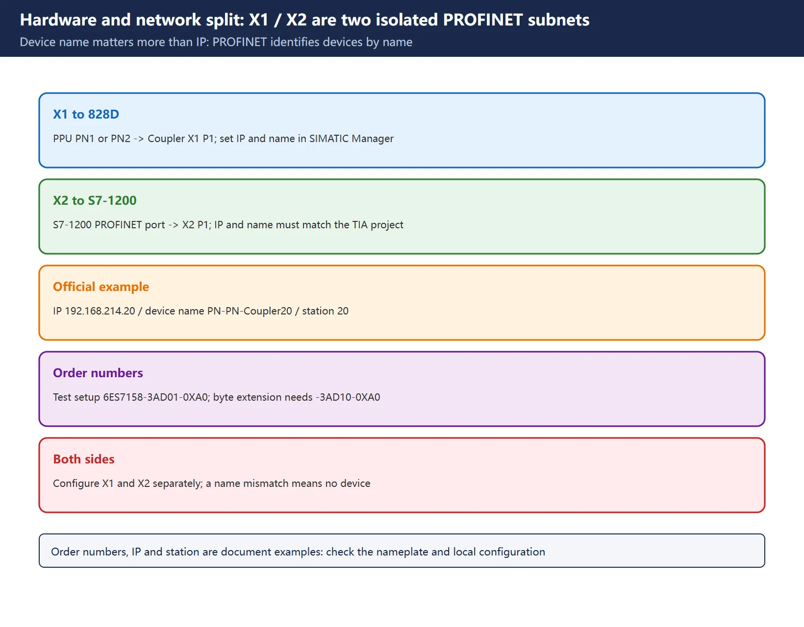
In the official example, PPU port PN1 or PN2 connects to X1 P1 on the coupler, and the S7-1200 PROFINET port connects to X2 P1. X1 and X2 are two isolated subnets that must be configured separately, and the device name and IP address set on each side must match the hardware configuration in the corresponding project.
| Side | Connected to | Tool | Official example values |
|---|---|---|---|
| X1 (828D side) | 828D PPU PN1 / PN2 | SIMATIC Manager, PLC → Edit Ethernet Node | IP 192.168.214.20, device name PN-PN-Coupler20 |
| X2 (S7-1200 side) | S7-1200 PROFINET port | TIA Portal hardware configuration | IP and device name must match the TIA project |
| Diagnostics | 828D Diagnostics → TCP/IP bus | Select PROFINET PN1/PN2 | Check station 20 |
Table 2 Configuration responsibility per side and official example values (examples only; use the actual configuration)
PROFINET identifies devices by device name, not by IP alone: the official procedure explicitly requires entering the device name and activating the configuration. For order numbers, the test setup used 6ES7158-3AD01-0XA0; byte extension requires the newer 6ES7158-3AD10-0XA0 (CNC4YOU 1391). These are example hardware from specific documents: check the actual nameplate, since machine configurations and procurement batches differ.
3. 828D-Side Configuration: MD12986 and NCK Restart
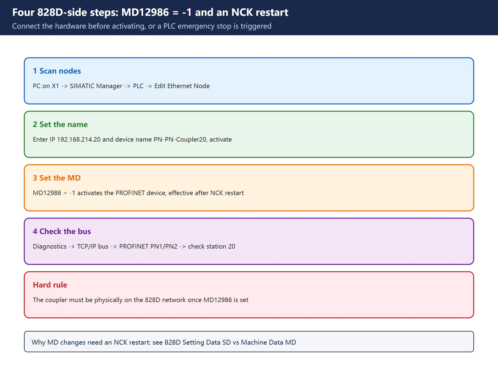
The official 828D-side sequence has four steps:
- Connect a PC to the X1 network, set the PG/PC interface in SIMATIC Manager, use PLC → Edit Ethernet Node to scan for network devices and select the PN/PN Coupler.
- In the Edit Ethernet nodes dialog, enter IP
192.168.214.20and device namePN-PN-Coupler20, then activate the configuration. - On the 828D, set
MD12986 = -1to activate the PROFINET device. It takes effect after an NCK restart. - After the restart, go to Diagnostics → TCP/IP bus to check whether the coupler is configured correctly.
Connect the hardware before activating: the official text states that once
MD12986 = -1is set, the PN/PN Coupler must already be physically connected to the 828D PROFINET network, otherwise a PLC emergency stop alarm is triggered. This is the most common field trap. The parameter is not wrong; the order is.
Table 3 Four 828D-side steps and their activation conditions
| Step | Action | Activation / check |
|---|---|---|
| 1 | Scan and select the coupler | Device appears in the node list |
| 2 | Set IP and device name, activate | Device name matches the project |
| 3 | Set MD12986 = -1 | Effective after NCK restart |
| 4 | Diagnostics → TCP/IP bus | Check station 20 |
For why machine data changes need an NCK restart, and how MD and SD differ in activation behaviour, see 828D Setting Data SD vs Machine Data MD.
4. S7-1200/1500 Side: TIA Portal Module Order Cannot Be Reversed
On the TIA side: create a project and add the device (mind the hardware version) → insert 6ES7158-3AD01-0XA0 and establish the network connection → configure the transfer areas in the device view → set the X2 port IP and device name the same way as X1 (they must match the TIA hardware configuration).
The official example explicitly flags the order: in the coupler device view, insert the 16-byte output module first, then the 16-byte input module; this order must not be reversed. The exchange direction is “output on one side → input on the other”, so the module configurations on both sides must correspond.
Table 4 Four TIA-side items and the ordering constraint
5. Byte Extension: MD11241 and the SDB Version Gate
If 16 bytes are not enough, Siemens documents a separate byte extension path (CNC4YOU 1391) with considerably higher prerequisites than a single parameter change:
| Prerequisite | Official requirement |
|---|---|
| 828D software | SW V4.7 SP4 HF1 or later supports byte extension |
| SDB file | Version V04.07.04.01 or later, internal version 99.10.03.08 |
| Coupler model | Newer 6ES7158-3AD10-0XA0 required |
| Installation | Startup menu → Install software update/backup → USB drive → select SDB → INPUT → restart |
| Success check | Diagnostics → Version → OEM applications shows SDB40 / SDB60 / SDB80 |
| Parameter | MD11241 = 2: subslots 10 → 18, usable bytes 16 → 112 |
Table 5 Six byte-extension prerequisites and checks (version dependent; use the local manual)
Two ways to end up with a control that will not start: (1) setting MD11241 to a non-zero value and restarting before the SDB file is installed causes communication with the NC to fail and the system not to boot; recovering requires a Factory setting; (2) during Factory setting, answering YES to “delete manufacturer files” deletes the SDB files as well. YES is acceptable for the initial power-up clear, but NO is recommended for a later clear after commissioning.
Always take a full backup before a clear. 828D Cycle Alarms 61000 / 62000 covers a neighbouring alarm family; for alarm-number formatting across brands see CNC Alarm Number Formats by Brand.
6. Five-Step Commissioning Check
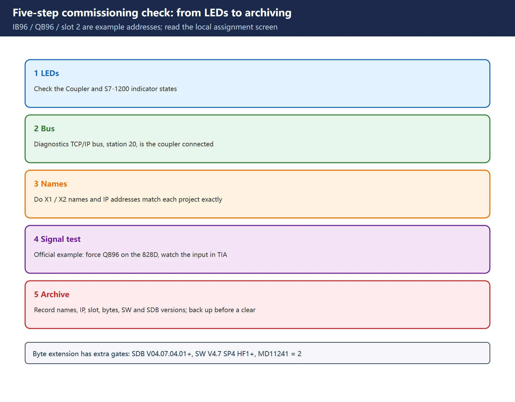
- LEDs: check the PN/PN Coupler and S7-1200 indicator states first.
- Bus diagnostics: 828D Diagnostics → TCP/IP bus → select PROFINET PN1/PN2 → check whether station 20 is connected.
- Names: confirm the device names and IP addresses on X1 and X2 match each project exactly (PROFINET identifies by device name).
- Signal test: the official example forces
QB96on the 828D and monitors the input in TIA Portal.IB96/QB96and slot 2 are addresses from that example configuration: the actual start address must be read from the local address-assignment screen, not copied. - Archive: record the final device names, IP addresses, slot, byte counts, software version and SDB version in the machine file, and back up before any clear or hardware swap.
Table 6 Four commissioning faults and where to look first
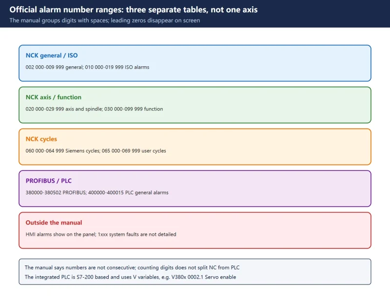
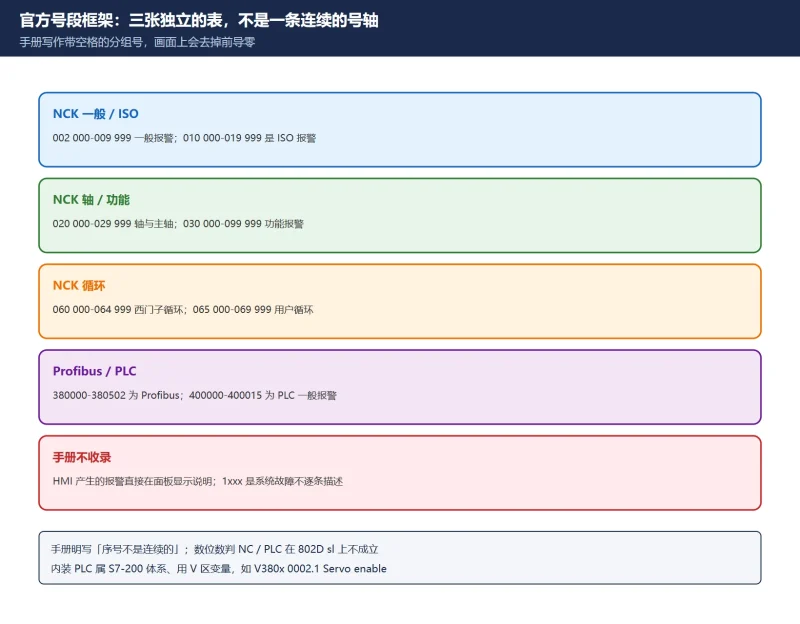
For locating communication alarms by number range, see SINUMERIK 840D sl Alarm List: NCK, Cycle, HMI, PLC. This page covers configuration and commissioning, not per-number alarm text.
7. Official Search Keys and Compliance Boundary
| Search key | Verifiable wording | Use |
|---|---|---|
| Document numbers | CNC4YOU 1390 (base configuration), 1391 (byte extension) | Locate the original on Siemens Industry Support |
| Manual name | SINUMERIK 828D / 828D BASIC Commissioning Manual | PROFINET configuration and machine data |
| Parameter search | MD12986, MD11241 | Full-text search by parameter number, not page number |
| Version keys | SW04.07+SP2+HF01, V4.7 SP4 HF1, SDB V04.07.04.01 | Decide whether the local control supports extension |
| Order numbers | 6ES7158-3AD01-0XA0 / 6ES7158-3AD10-0XA0 | Check the installed hardware and extension capability |
Table 7 Five official search keys
Manual text, SDB files and software update packages are copyright protected. This page reproduces no manual text and provides no download link, file mirror or archive. Use the official support channels with the keys above, and always defer to the local software version and the machine-specific manual. For how to navigate an official diagnostics manual by chapter, see SINUMERIK 840D sl Alarm Code Quick Reference.
8. Related Guides on This Site
Table 8 Related guides referenced by this page
Frequently Asked Questions
Should an 828D to S7-1200 link use a PN/PN Coupler or GET/PUT?
Start with the hardware and the exchange requirement. If you need stable I/O signal exchange between two isolated PROFINET subnets without consuming PLC connection resources, use PN/PN Coupler cyclic I/O mapping, which needs no GET / PUT communication blocks. Reading and writing a partner data area on call, without coupler hardware, belongs to the one-sided S7 connection route. They are not two names for one solution and their tools and parameters differ completely. The 828D uses a soft PLC, architecturally different from the separate CPU in an 840D sl, so GET/PUT availability must be checked against the local software version and the machine-specific manual. This page gives no universal answer.
Why does the control raise a PLC emergency stop after setting MD12986 = -1?
Siemens states that once MD12986 = -1 activates the PROFINET device, the PN/PN Coupler must already be physically connected to the 828D PROFINET network, otherwise a PLC emergency stop alarm results. Check the X1 cable, coupler power supply and whether the device is online, then inspect station 20 under Diagnostics → TCP/IP bus. Restart the NCK only after the hardware is confirmed online. If the station is missing or the device name differs, go back to checking device names and IP addresses on both sides.
The 828D will not start after setting MD11241 to 2. What now?
Byte extension has prerequisites: 828D SW V4.7 SP4 HF1 or later, an SDB file at V04.07.04.01 or later, and the newer coupler 6ES7158-3AD10-0XA0. Siemens notes that setting MD11241 to a non-zero value and restarting before installing the SDB file breaks communication with the NC and prevents startup; recovery requires a Factory setting. After recovery, redo the sequence as “install SDB → confirm SDB40/60/80 under OEM applications → then change the parameter”. Remember that answering YES to “delete manufacturer files” during Factory setting also removes the SDB files. Always take a full backup before a clear.
Last updated: 2026-11-11
Where to go next
- FANUC Troubleshooting — the full guide library: alarms, diagnosis numbers, servo, spindle, PMC and electrical faults, organised by symptom.
- CNC Repair Tools — which instrument measures what: multimeters, clamp meters, insulation testers and oscilloscopes, with the specification that actually matters.
- Remote Technical Support — have the readings reviewed with you: alarm reverse lookup, PMC ladder analysis and servo tuning advice by call. Repair companies and integrators welcome.
Read the guide, get the right instrument, or walk the diagnosis through with someone — pick whichever you need.
The original Chinese version — same procedure, with the full field notes.




















暂无评论内容