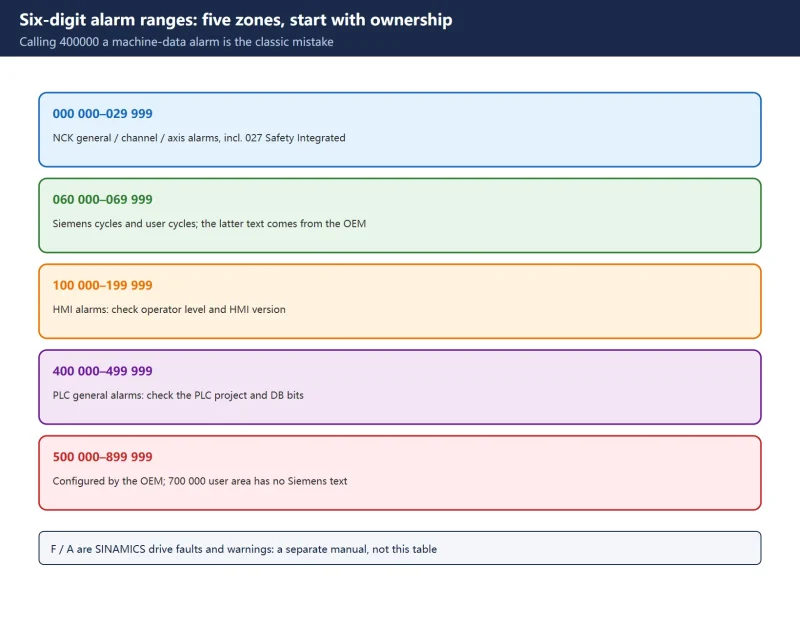



🚨 Scope and compliance: number ranges and Reaction terms come from the public chapters of Siemens’ official “840D sl / SINAMICS S120 Alarms Diagnostics Manual” (SIOS entry IDs
109806981,109748391,109752346). The version-to-page comparison was checked in our 840D sl diagnostics manual guide. The manual text is copyright protected: this page explains how to locate an alarm by range, how to read the Reaction block and which manual to open. It reproduces no per-number alarm text and offers no manual download link, file mirror or archive. Alarm text, reactions and page numbers vary with the machine builder’s configuration and the software version, so always use the manual shipped with your machine and search by the full alarm number.
30-Second Triage: Find the Section by Alarm Number
Table 0 Six field needs and their first stop
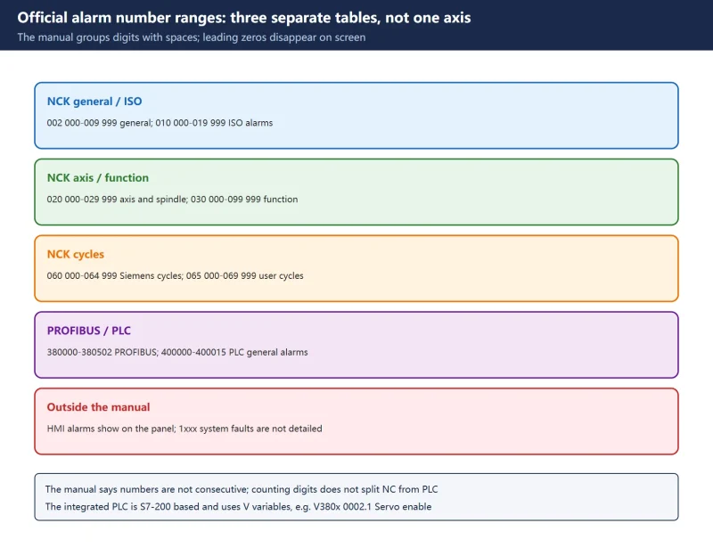
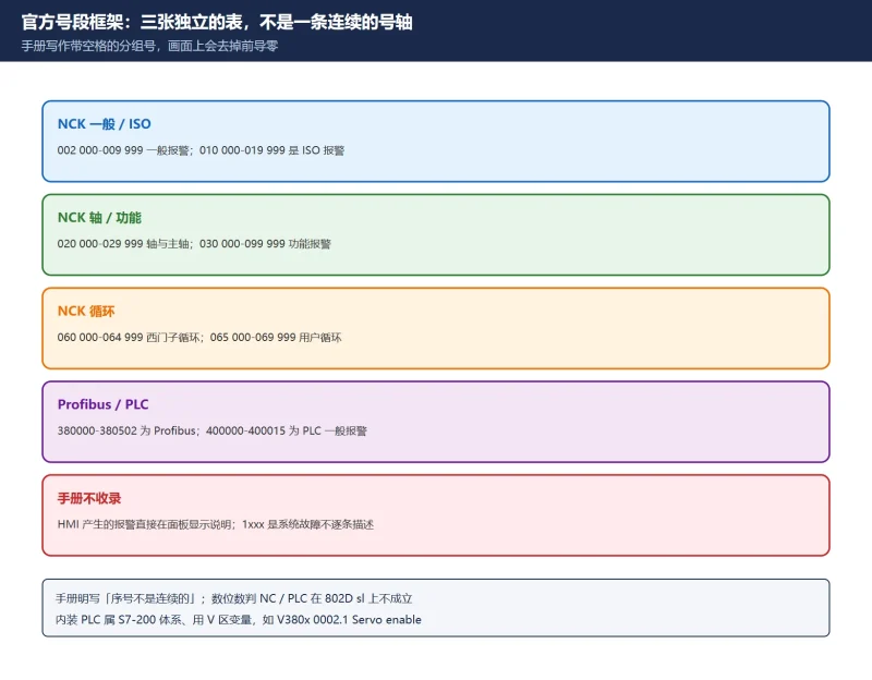
Number Ranges: How the Six-Digit Code Is Divided
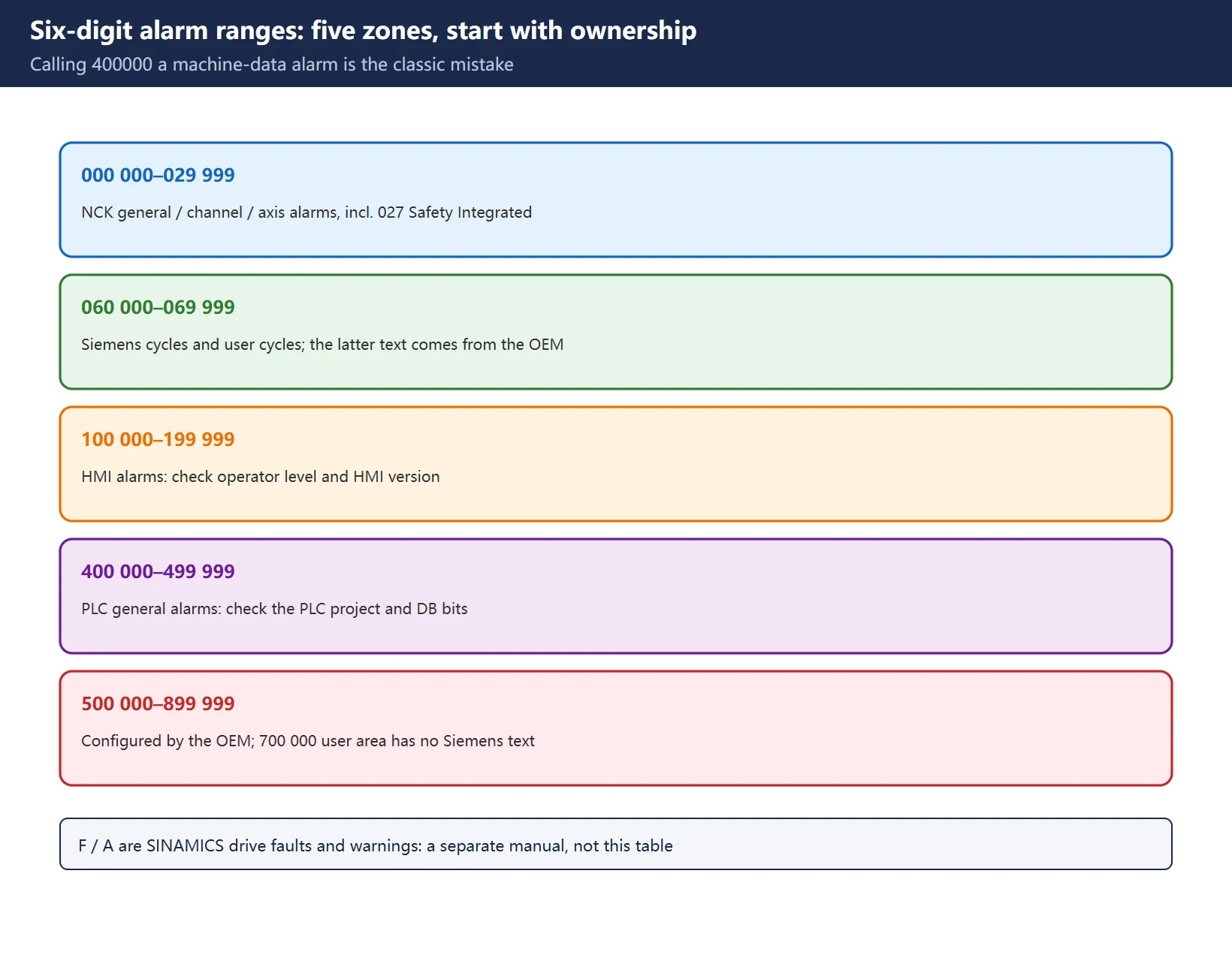
Write the number in full. A six-digit alarm must not be shortened to 4xxxx, and 400 000-499 999 is not a “machine data alarm” range: it is the general PLC alarm range. The range decides which manual to open and which team to call.
| Range | Family | Who supplies the text | First field action |
|---|---|---|---|
000 000-009 999 | NCK general alarms | Siemens | Open the NCK alarm chapter |
010 000-019 999 | Channel alarms | Siemens | Identify the channel and program block |
020 000-029 999 | Axis / spindle alarms | Siemens | Record axis number and follow-up state |
027 000-027 999 | Safety Integrated (nested inside the 020 range) | Siemens | Treat as a safety alarm; re-confirm after changes |
060 000-064 999 | Siemens cycle alarms | Siemens | Check the cycle number and call parameters |
065 000-069 999 | User cycle alarms | Machine builder / user | Inspect the user cycle project |
100 000-199 999 | HMI alarms | Siemens | Check the HMI and operator level |
400 000-499 999 | General PLC alarms | Siemens + machine builder | Check the PLC project and DB bits |
500 000-899 999 | Configured and described by the machine builder | Machine builder | Use the builder's machine documentation |
700 000-799 999 | User area, no Siemens alarm text | Machine builder | Only the local PLC project can explain it |
F... / A... | SINAMICS drive faults / warnings | Siemens drive manual | Not part of the six-digit table |
Table 1 Six-digit 840D sl alarm ranges (official manual scope)
Our 840D sl alarm list explained is the narrative companion to this map; for cycle alarms 61000 / 62000 see 828D cycle alarms.
System Responses: Official Reaction Terms
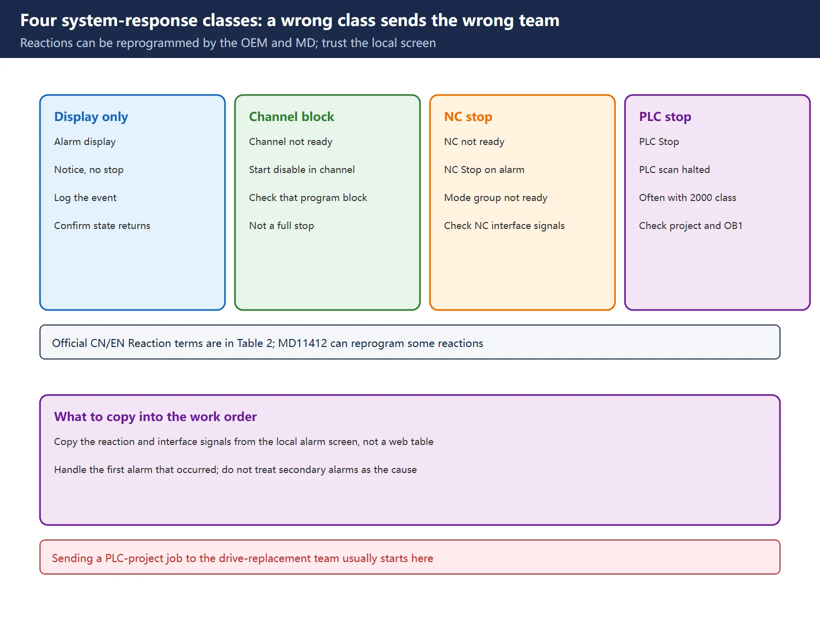
The same alarm number can produce a different Reaction on a different machine: the official manual lets machine data such as MD11412 $MN_ALARM_REACTION_CHAN_NOREADY reprogram some alarm reactions, and builders change defaults too. So a fault report should quote the Reaction block from the local alarm screen, not a table from the web.
| Official English Reaction term | Also seen as | Field meaning |
|---|---|---|
| Alarm display | Display only | Information only, possibly no stop |
| Interface signals are set | Signals set | NC/PLC interface bits set, readable by the PLC |
| NC not ready | NC not ready | The whole NC is not ready |
| Local alarm reaction | Local reaction | Only a part is affected, not the whole system |
| Channel not ready | Channel not ready | That channel is blocked |
| Mode group not ready | Mode group not ready | The whole mode group is unavailable |
| NC Start disable in this channel | Start disable | Program start blocked for that channel |
| NC Stop on alarm | NC stop | NC stops when the alarm triggers |
| PLC Stop | PLC stop | PLC scan halted, often with alarm 2000 |
Table 2 Official Reaction terms to tick off in a work order
Reactions fall into four classes: display only (log it, no stop), channel-level block (channel not ready / start disable), NC-level stop (NC not ready / NC Stop on alarm / mode group not ready) and PLC-level stop (PLC Stop). Misreading this layer is the fastest way to send a “check the PLC project” job to a drive-replacement crew.
How to Read an Official Sample Alarm Row
The three rows below demonstrate the reading method; they are not the full table. Each follows the manual’s fixed structure: Explanation, Reaction, Remedy, Program Continuation.
| Alarm | Official name | Reaction (summary) | Remedy focus | Program continuation |
|---|---|---|---|---|
2000 | PLC operating message monitoring | NC not ready / local alarm reaction / channel not ready / NC Start disable / alarm display / NC Stop on alarm | Check MD10100 $MN_PLC_CYCLIC_TIMEOUT (official reference 100 ms), use USTACK to find a PLC loop or stop | Switch control OFF – ON |
2001 | PLC not started up | Same as above, including local alarm reaction | Check MD10120 $MN_PLC_RUNNINGUP_TIMEOUT (official default 1 s), align with the first OB1 cycle | Switch control OFF – ON |
27070 family | Checksum error in safety parameterisation | Mode group not ready / channel not ready / NC Start disable / interface signals / alarm display / NC Stop on alarm | Recalculate and confirm the checksum, repeat the safety acceptance test | Switch control OFF – ON |
Table 3 Three official sample rows dissected (not a per-number full table)
Note that the official text for 2000 states it is also one of the reactions to a PLC stop: treat the first alarm that appeared as the root cause, not the secondary ones. For the basic PLC program blocks behind these signals see FB1 / FB2 / OB100.
Clearing the Alarm and Program Continuation
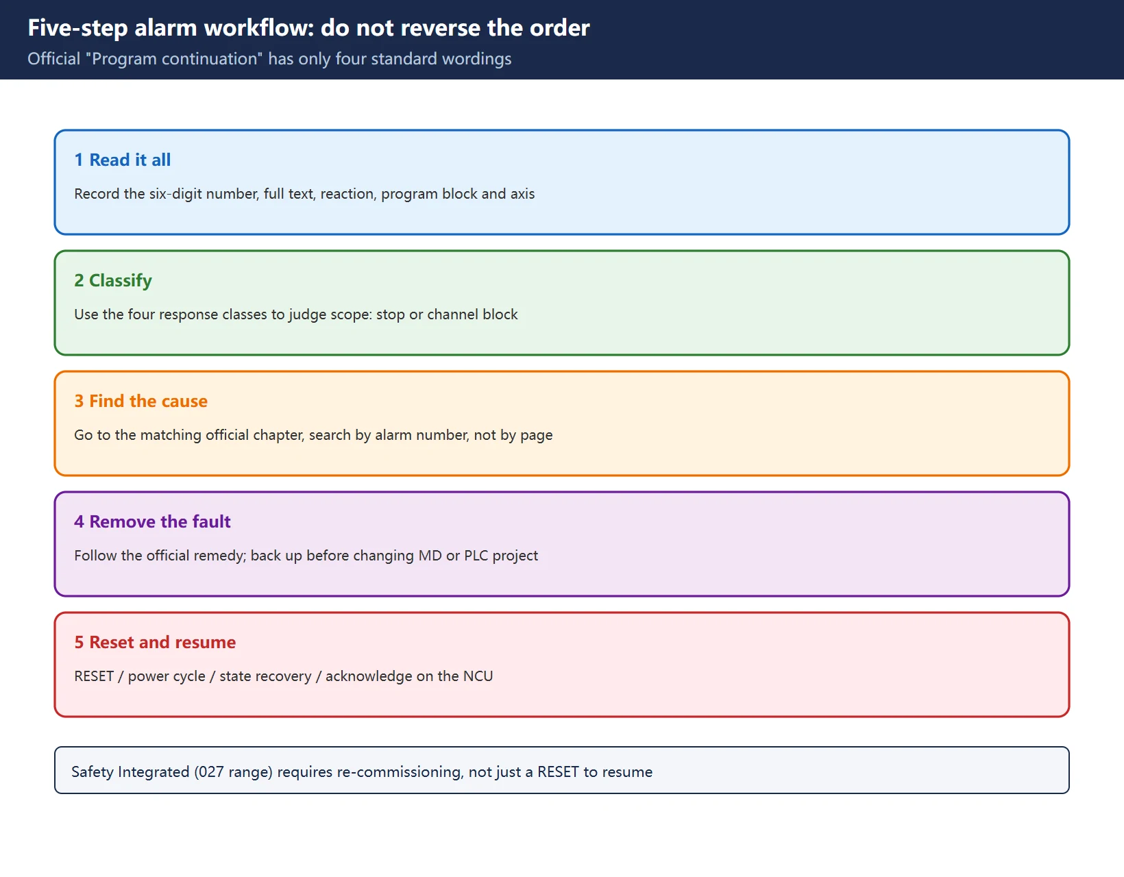
Every official alarm entry ends with a “Program Continuation” block. There are only four common forms, and a work order can quote them verbatim:
| Official Program Continuation wording | When it applies | Field action |
|---|---|---|
| Clear the alarm with the RESET key in all channels, restart the part program | Cause has been removed | Press RESET in every channel of the mode group, then restart |
| Switch control OFF – ON | Parameter, checksum or PLC start-up alarms | Power-cycle; save changes before the restart |
| Alarm display disappears when the cause is removed; no further operator action | Pure status messages | Confirm the state recovered, do not reset again |
| Acknowledge the alarm on the NCU | Serious NCU-level alarms | Acknowledge on that NCU, then continue as above |
Table 4 Four official Program Continuation forms and the matching action
Safety boundary: take a recoverable backup before changing CNC machine data or the PLC project. After clearing a Safety Integrated alarm (027 000 range), the official confirmation / acceptance test must be repeated; simply pressing RESET until the display clears is not a release back to production.
Official Manual: Chapter Index and Search Keys
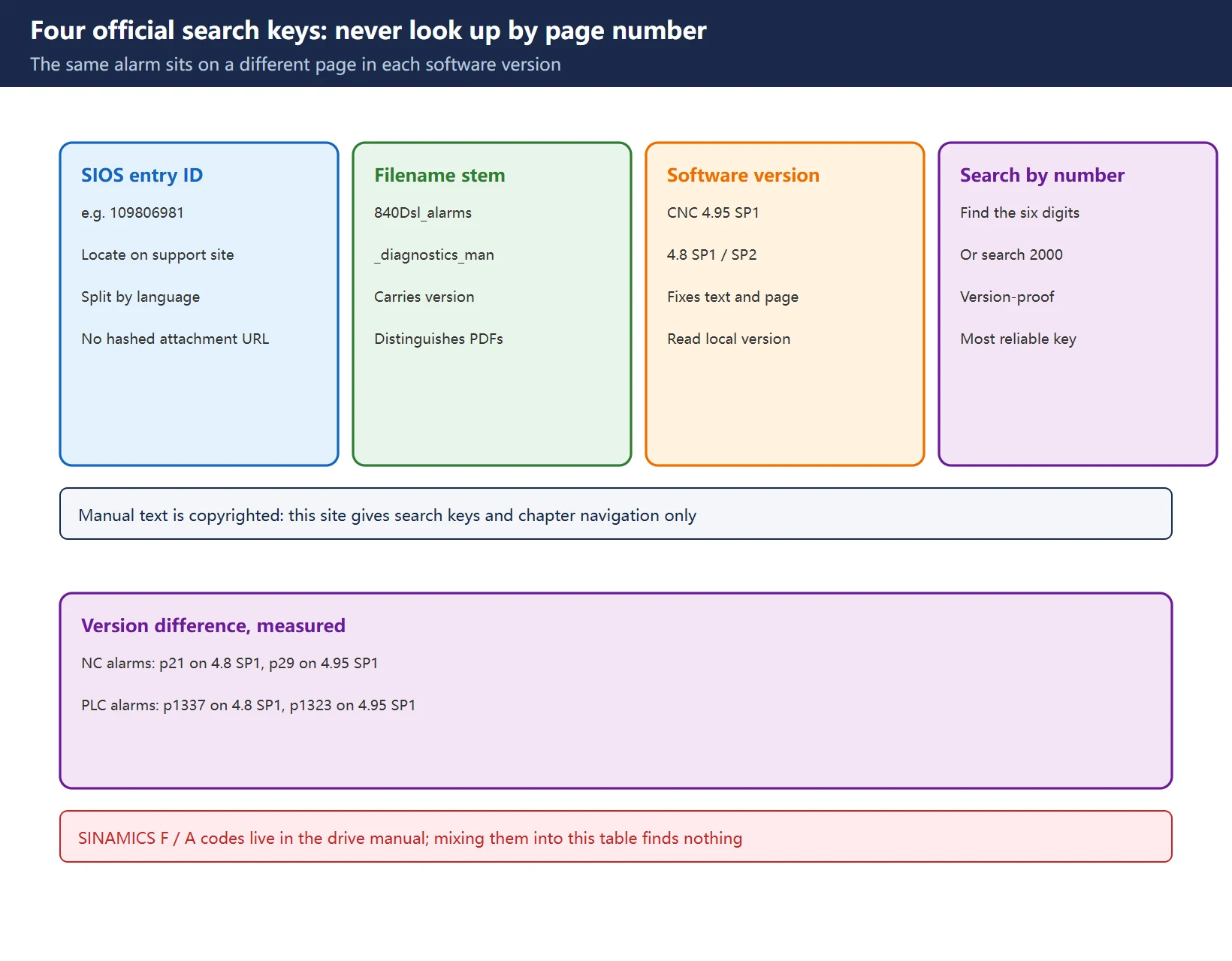
Do not look up alarms by page number. The same alarm sits on different pages in different software versions. Measured on this site in the diagnostics manual chapter guide: NCK alarms are on p21 in 4.8 SP1 but p29 in 4.95 SP1, and PLC alarms on p1337 in 4.8 SP1 but p1323 in 4.95 SP1.
| Search key | Official value / form | Purpose |
|---|---|---|
| SIOS entry ID | 109806981 (4.95 SP1, Chinese), 109748391 / 109752346 (4.8 family) | Locate the document on Siemens Support |
| Filename stem | 840Dsl_alarms_diagnostics_man_0122_zh-CHS | Distinguish version and language without a hashed attachment link |
| Software version | CNC 4.95 SP1 / 4.8 SP1 / 4.8 SP2 | Determines which page numbers and text apply |
| Full-text alarm search | Search the six-digit number (or 2000) inside the PDF | Works across versions |
Table 5 Four official search keys with measured version differences
Manual chapters follow the alarm families: NCK alarms, channel and axis alarms, Safety Integrated, Siemens cycles / user cycles, HMI, general PLC alarms, and SINAMICS drive faults and warnings. SINAMICS F / A codes belong to the drive manual, not the six-digit range table. Mixing them into this table is the usual reason nobody can find the text.
Which Team Owns This Alarm?
| Range | Primary owner | What to hand over |
|---|---|---|
000 000-029 999 | CNC / electrical commissioning | Full six-digit number, alarm text, Reaction block, program block and axis |
060 000-069 999 | Programming / process | Cycle number, call parameters, part program line |
100 000-199 999 | Operator / HMI | Screen, HMI version, triggering action |
400 000-499 999 | Electrical / PLC | PLC project version, DB bit address, online ladder state |
500 000-899 999 | Machine builder | Machine model, documentation number, builder's own alarm text |
700 000-799 999 | Builder / local project | Local PLC project backup (Siemens supplies no text) |
Table 6 Range-to-owner decision table: prepare this material before hand-over
Related Articles on This Site
| What you need | Page |
|---|---|
| Where the ranges come from, how to classify | |
| Cycle alarms 61000 / 62000 | |
| PLC basic program block call structure | |
| A different code system on the drive hardware |
Table 7 Further reading on this site
Frequently Asked Questions
Where can I find a complete SINUMERIK 840D sl alarm code list?
The complete per-number text exists only in Siemens’ official “SINUMERIK 840D sl / SINAMICS S120 Alarms Diagnostics Manual”. Find it on Siemens Support by entry ID (for example 109806981) and search the PDF by the full six-digit alarm number. Online excerpt tables are neither complete nor version-labelled, and they cannot contain text for the 500 000-899 999 builder range at all. This page provides the range map and the lookup method, not the manual text.
What does alarm 400000 mean on 840D sl?
400 000-499 999 is the general PLC alarm range, not a “machine data alarm” range, and a 4xxxx shorthand does not describe it. The meaning of a specific number such as 400000 depends on the text in the manual shipped with your machine or in the builder’s documentation: Siemens provides base text for part of this range, while builders configure their own alarms in the PLC project. Read the full six-digit number, the Reaction block and the interface signals on the alarm screen first, then trace the trigger condition in the PLC project.
Which manual section covers SINAMICS F-codes on 840D sl?
Use the SINAMICS S120 drive faults and warnings manual, not the six-digit range table. F means fault and A means warning, both reported by the drive itself under a numbering scheme separate from the six-digit NCK alarms. The 840D sl Alarms Diagnostics Manual also lists drive-related alarms, but looking for F... / A... in the NCK chapters under 0xxxxx or 2xxxxx will never find them.
Last updated: 2026-11-11
Official number range framework, reactions and manual chapter navigation
Where to go next
- FANUC Troubleshooting — the full guide library: alarms, diagnosis numbers, servo, spindle, PMC and electrical faults, organised by symptom.
- CNC Repair Tools — which instrument measures what: multimeters, clamp meters, insulation testers and oscilloscopes, with the specification that actually matters.
- Remote Technical Support — have the readings reviewed with you: alarm reverse lookup, PMC ladder analysis and servo tuning advice by call. Repair companies and integrators welcome.
Read the guide, get the right instrument, or walk the diagnosis through with someone — pick whichever you need.
The original Chinese version — same procedure, with the full field notes.


















暂无评论内容