


🚨 Scope and compliance: Alarm names, n1–n4 detail codes and remedies follow the published entries of Mitsubishi Electric *M800/M80/E80/C80 Series Alarm/Parameter Manual* (IB-1501279) and the official Mitsubishi FAQ on terminating resistors. The DA–DB / DA–DG wiring point, single-point shield grounding and the 0.5–0.8 N·m retorque figure come from public CC-Link field troubleshooting material and are marked as field practice. Manual text is copyright protected: this article gives number-level navigation and a troubleshooting path only, provides no download link, file mirror or crack, and does not reproduce manual pages. Always confirm against the manual matching your installed software version.
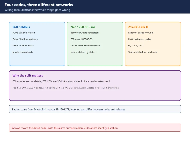
30-Second Triage
Table 0. Six presentations and the first checkpoint
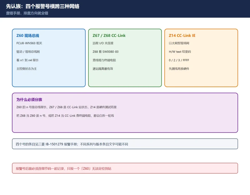
1. Know the Families: Four Codes, Three Networks
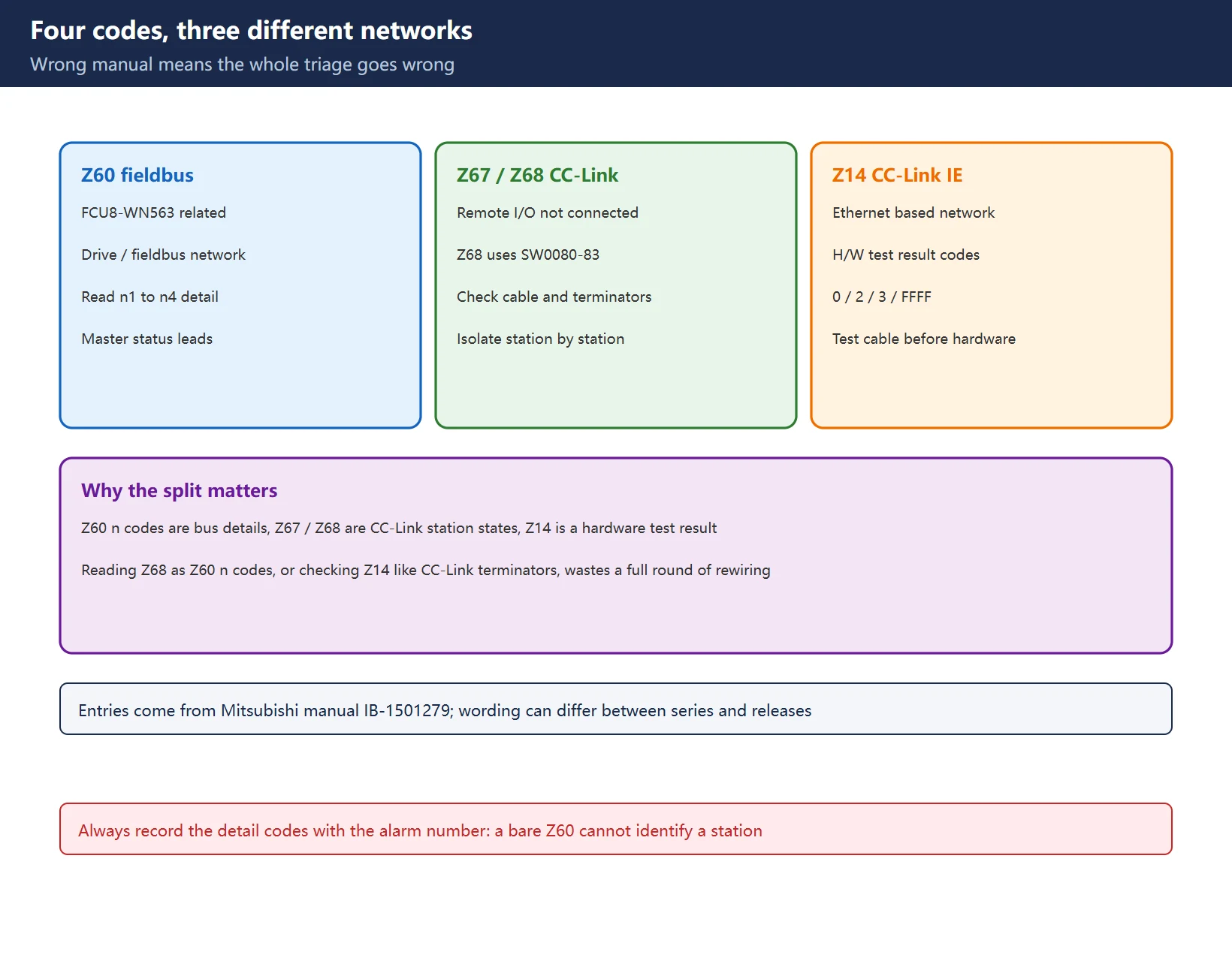
| Code | Official entry name | Network / hardware | Main pointer |
|---|---|---|---|
| Z60 | Fieldbus communication error n1 n2 n3 n4 | Fieldbus communication with FCU8-WN563 | n4 refers to the *PROFIBUS-DP Specification manual* |
| Z67 | CC-Link communication error | Communication using the CC-Link unit | Message list in CC-Link (Master/Local) specification manual BNP-C3072-089 |
| Z68 | CC-Link unconnected | Cable between CC-Link unit and a device | Find the unconnected cable via SW0080–SW0083 |
| Z14 | CC-Link IE F H/W test status n1 n2 | CC-Link IE Field network unit | n1/n2 = slot 1 / slot 2 results; remedies involve Ethernet cable |
Table 1. Four codes and their networks (IB-1501279 entries)
This is not pedantry. Z60’s n4 points to a PROFIBUS-DP specification manual, Z14’s remedy says “exchange the Ethernet cable”, and Z68’s remedy is to find a broken CC-Link dedicated cable. Applying the Z68 method to Z14 means hunting for DA/DB terminals on a unit that does not have them. For a comparable “read the alarm family before acting” approach on another controller, see the SINUMERIK 840D sl alarm list by number range.
2. Reading Z60’s n1–n4
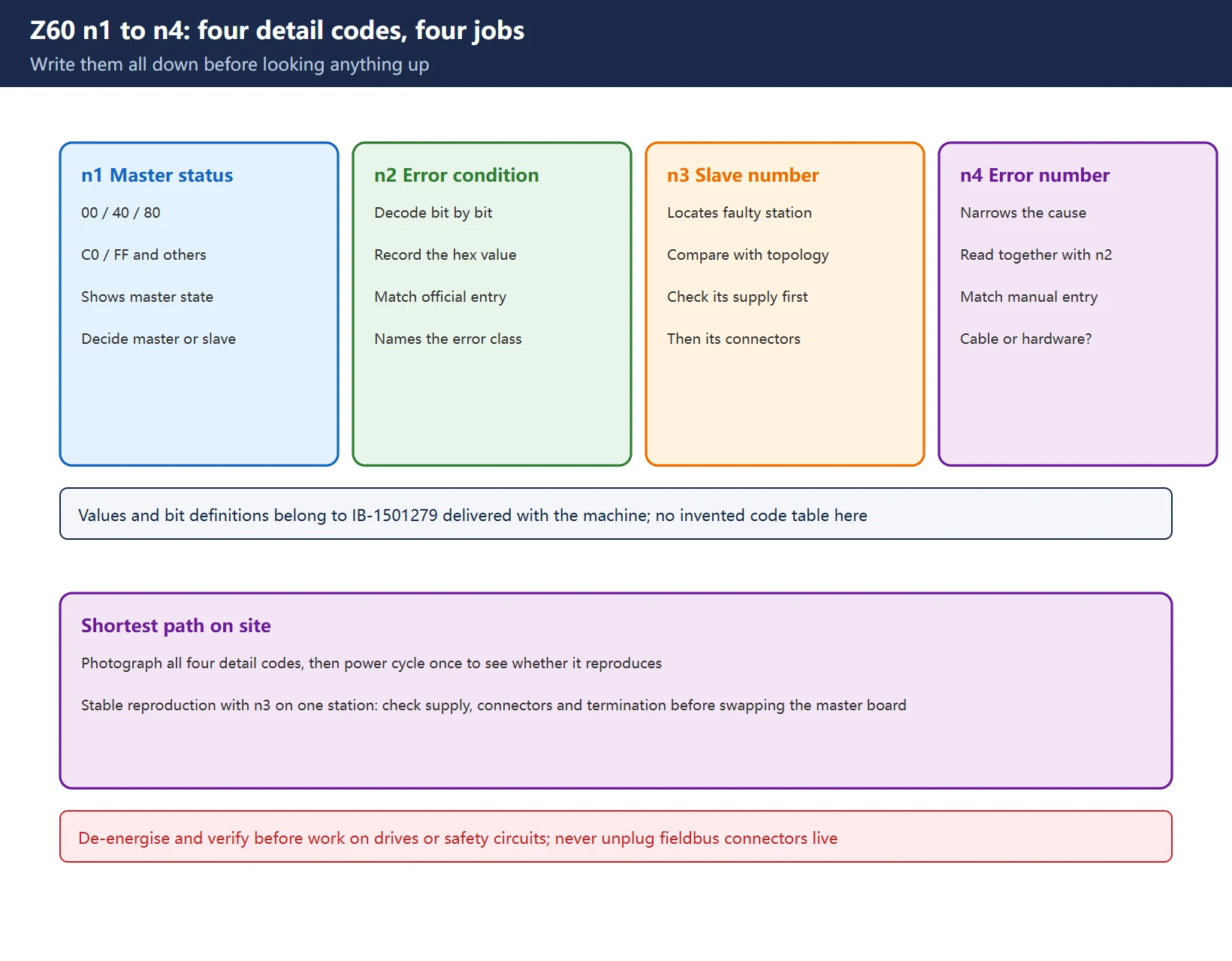
The official entry defines all four detail codes, in hexadecimal:
n1 = master station status
| Value | Meaning |
|---|---|
| 00 | Offline: in initialization |
| 40 | Stop: I/O communication stopped |
| 80 | Clear: resetting each slave's output data by sending zero data |
| C0 | In operation: in I/O communication |
| FF | Two Fieldbus expansion units are mounted |
n2 = error condition (bit-wise)
| Bit | Meaning |
|---|---|
| bit0 | Control error: parameter error |
| bit1 | Auto clear error: communication with all slaves was cut because one slave had an error |
| bit2 | Non-exchange error: a slave station has a communication error |
| bit3 | Fatal error: communication cannot continue because of severe network failure |
| bit4 | Not ready: CNC communication is not ready |
| bit5 | Timeout error: timeout detected in communication with each station |
| bit6 / bit7 | Not used |
| FF | Two Fieldbus expansion units are mounted |
n3 is the slave station where the error occurred (hex; FF when two expansion units are mounted). n4 is the error number; the manual explicitly says “For details, refer to PROFIBUS-DP Specification manual”.
Table 2. Z60 n1 / n2 detail (IB-1501279 entry)
Field reading order: use n1 to see whether the master ever reached operation; use n2 bits 1/2 to distinguish “one station dropped” from “whole network auto-cleared”; n3 gives the station number so you can go straight to a physical check; do not guess n4 — look the number up in the referenced specification manual. 🚨 Do not apply Z60’s n1–n4 structure to Z67/Z68; those entries do not carry four detail codes.
3. Z68 Unconnected: Locating the Segment with SW0080–SW0083
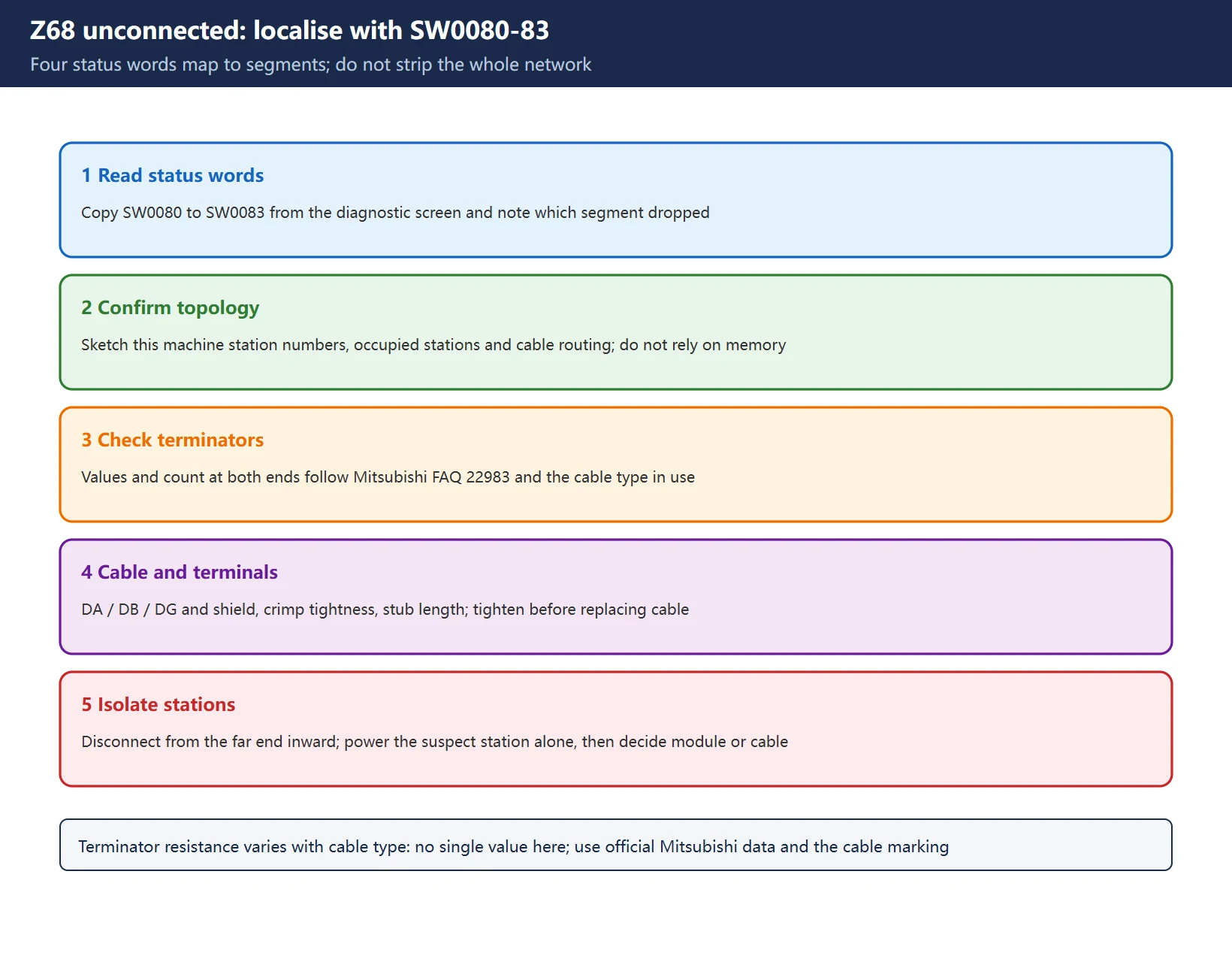
The official Z68-000 CC-Link unconnected entry states: a cable between the CC-Link unit and a device is disconnected or broken, and the remedy is to “find the unconnected cable by checking SW0080 to SW0083 and connect it”. These four status words are the fastest way to identify which segment is open — much faster than pulling every terminal.
Field sequence:
- Read
SW0080–SW0083on the diagnostic screen and identify the open segment / station; - Inspect only that segment: cable jacket, crimp, DA / DB / DG terminal tightness;
- If the status words point to several segments, check the two trunk ends and the terminating-resistor stations first;
- After reconnecting, power-cycle and confirm — do not mask a poor contact with repeated resets.
Table 3. Official Z68 entry and segment-by-segment actions
🚨 The exact bit assignment, station mapping and refresh timing of SW0080–SW0083 depend on the installed version; take them from the matching manual and PLC screen — this article invents no bit table. Z67 belongs to CC-Link too, but its official entry is a “communication error” whose remedy points to the CC-Link specification manual’s message list, not a broken cable. Before changing any PLC-side configuration, keep a recoverable project backup following the discipline described in SINUMERIK PLC basic program: FB1, FB2 and OB100 (different vendor, same backup-first rule).
4. Interpreting Z14 H/W Test Results
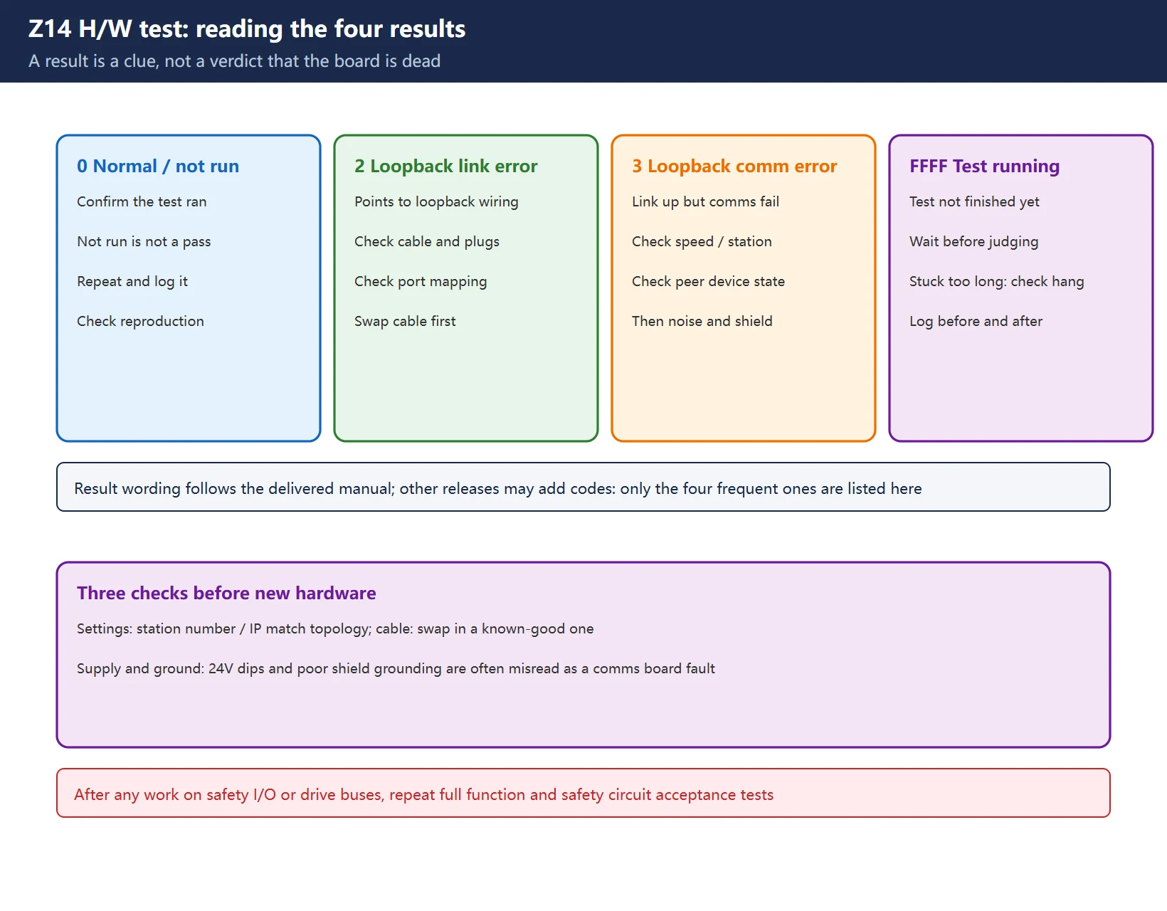
The official name of Z14 is CC-Link IE F H/W test status n1 n2: n1 is the test result of slot 1, n2 that of slot 2, both hexadecimal.
| Result | Official meaning | Official remedy direction |
|---|---|---|
| 0 | H/W test normally completed, or not performed | If the mode is H/W test, switch to online and cycle NC power; otherwise check the other slot's result |
| 2 | External self-loopback test completed with connection error | Check the Ethernet cable connection or exchange the cable, retest; if it repeats, exchange the hardware |
| 3 | External self-loopback test completed with communication error | Exchange the Ethernet cable, retest; if it repeats, exchange the hardware |
| FFFF | H/W test is underway | Cycle NC power; if unchanged, exchange the hardware |
Table 4. Z14 results and remedies (IB-1501279 entry)
🚨 Two traps. First, Z14 tests the CC-Link IE Field network unit over Ethernet cable — the remedy says Ethernet cable, not the CC-Link dedicated DA/DB cable. Second, result 0 does not automatically mean “all clear”: if the mode is still H/W test, you must switch back to online and cycle power, or the network will never enter normal communication.
5. Three Frequent CC-Link Wiring Mistakes
The following apply to the CC-Link dedicated-cable network of Z67 / Z68, not to the Ethernet side of Z14.
1. Terminating resistor on the wrong terminals. The resistor goes between DA and DB at the two ends of the segment — not DA to DG. A DA–DG resistor gives incorrect termination, causes reflections and shows up as intermittent station dropouts. Intermediate stations must have no terminating resistor; exactly one at each end.
2. The value is not always 110 Ω. Mitsubishi’s official FAQ distinguishes by cable type:
| Cable type | Terminating resistor (between DA and DB) |
|---|---|
| Ver.1.10-compatible CC-Link dedicated cable | 110 Ω, 1/2 W |
| CC-Link dedicated cable (Version 1.00) | 110 Ω, 1/2 W |
| CC-Link dedicated high-performance cable (Version 1.00) | 130 Ω, 1/2 W |
Table 5. Mitsubishi official FAQ 22983 terminating resistor values
The popular “always 110 Ω” rule is wrong for high-performance cable — a point most summary articles omit. Identify the cable by its printed type designation, then compare with the table; a meter across DA–DB at the end station should agree with the selected type.
3. Shield grounded at both ends. The shield should be grounded at one end only (normally the master). Grounding both ends forms a ground loop, injects noise and produces intermittent communication errors. To check, disconnect one end and test shield-to-ground continuity.
A fourth common item is terminal loosening under vibration: even if tightened at commissioning, a single station’s DA / DB / DG can work loose and cascade into a whole-segment fault. Public field material quotes a retorque reference of 0.5–0.8 N·m (field practice; follow the terminal vendor’s specification). Intermediate and hard-to-see stations are the ones usually missed.
6. Station-by-Station Isolation and Cable Integrity Tests
| Step | Action | Criterion |
|---|---|---|
| 1 | Record station numbers, baud rate, scan time and alarm detail codes | Baseline for rollback |
| 2 | With power off, measure resistance between DA and DB | Matches the resistor for the installed cable type |
| 3 | Continuity-test DA, DB, DG; check for shorts between conductors and to shield | No opens, no shorts |
| 4 | Test shield-to-ground continuity, confirm single-point grounding | No ground loop |
| 5 | Disconnect / reconnect stations one at a time, see whether the fault follows one node | Faulty node identified |
| 6 | After restoration, confirm terminators exist only at the two ends | No intermediate resistor |
Table 6. Isolation and cable integrity checklist
Keep the downtime window short: narrow the range with SW0080–SW0083 and n3 first, then open only the suspect segment rather than rebuilding the whole network. For the general habit of reading a controller’s reported diagnostic state before touching hardware, compare the FANUC A06B amplifier 7-segment code table and SINUMERIK 828D cycle alarms — different systems, same discipline. Symbol-name discipline on the PLC side is illustrated in the 828D third handwheel and Mini HHU guide.
Safety: isolate power, verify absence of voltage and apply LOTO before touching terminals. Measuring DA/DB live or hot-plugging communication cables can damage interface modules. On networks carrying safety-related I/O, perform a full functional verification after restoration — a cleared alarm alone is not proof of recovery.
7. How This Page Relates to the Rest of the Site
Table 7. Related pages and how they differ
This page gives number-family separation and a physical-layer path only. It does not reproduce manual pages and offers no third-party packaged manuals or file mirrors; for n4 error numbers, SW bit assignments or the message list, look up the number in the delivered documentation or the machine tool builder’s support channel.
Frequently Asked Questions
What does Mitsubishi M80 CC-Link alarm Z68 mean?
The official entry is “CC-Link unconnected”: a cable between the CC-Link unit and a device is disconnected or broken. It is a physical cable fault, not a parameter error, and the official remedy is to find the unconnected cable by checking SW0080 to SW0083 and reconnect it. Note that Z68 differs from Z67 (CC-Link communication error) and sits on a different network from Z60 (FCU8-WN563 fieldbus) and Z14 (CC-Link IE Field hardware test).
How do I read Z60 fieldbus communication error n1 n2 n3 n4?
Per IB-1501279: n1 is the master status (00 initialization / 40 stop / 80 clear / C0 in operation / FF two expansion units mounted); n2 is the bit-wise error condition (bit0 parameter, bit1 auto clear, bit2 non-exchange, bit3 fatal, bit4 not ready, bit5 timeout, bits 6/7 unused); n3 is the faulty slave station number; n4 is an error number whose details are in the *PROFIBUS-DP Specification manual*. Check n1 first to see whether the master reached operation, use n2/n3 to reach the station, and look up n4 in the referenced manual rather than guessing.
How is the CC-Link terminating resistor connected, and to which terminals?
Between DA and DB at each of the two segment ends, with none at intermediate stations; DA–DG is the classic mistake. Select the value by cable type: 110 Ω / 1/2 W for Ver.1.10-compatible dedicated cable and Ver.1.00 dedicated cable, but 130 Ω / 1/2 W for Ver.1.00 dedicated high-performance cable (Mitsubishi official FAQ 22983) — so “always 110 Ω” is not correct. Also confirm the shield is grounded at one end only and retorque terminals to the vendor specification. Z14 belongs to the CC-Link IE Field Ethernet side and does not use this DA/DB wiring.
Last updated: 2026-11-10
Where to go next
- FANUC Troubleshooting — the full guide library: alarms, diagnosis numbers, servo, spindle, PMC and electrical faults, organised by symptom.
- CNC Repair Tools — which instrument measures what: multimeters, clamp meters, insulation testers and oscilloscopes, with the specification that actually matters.
- Remote Technical Support — have the readings reviewed with you: alarm reverse lookup, PMC ladder analysis and servo tuning advice by call. Repair companies and integrators welcome.
Read the guide, get the right instrument, or walk the diagnosis through with someone — pick whichever you need.
The original Chinese version — same procedure, with the full field notes.

















暂无评论内容