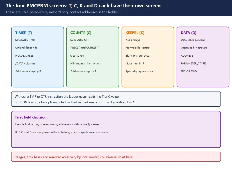



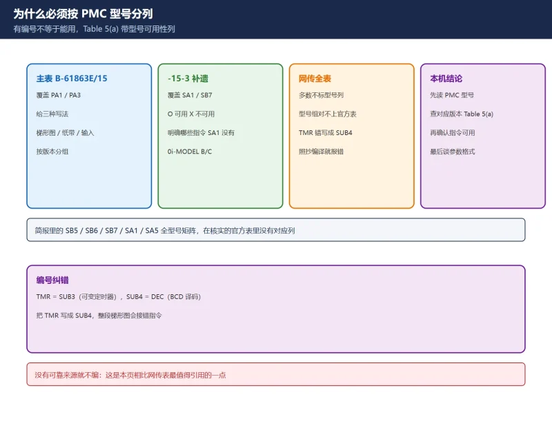
Scope and compliance: The screen names, soft keys, fields and address increment evidence on this page come from the public FANUC PMC Ladder Language Programming Manual (
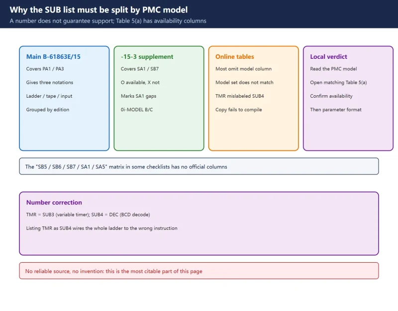
B-61863E/15, Chapter 4, PMC PARAMETERS SETTING AND DISPLAY / PMCPRM) and the FANUC Series 0i-MODEL C / 0i Mate-MODEL C Maintenance Manual (B-64115EN/01, section 4.3.4 PMC Parameter). This page does not reproduce original manual tables, complete per-address range charts or page numbers, and provides no manual download, file mirror or archive bundle. Address ranges, timer time bases, reserved area boundaries and screen labels vary with the PMC model (SA1 / SB5 / SB6 / SB7 / NB and others), the CNC series and the software version. Circulating “universal address tables” contradict each other and are not used here; always check the local PMCPRM screens and the documentation supplied with the machine. Anything uncertain is marked as needing on-site verification.
30-Second Triage: Which Screen Do You Need?
Table 0 Seven field tasks and their first PMCPRM destination
1. The Four PMCPRM Screens
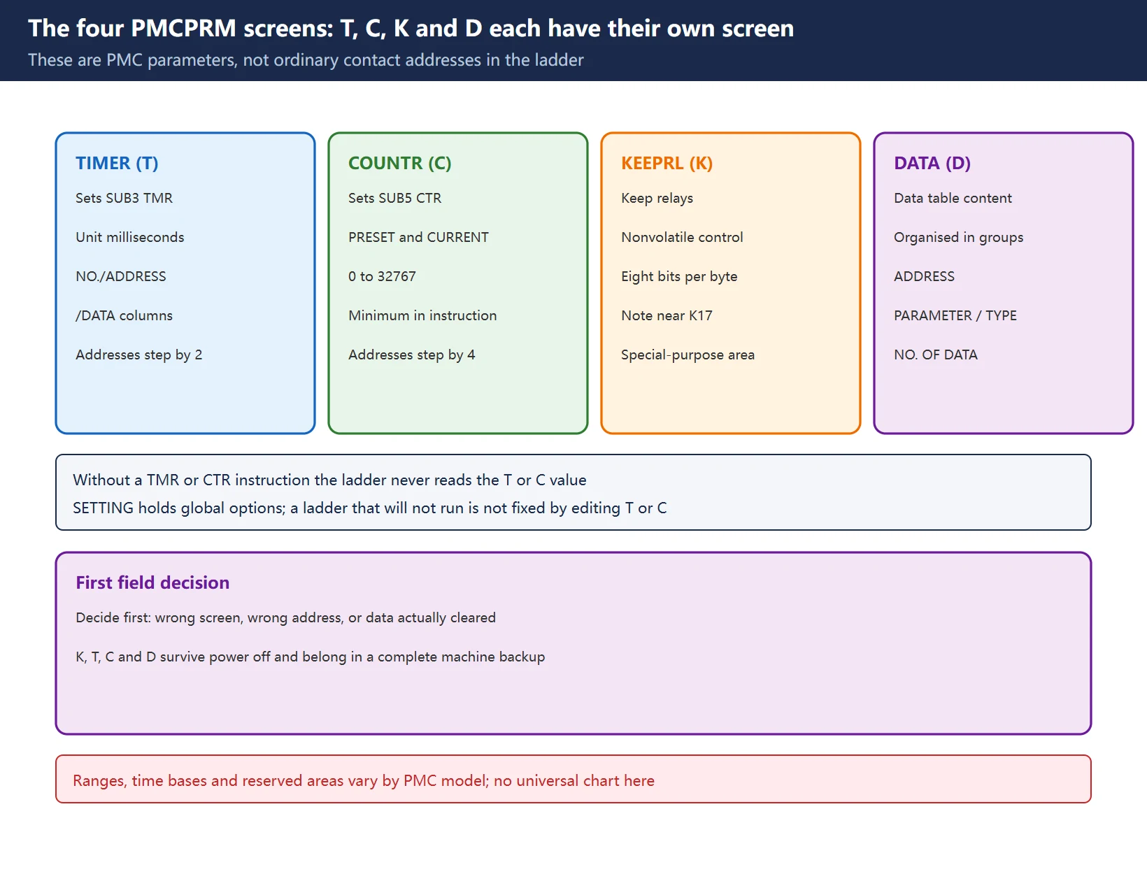
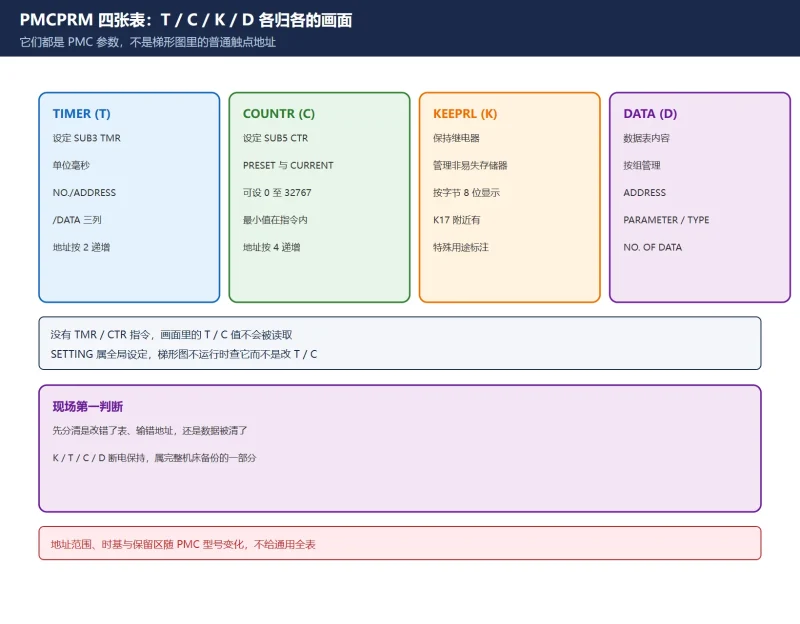
The official manual maps the four PMCPRM screens one-to-one onto four address classes:
| Soft key / screen | Address | Official role | Typical consequence if wrong |
|---|---|---|---|
[TIMER] | T | Sets the time for the TMR function instruction (SUB 3), in milliseconds | Timeout logic never becomes true, or is true from the start |
[COUNTR] | C | Sets and displays PRESET (maximum) and CURRENT for the CTR function instruction (SUB 5) | Count never completes, magazine cycle misaligns |
[KEEPRL] | K | Sets and displays keep relays and the data controlling nonvolatile memory | Magazine counts clear after power off, wrong tool after homing |
[DATA] | D | Data table contents and data table control data, organised in groups | Offset or recipe data reads back as defaults |
Table 1 The four PMCPRM screens mapped to T / C / K / D (summarised from the official manual; screen labels follow the local display)
Three points are worth separating:
- They are not the same as
Rinternal relays.Ris bit scratch memory inside the ladder, whileK / T / C / Dare PMC parameters. The manual describes the KEEPRL screen as covering keep relays and the data controlling nonvolatile memory, which means these four classes survive power off and belong in a complete machine backup. In the field they are normally maintained by the CNC backup battery, so a dead battery, a general clear or a restore can return them to defaults. Back up before changing anything and verify the retention mechanism against the supplied manual (on-site verification required). For model differences see FANUC PMC Troubleshooting: 5 Real Cases and What Is a PMC in Fanuc. TandConly matter when the matching function instruction is in the ladder. The screen descriptions nameSUB 3for TIMER andSUB 5for COUNTR explicitly; without a TMR or CTR instruction in the sequence program, the number on the screen is never read. For instruction numbers and model availability see FANUC PMC Functional Instruction (SUB) Quick Reference; for the ladder basics see FANUC PMC Ladder Diagram Beginner Tutorial.- A fifth
SETTING]screen holds global settings such as ladder run state and I/O allocation, and is outside these four. “Ladder not running” belongs there, not in T or C. The four diagnostic screens are compared in [Fanuc 0i-MD PMC Diagnostic Screens.
2. Byte Structure: T Uses 2 Bytes, C Uses 4
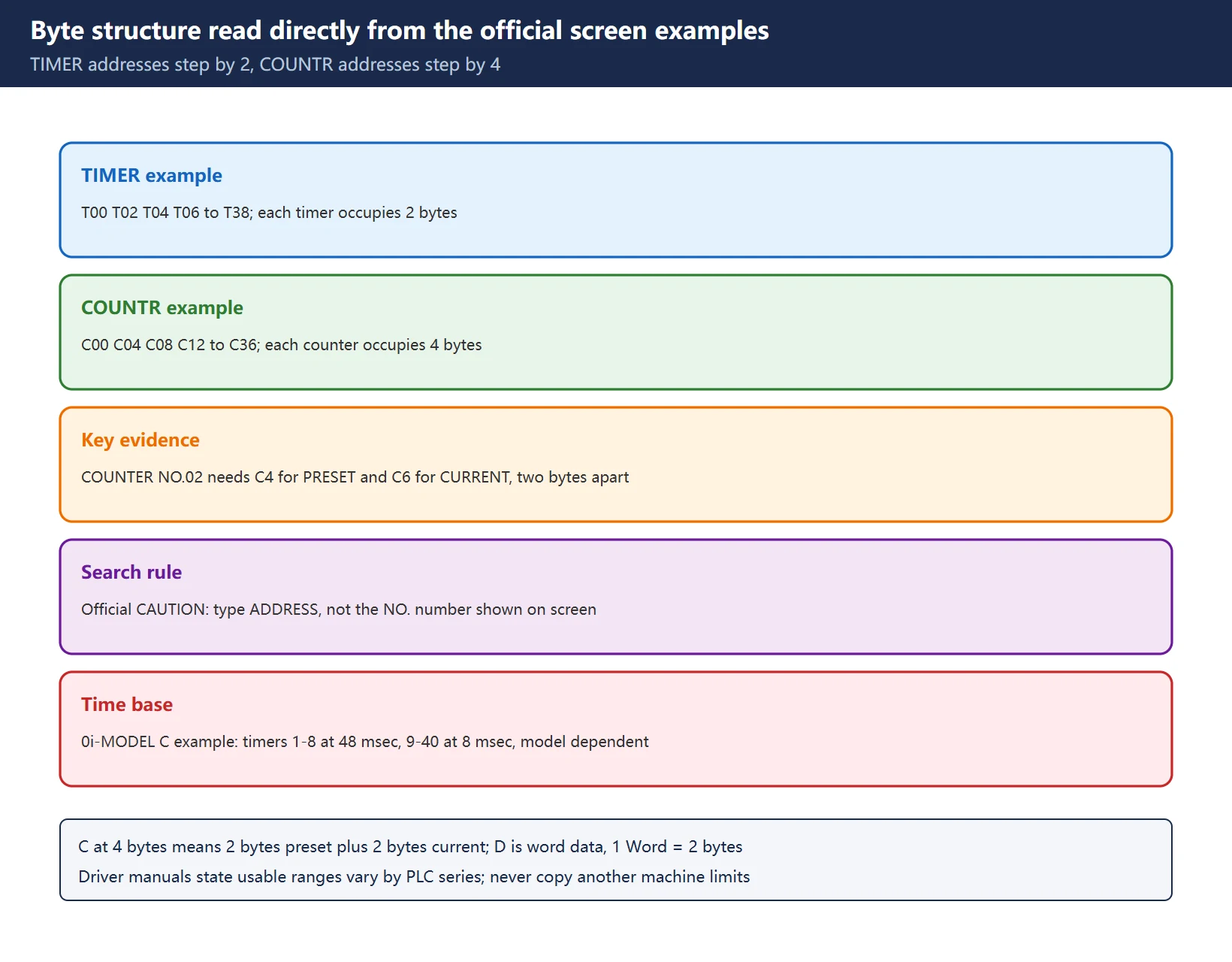
You do not need a “universal range table” here — the address increment in the official screen examples is enough:
| Screen | Address sequence in the official example | What it tells you |
|---|---|---|
| TIMER | T00, T02, T04, T06 through T38 (increment 2 per row) | Each timer occupies 2 bytes; columns are NO. / ADDRESS / DATA |
| COUNTR | C00, C04, C08, C12 through C36 (increment 4 per row) | Each counter occupies 4 bytes; columns are NO. / ADDRESS / PRESET / CURRENT |
| COUNTR range | The manual states 0-32767 can be set for PRESET and CURRENT; the minimum is specified in the CTR instruction | Do not confuse the counter number with a numeric limit |
| TIMER time base | 0i-MODEL C example: timers 1-8 up to 1572.8 s at 48 msec resolution; timers 9-40 up to 262.1 s at 8 msec | Model and version dependent, not portable to 0i-F or 30i |
Table 2 Address increments and time bases read from official screen examples (values illustrate structure only; check the local control)
🚨 The single most revealing official example is in the manual’s search instructions: to set COUNTER NO.02, you press [COUNTR] and type C4 for PRESET but C6 for CURRENT (the letter C may be omitted). In other words the preset and the current value are two different addresses two bytes apart — direct evidence that one counter occupies 4 bytes (2 bytes preset plus 2 bytes current). Likewise, setting TIMER NO.11 means typing ADDRESS T20, not the number 11; the manual adds an explicit caution that you type the address (ADDRESS), not the number (NO.), when searching.
The same trap exists on the external device side. The Pro-face FANUC driver manual lists word addresses with 1 Word = 2 bytes and separate High / Low bytes, and states plainly that the actual usable address range varies with the PLC series. So do not copy one machine’s K / T / C / D limits into a general chart, and do not mix bit addresses with word addresses.
3. KEEPRL and Reserved Areas
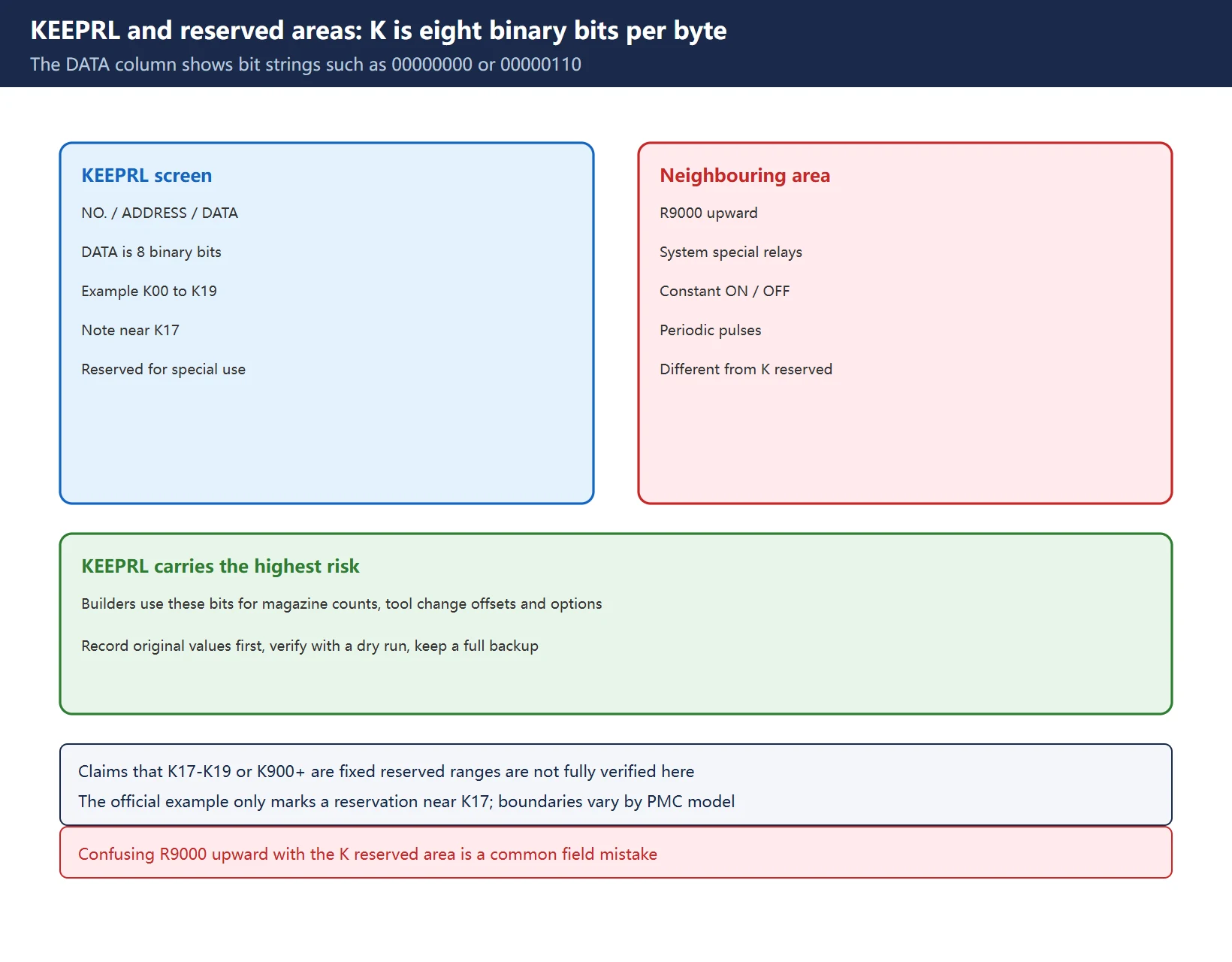
The official KEEPRL example uses NO. / ADDRESS / DATA columns, with DATA shown as eight binary digits (for example 00000000 or 00000110). That tells you K is read and written byte by byte and bit by bit — a completely different usage from the word data in D or the numeric settings in T and C:
- The example runs from
K00up toK19and carries a note marking the area aroundK17as reserved for special use. Circulating lists often callK17-K19orK900+fixed system reserved ranges; our verification only supports the statement that the official example marks a special-purpose reservation near K17. The exact reserved boundary varies with the PMC model, so follow the local screen hints and the supplied manual rather than a chart from the internet. - A neighbouring but separate reserved class is the
R9000upward special relays (system-reserved constant ON / OFF and periodic pulses), covered in Fanuc PMC R9000 System Relays Explained.R9000+and the K reserved region are two different things. - Retentive addresses are also discussed under
D,EandEPon older controls, where the power-off retention range differs considerably from 0i-F and later. See Fanuc PMC Program: Edit on PC and Send Back to NC for project handling and FANUC PMC Project From Scratch for the backup-to-verification flow.
Table 3 How to reason about K and adjacent reserved areas (always check the reserved boundary against the local PMC model)
🚨 KEEPRL carries the highest risk of any edit. Machine builders use these bits for magazine counts, tool change offsets and option switches. Adjusting T or C settings during commissioning only affects timing and is relatively low risk; before editing KEEPRL, record every original value, then verify with a dry run, and make sure a complete backup exists (see How to Export / Print FANUC Parameter Tables and Ladder Programs and How to Backup and Restore a Fanuc PMC Program). For signal-level checks see How to Use FANUC PMC Force Output.
4. DATA Is Group Based: Four Control Data Fields
[DATA] is not one flat table: it is organised in groups. The manual lists four “data table control data” fields: ADDRESS, PARAMETER, TYPE and NO. OF DATA. Its worked example follows this order:
- On the control data screen, type the group number and press
[NO.SRH]to move the cursor toADDRESS. - Enter the start address (example
D20, where the letterDmust not be omitted); pressingINPUTadvances the cursor toPARAMETER, and the four fields are completed in sequence. - Press
[G.DATA]to open the data table screen, then use[G-SRCH]with the group number to display that group. - Use
[SEARCH]with the address to change (exampleD22, whereDmay be omitted), then pressINPUTto write the value.
Table 4 The four data table control fields and their soft keys (summarised from the official worked example; labels vary by control)
So when offset or recipe data reads back as defaults, first decide whether the control data (group number, start address, type, number of data) is wrong, or whether the data inside the group was cleared. The first is fixed on the DATA] control screen; only the second needs a restore. For how D is confused with R and K in ladder work, see [Fanuc PMC Alarm Codes Explained and FANUC PMC Troubleshooting: 5 Real Cases.
5. Six Steps to Write PMC Parameters from MDI
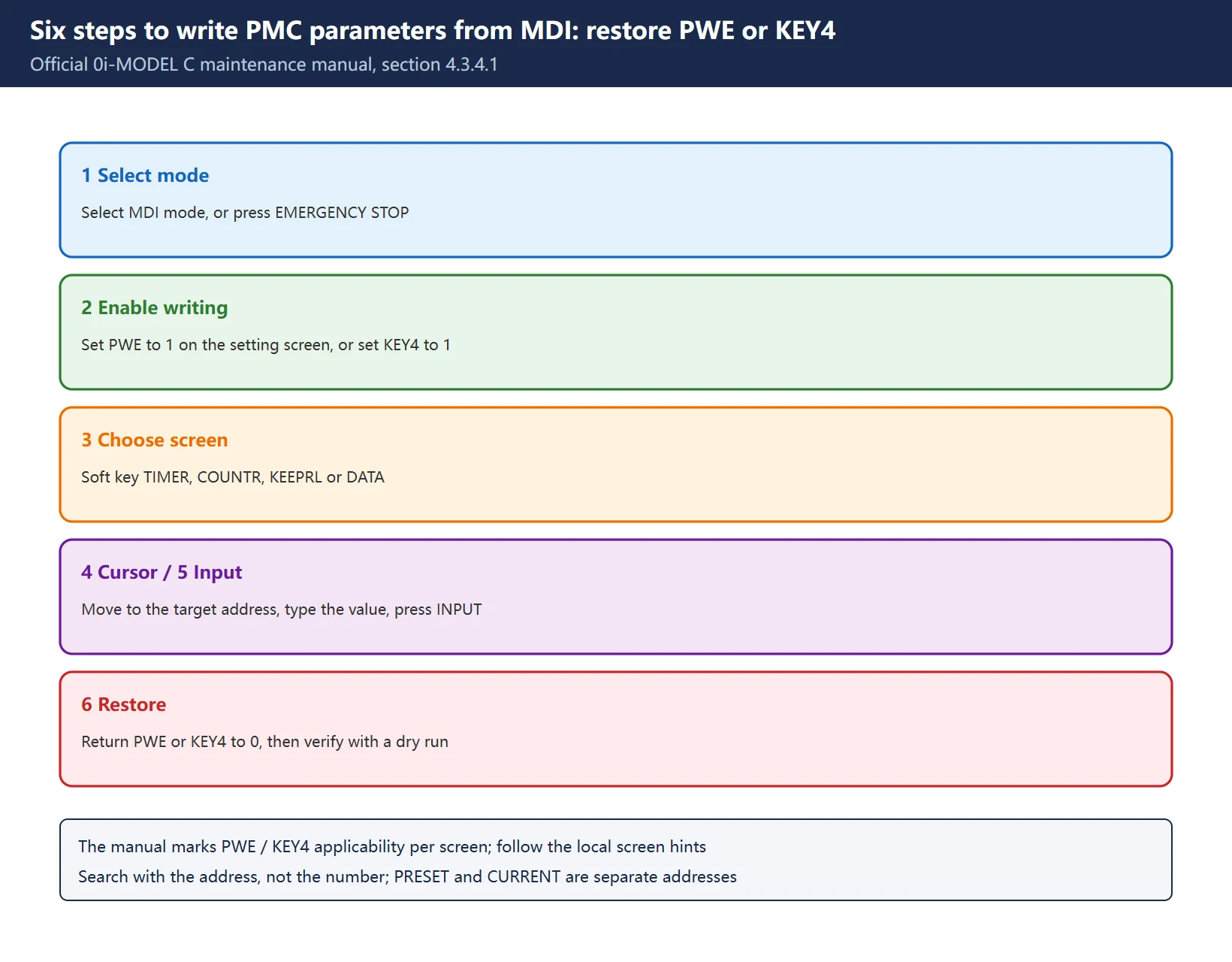
Section 4.3.4.1 “Input of PMC parameter from MDI” in the 0i-MODEL C maintenance manual gives six steps:
| Step | Action |
|---|---|
| 1 | Select MDI mode, or press EMERGENCY STOP |
| 2 | Set PWE to 1 on the setting screen, or set the program protect signal KEY4 to 1 |
| 3 | Choose the screen with a soft key: [TIMER] / [COUNTR] / [KEEPRL] / [DATA] |
| 4 | Move the cursor to the target number or address |
| 5 | Type the value and press INPUT |
| 6 | After setting, return PWE or KEY4 to 0 |
Table 5 The six MDI write steps (the manual marks PWE / KEY4 applicability per screen; follow the local screen hints)
Three recurring mistakes:
- Searching with the on-screen
NO.instead of the address. The manual flags this with aCAUTION:TIMER NO.11needsT20;COUNTER NO.02needsC4for PRESET andC6for CURRENT. - Forgetting to return
PWE/KEY4to zero. Besides leaving write access open, this affects later parameter work. The manual makes it step 6, not an option. - Returning to production without verification. At minimum do a dry run or signal trace to confirm the ladder actually reads the new timer or counter value; How to Use FANUC PMC Force Output and the signal tracing cases in FANUC PMC Troubleshooting: 5 Real Cases help here. Online editing and RUN / EDIT switching risks are covered in FANUC PMC Project From Scratch.
6. Scope and compliance
This page provides only officially verifiable screen roles, field structures, address increment evidence and the write procedure. It does not supply a complete per-address range chart, a model availability matrix or manual page numbers, because PMC models (SA1, SB5, SB6, SB7, NB and others), CNC series and software versions change address limits, timer time bases, reserved boundaries and screen labels at the same time. Circulating ranges such as “K0-K19 / K39”, “T0-T79 / T299”, “C0-C79 / C199” and “D0-D1859 / D7999” come from inconsistent sources and would mislead a technician if presented as a universal table. No manual text is reproduced, and no download, file mirror, archive bundle or third-party mirror is provided. Check every value against the local PMCPRM screen, the PMC model and the documentation supplied with the machine; anything uncertain is marked as needing on-site verification. Manual numbers and chapter names appear only as lookup keys, never as page citations.
7. Related pages on this site
- PMC parameters and screens: FANUC PMC Functional Instruction (SUB) Quick Reference · Fanuc 0i-MD PMC Diagnostic Screens · What Is a PMC in Fanuc · FANUC PMC Ladder Diagram Beginner Tutorial
- Retention and reserved areas: Fanuc PMC R9000 System Relays Explained · FANUC PMC Program: Edit on PC and Send Back to NC · FANUC PMC Project From Scratch
- Field techniques: How to Use FANUC PMC Force Output · FANUC I/O Link Address Assignment · Fanuc PMC Alarm Codes Explained · FANUC PMC Troubleshooting: 5 Real Cases
- Backup and restore: How to Export / Print FANUC Parameter Tables and Ladder Programs · How to Backup and Restore a Fanuc PMC Program
Frequently Asked Questions
Do T, C, K and D always survive a power cycle?
The official manual describes the KEEPRL screen as covering keep relays and the data controlling nonvolatile memory, so these four PMC parameter classes are designed to be nonvolatile and retained across power off. Whether they actually are depends on the backup battery, whether a general clear or restore was performed, and the implementation of that PMC model. A dead battery, a lost SRAM backup or a default restore can return them to defaults. That is why this page recommends recording original values and taking a full backup before editing, then verifying with a dry run; confirm the retention mechanism against the supplied manual and the local machine (on-site verification required).
Why does searching by the number shown on the COUNTR screen find nothing?
Because the official procedure expects the address (ADDRESS), not the display number (NO.). The manual’s example says that setting COUNTER NO.02 requires typing C4 for PRESET and C6 for CURRENT, and setting TIMER NO.11 requires T20. The reason is the byte structure: each T number occupies 2 bytes and each C number 4 bytes (2 bytes preset plus 2 bytes current), so addresses increment by 2 or 4 and do not track the row number shown on screen.
Can you just give a universal K / T / C / D address range chart?
No, and it would be unsafe. Both the official material and external driver manuals state that the usable address range varies with the PLC / PMC series. Ranges differ widely between PMC models (SA1, SB5, SB6, SB7, NB and others) and CNC series, and the charts circulating online contradict each other. This page gives only structure that can be verified directly from official screen examples (T increments by 2, C by 4, K shown as eight binary bits per byte, D organised in groups); check the actual limits on the local PMCPRM screen and in the manual supplied with the machine.
Last updated: 2026-11-11
Where to go next
- FANUC Troubleshooting — the full guide library: alarms, diagnosis numbers, servo, spindle, PMC and electrical faults, organised by symptom.
- CNC Repair Tools — which instrument measures what: multimeters, clamp meters, insulation testers and oscilloscopes, with the specification that actually matters.
- Remote Technical Support — have the readings reviewed with you: alarm reverse lookup, PMC ladder analysis and servo tuning advice by call. Repair companies and integrators welcome.
Read the guide, get the right instrument, or walk the diagnosis through with someone — pick whichever you need.
The original Chinese version — same procedure, with the full field notes.























暂无评论内容