


Scope and compliance: The number ranges, reaction terminology, user alarm interface layout and the
25050entry on this page come from the public SINUMERIK 802D sl Diagnostics Manual (software version 1.4, order number 6FC5398-2CP10-1RA0), the 802D sl Function Manual Axis Monitoring (A3) chapter, and the 802D sl manual section on PLC alarms. They are cross-checked against the framework in our SINUMERIK 828D alarm number range chart. This page does not reproduce per-alarm manual text, page numbers or complete code tables, and provides no manual download, file mirror or archive bundle. Some third-party “802D sl alarm number allocation” charts conflict with the official tables (for example calling010 000 - 019 999an NCK channel range when the manual calls it the ISO alarm range); where they disagree, this page follows the official manual. Exact ranges, machine data numbers, alarm texts and screen labels vary with the software version and the machine builder project, so verify them against the manual edition listed on the cover of your machine documentation and against the local display.
30-Second Triage: Where Does Your Number Go?
Table 0 Eight common screens and their first lookup point
1. Official Alarm Number Ranges: NCK, PROFIBUS and PLC
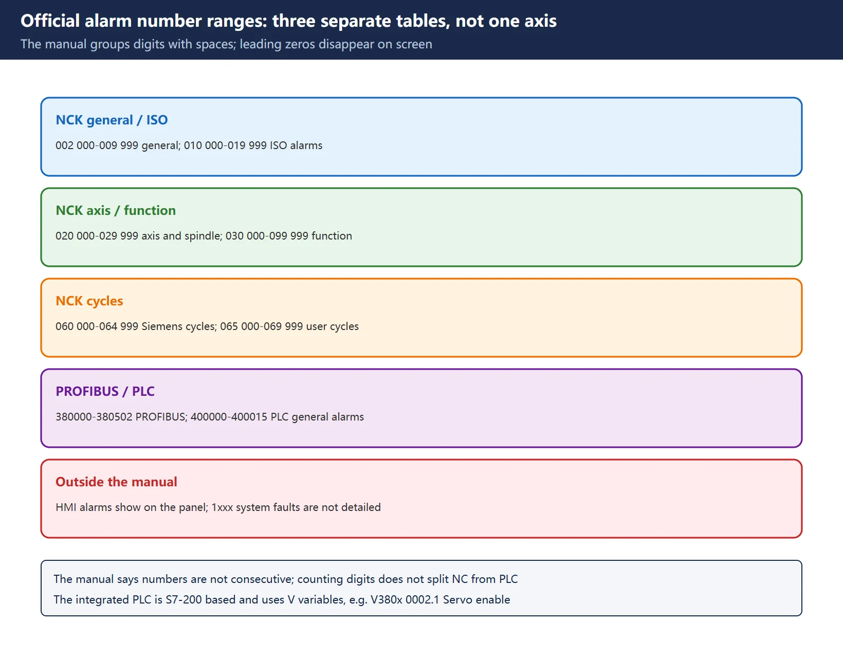
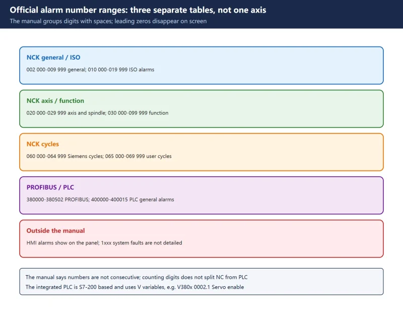
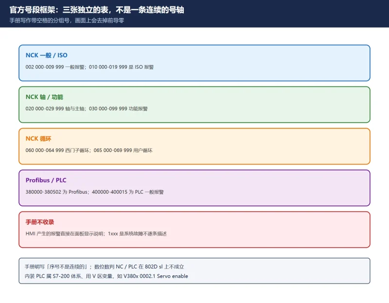
The official manual gives three separate tables under “alarm number ranges”, not one continuous number axis:
| Source family | Range in the manual | Meaning |
|---|---|---|
| NCK | 002 000 - 009 999 | General alarms |
| NCK | 010 000 - 019 999 | ISO alarms |
| NCK | 020 000 - 029 999 | Axis / spindle alarms |
| NCK | 030 000 - 099 999 | Function alarms |
| NCK | 060 000 - 064 999 | Siemens cycle alarms |
| NCK | 065 000 - 069 999 | User cycle alarms |
| PROFIBUS | 380000 - 380502 | PROFIBUS alarms |
| PLC | 400000 - 400015 | PLC general alarms and messages |
Table 1 The three “alarm number range” tables in the 802D sl Diagnostics Manual (spaces reproduce the manual grouping; leading zeros are dropped on screen)
🚨 Three traps worth remembering:
- Leading zeros and digit counts mislead you. The manual writes the general NCK band as
002 000 - 009 999, but the screen shows four-digit numbers like2000,2001and2100; the020 000 - 029 999band shows five-digit numbers like25050. Counting digits does not tell you NC from PLC on an 802D sl — you have to see which table the number falls into. - The manual explicitly says the numbers are not consecutive and that alarms are listed in ascending number order within each chapter. Gaps inside a range are normal; a missing hit in a searchable copy does not prove the number does not exist.
- The manual covers only NCK, PROFIBUS, cycles and PLC. It states that other alarms originating from the HMI are displayed directly on the operator panel with their explanation and are therefore not listed, and that questions about the integrated PLC should refer to the SIMATIC S7-200 documentation. That last sentence explains a major difference from 840D sl: the 802D sl integrated PLC is S7-200 based and uses V-area variables, so copying 828D or 840D DB block numbers into an 802D sl job looks in the wrong place. One example from the manual is the NC/PLC interface signal
V380x 0002.1(Servo enable).
One widespread claim also needs correcting: several third-party “802D sl alarm number allocation” charts call 0-9999 NCK general and 10000-19999 NCK channel, then list large PLC bands such as 200000-299999. Those charts do not match the official tables above and are not used here. For the six-digit 840D sl ranges see SINUMERIK 840D sl Alarm List; for cross-brand number formats see CNC Alarm Number Formats by Brand.
2. The 700000 User Alarm Family
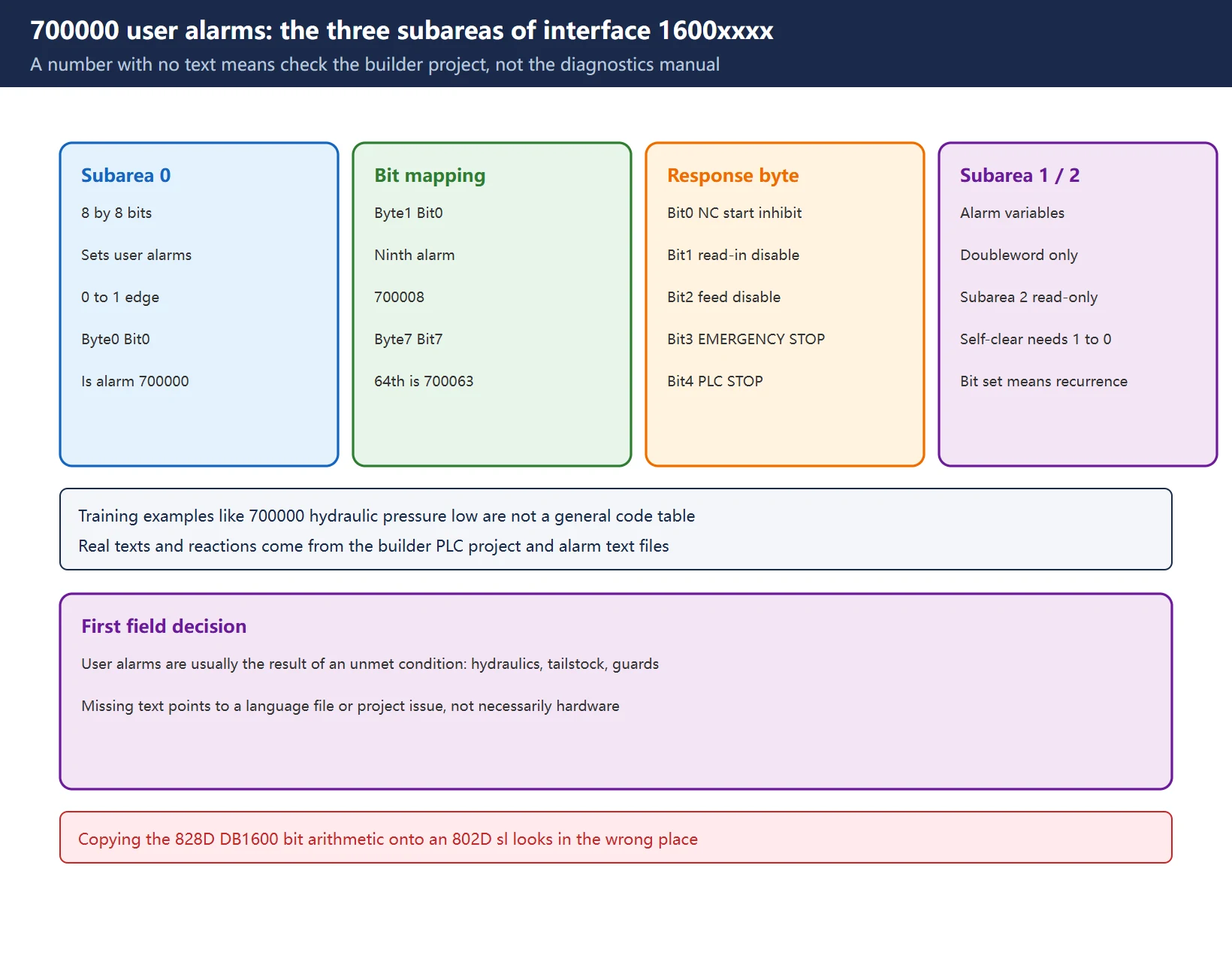
The structure given in the 802D sl manual section “PLC alarms / User alarms” is the key to understanding why a screen can show a number with no text:
- The user interface
1600xxxxprovides subareas0,1and2. Subarea 0 is 8 by 8 bits used to set user alarms on a0 to 1edge: Byte 0 Bit 0 is the first user alarm700000, Byte 1 Bit 0 is the ninth (700008), and Byte 7 Bit 7 is the 64th (700063). - The response byte (Byte 0) is defined as: Bit 0 = NC start inhibited, Bit 1 = read-in disable, Bit 2 = feed disable for all axes, Bit 3 = EMERGENCY STOP, Bit 4 = PLC STOP. Subarea 2 is read-only and lets the user evaluate which alarm responses are active.
- Subarea 1 holds alarm variables and additional information and can only be read or written as a doubleword. Self-clearing user alarms must be cancelled by the user with a
1 to 0edge on the bit in subarea 0; other alarms are cleared by the PLC once it detects the cancel condition, and will immediately recur if the triggering bit is still present. - Training material shows example texts such as
700000hydraulic pressure low,700001tailstock not in position and700002axis in parked position, together with an “alarm number to PLC signal bit to NC machine data14516[index]” relationship. Those are training examples, not a general code table: the real texts and reactions are defined by the machine builder in the PLC project and the alarm text files, so consult the project documentation supplied with the machine.
Table 2 The three user interface subareas and their roles (exact bit numbers and responses depend on the machine builder project)
So when the HMI shows only a 7000xx number with no message text, first suspect a missing or inconsistent alarm text or language file in the machine builder project rather than searching the Siemens Diagnostics Manual — user-defined texts are deliberately outside that manual. For the equivalent bit arithmetic on 828D see SINUMERIK 828D User Alarm Bits and 828D Extended User Alarms 701000-701999; for the 840D DB2 conversion see SINUMERIK 828D Cycle Alarms.
3. Alarm 25050 Contour Monitoring: A Fully Verifiable Entry
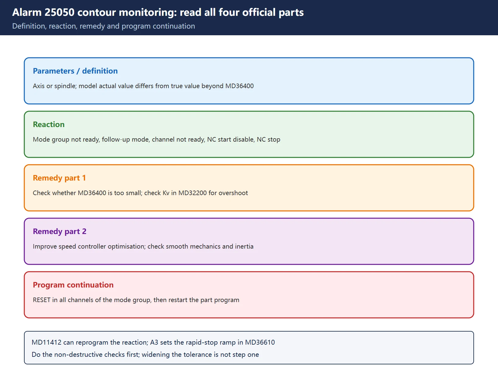
25050 is the one entry in this family worth memorising in full, and the Diagnostics Manual and Function Manual A3 chapter agree on it:
| Part | Official content summary |
|---|---|
| Parameters | %1 = axis name or spindle number |
| Definition | The NCK calculates, for each interpolation point (setpoint), the actual value that should result from an internal model. If it differs from the true machine actual value by more than the tolerance in MD36400 $MA_CONTOUR_TOL, the program is aborted and the alarm is issued |
| Reaction | Mode group not ready; NC switches to follow-up mode; channel not ready; NC start disable in this channel; interface signals are set; alarm display; NC stop on alarm |
| Remedy | Check whether the tolerance in MD36400 is too small; check position loop optimisation (Kv factor in MD32200 $MA_POSCTRL_GAIN) for overshoot; improve speed controller optimisation; check smooth running of the mechanics and inertial masses |
| Program continuation | Clear the alarm with the RESET key in all channels of the mode group, then restart the part program |
Table 3 Five key parts of alarm 25050, summarised from the official entry rather than reproduced verbatim
Function Manual Axis Monitoring (A3) adds three points that matter on the shop floor:
- Contour monitoring is active for axes and position-controlled spindles. On excessive deviation the axis or spindle is stopped via a speed setpoint ramp with rapid stop and an open position control loop; the braking ramp time is set in
MD36610 AX_EMERGENCY_STOP_TIME. Other axes in the same interpolation are also stopped with following error reduction. - The alarm reaction can be reprogrammed.
MD11412 $MN_ALARM_REACTION_CHAN_NOREADYcan change the reaction of “channel not ready” alarms, so the same number can bring a machine to a slightly different state on different machines. - A3 lists a whole family of monitoring functions: contour, position, standstill, clamping, speed setpoint, actual velocity, encoder, static limits, limit switch and working area limitation. The neighbouring entry
25060speed setpoint limitation refers toMD36210 $MA_CTRLOUT_LIMITandMD36220 $MA_CTRLOUT_LIMIT_TIME; position monitoring toMD36020 POSITIONING_TIME,MD36010 STOP_LIMIT_FINEandMD36000 STOP_LIMIT_COARSE; standstill monitoring toMD36030 STANDSTILL_POS_TOLandMD36040 STANDSTILL_DELAY_TIME. These numbers come from official manual entries, but every value must be checked against the local machine data and the supplied manual — never copy settings from another machine.
For the tuning workflow see 828D/840D Following Error and Contour Error Tuning; for cycle alarm number bands see 828D Cycle Alarms 61000 / 62000 / 65xxx.
4. Alarm Reactions and Delete Conditions
The manual devotes Chapter 3 (list of action codes) and Chapter 4 (system response to alarms, including 4.1 alarm deletion criteria) to explaining the reaction lines inside each alarm entry. The reaction line is as important as the remedy, because it decides whether you can simply reset or need a power cycle:
| Reaction term | What it means in the shop |
|---|---|
| Mode group / channel not ready | That mode group or channel no longer accepts a start |
| NC switches to follow-up mode | The position loop no longer follows the setpoint; actual position follows the measured value |
| NC start disable in this channel | A reset alone will not allow a start; the condition must be cleared |
| Interface signals are set | NC/PLC interface bits are set and can be traced from the PLC side |
| NC stop on alarm | Motion stops immediately; do not try to bypass it with a dry run |
| Alarm display | Indication only, usually without a change in operating state |
Table 4 Common reaction terms in the Diagnostics Manual and their field meaning
Two more short-number groups from the same manual show why a number range is not the same as fault ownership:
2000“PLC sign-of-life monitoring”: the PLC must regularly send a sign of life or the alarm appears. The remedy explicitly says this alarm occurs when the PLC is stopped, listing a programming tool stopping the PLC, a commissioning switch stopping the PLC and an alarm stopping the PLC. Program continuation is power off / power on.2001“PLC not started” means the PLC did not send at least one sign of life within the specified time after power-on. The 828D principle is covered in SINUMERIK 828D Alarm 2000/2001.2100/2101/2102are the three NCK battery states.2100is the warning limit (the manual gives a 2.7-2.9 V prewarning threshold and notes a nominal 3.0-3.1 V at 950 mAh, with replacement required within six weeks);2101is undervoltage detected during operation, where the manual states that data is not lost if the battery is changed without interrupting the power supply, and that the NCK buffer capacitor holds the supply for at least 30 minutes;2102is undervoltage detected during power-up, where the reaction escalates to NC not ready, follow-up mode, channel not ready, NC start disable and NC stop on alarm. The 828D procedure is in 828D NCK Battery Alarm 2100/2101/2102. ⚠️ Voltage thresholds and battery replacement procedures are version dependent — follow the manual and machine builder instructions for your own control.
Finally, alarms numbered 1xxx are system faults. The manual states they are not described individually and asks you to collect the alarm number, alarm text and the internal system fault number contained in the text before contacting technical support. Looking those numbers up in a per-alarm explanation table is a dead end.
5. Combined Alarms: Find the First Cause
When a single fault raises several numbers, working through them one by one from the top is the least efficient approach. A steadier sequence:
- Group the visible alarms by number range: NCK general / axis / cycle, PROFIBUS, PLC, user alarm, system fault. Numbers from different families usually mean one root cause plus several knock-on reactions.
- Read the reaction lines to find the upstream one. Alarms carrying EMERGENCY STOP, PLC STOP, read-in disable or NC start inhibit are often the precondition for the others; user alarms (
700000upward) are usually the result of an unmet machine builder condition such as hydraulics, tailstock, magazine or guards. - Look at timing and stage within one family. Battery alarms
2100then2101or2102are stages of one root cause; contour monitoring25050often appears next to speed setpoint limitation alarms, in which case check mechanics and drives before widening a tolerance band. - Do the non-destructive checks first: the
%1parameter in the alarm text, interface signals, PLC condition bits, diagnostic screens, then machine data. - Archive before changing MDs: record the original values, software version, full alarm text and the moment it appeared. Widening a tolerance such as
MD36400can hide a real mechanical or drive problem, so keep it as a last step after the cause is confirmed.
🚨 Some circulating lists of “combined chains” with per-number explanations and causal links could not be verified against a reliable official source, so this page neither reproduces nor infers them. For combined alarms we give the reading method only; look up each individual number using the keys in the next section.
6. Five-Step Field Check and Manual Lookup Keys
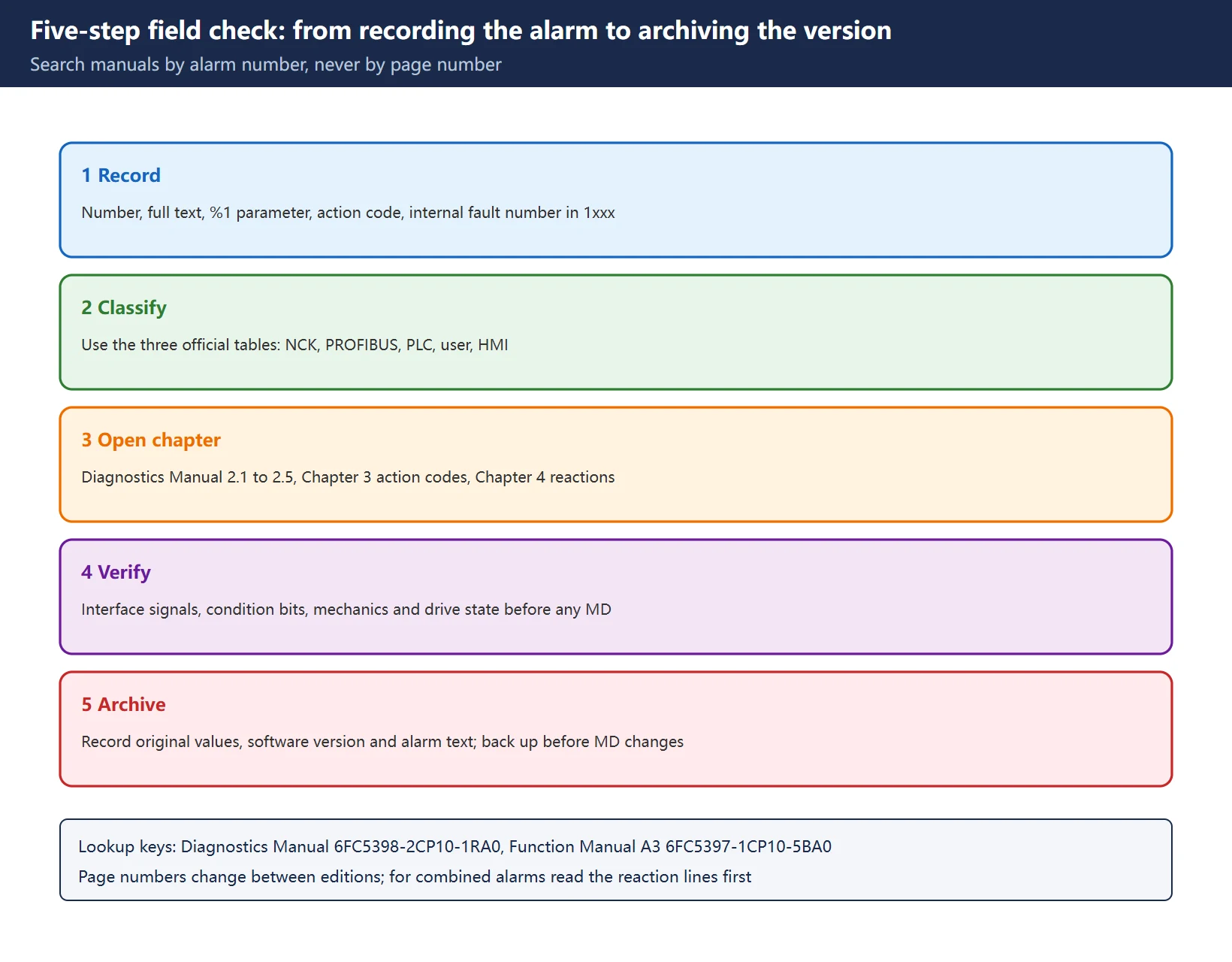
| Step | Action | Typical mistake |
|---|---|---|
| 1 Record | Copy the number, full text, %1 parameter, action code and the internal fault number in 1xxx alarms | Copying only a number and losing the context |
| 2 Classify | Use Table 1 to decide NCK / PROFIBUS / PLC / user / HMI / system fault | Judging by digit count or leading zeros |
| 3 Open the chapter | Diagnostics Manual 2.1 NCK and ISO, 2.2 cycles, 2.3 PROFIBUS, 2.4 PLC, 2.5 SINAMICS parameters; Chapter 3 action codes; Chapter 4 system response and 4.1 deletion criteria; Annex A abbreviations; Index I | Using an 828D or 840D manual for an 802D sl |
| 4 Verify | Non-destructive checks first: interface signals, condition bits, mechanical and drive state, software version | Widening a tolerance band before the cause is known |
| 5 Archive | Record full alarm text, range, reaction, remedy, original MD values and version; back up before MD changes | Writing only “reset done” and having nothing to work with next time |
Table 5 The five field checks and the typical mistake at each step
Official lookup keys (search by alarm number, not by page number):
- *SINUMERIK 802D sl Diagnostics Manual*, software version 1.4, order number
6FC5398-2CP10-1RA0(an 06/2009 English Diagnostics Manual also exists) — number range tables, per-alarm four-part descriptions, action codes, system reactions and alarm deletion criteria. - *SINUMERIK 802D sl Function Manual*, Turning / Milling / Nibbling, 11/2012,
6FC5397-1CP10-5BA0— search Axis Monitoring (A3) and Contour monitoring for the monitoring principle and related machine data. - *SINUMERIK 802D sl manual*, section “11.3 PLC alarms / 11.3.2 User alarms” (05/2005,
6FC5397-0CP10-1BA0) — the1600xxxxuser alarm interface and response bits. - Search the official documentation library with “alarm number plus entry number plus filename stem”; page numbers change between editions, so searching the number beats turning pages. Obtain manuals through the Siemens Industry Support portal; this page offers no third-party download.
- For the data recovery sequence see 828D NCK Battery Alarm context; for cross-brand number formats see CNC Alarm Number Formats by Brand; for the 840D sl manual chapter map see SINUMERIK 840D sl Alarm Code Quick Reference.
7. Scope and compliance
This page provides only officially verifiable number range frameworks, reaction terminology, interface structures and lookup paths, plus one fully verifiable summary of the 25050 entry. Per-alarm manual text, alarm text tables, page numbers, the complete action code table and machine builder alarm texts are not reproduced, inferred or invented here. No manual download, file mirror, archive bundle or third-party mirror is provided, because these documents vary greatly by edition and reproducing them is both unreliable and a licensing issue. Order numbers and chapter numbers appear purely as lookup keys; check them against the software version printed on the cover of the documentation supplied with your machine. Machine data values, range boundaries and screen labels vary with the software version and machine builder project; anything uncertain is explicitly marked as needing on-site verification.
8. Related pages on this site
- Number ranges: CNC Alarm Number Formats by Brand · SINUMERIK 840D sl Alarm List · 840D sl Alarm Code Quick Reference
- Monitoring and reactions: 828D/840D Contour and Following Error Tuning · 828D Cycle Alarms 61000/62000/65xxx · 828D Alarm 2000/2001 · 828D NCK Battery Alarm 2100/2101/2102
- User alarms: 828D User Alarm Bits DB1600 · 828D Extended User Alarms 701000-701999 · 840D sl Safety Integrated Alarms
Frequently Asked Questions
Can 802D sl alarms really be split into “five digits NC, six digits PLC”?
No. The official Diagnostics Manual writes the NCK bands as 002 000 - 009 999, 010 000 - 019 999, 020 000 - 029 999 and so on; with leading zeros removed, the screen shows both four-digit numbers like 2000 and five-digit numbers like 25050. The 400000 band is PLC general alarms and the 380000 band is PROFIBUS alarms. More importantly, 2000 and 2001, two PLC sign-of-life alarms, sit in the NCK alarm section themselves. Compare each number against the three official range tables instead.
The screen shows only a 7000xx number with no alarm text. Is the control faulty?
Usually it is not a hardware fault. On an 802D sl, numbers from 700000 are machine builder user alarms whose texts come from the PLC project and its alarm text files; the Siemens Diagnostics Manual does not include them and only defines the 1600xxxx interface bit mapping and response byte. When a text or language file is missing or inconsistent, the HMI may show the number alone, but the triggering condition (hydraulics, tailstock, guards, magazine and so on) is normally still real. Check the project documentation supplied with the machine and the PLC condition bits, not a generic alarm code table.
For 25050 contour monitoring, is widening MD36400 the right first move?
Not as a first step. The official entry lists “check whether the tolerance in MD36400 is too small” among the remedies, but in the same breath asks you to check the Kv factor in MD32200, speed controller optimisation and smooth mechanical running. Widening the tolerance band can hide mechanical binding, poor lubrication, excessive acceleration or a drive-side problem. Use the reaction line to understand the stop, perform non-destructive checks (interface signals, mechanics, drive state), and only then decide on an adjustment — recording the original value and taking a backup first.
Last updated: 2026-11-11
Where to go next
- FANUC Troubleshooting — the full guide library: alarms, diagnosis numbers, servo, spindle, PMC and electrical faults, organised by symptom.
- CNC Repair Tools — which instrument measures what: multimeters, clamp meters, insulation testers and oscilloscopes, with the specification that actually matters.
- Remote Technical Support — have the readings reviewed with you: alarm reverse lookup, PMC ladder analysis and servo tuning advice by call. Repair companies and integrators welcome.
Read the guide, get the right instrument, or walk the diagnosis through with someone — pick whichever you need.
The original Chinese version — same procedure, with the full field notes.




















暂无评论内容