


🚨 Scope and compliance: number ranges, code families and diagnostic-number practice are summarised from the public chapters of the FANUC servo amplifier maintenance manual, CNC maintenance manual and parameter manual shipped with the machine. Three existing pages on this site cover the three systems separately: Fanuc servo amplifier 7-segment codes, the Fanuc servo load meter and the SINUMERIK alarm list for comparison. Manual text and code tables are copyright protected: this page explains the relationship between the three systems, how to cross-check against your own manuals and the troubleshooting order. It reproduces no code-table screenshots and offers no manual download link, file mirror or archive. Alarm text, diagnostic numbers and display characters vary with the control series (0i / 30i / 31i), amplifier generation (alpha SVU / alpha i SVM / beta i) and software version, so always use the manuals shipped with your machine.
30-Second Triage: Which Code System Are You Looking At
Table 0 Six field clues and their first stop
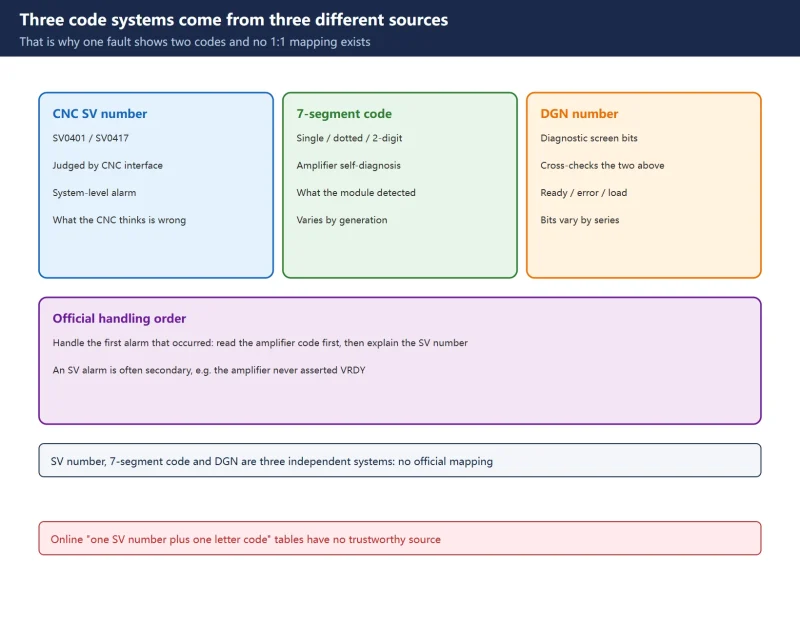
Three Code Systems: Why One Fault Shows Two Codes
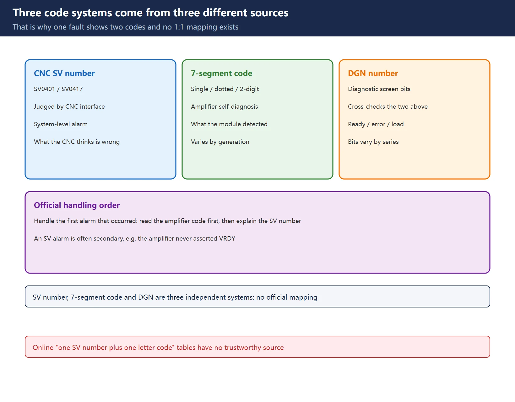
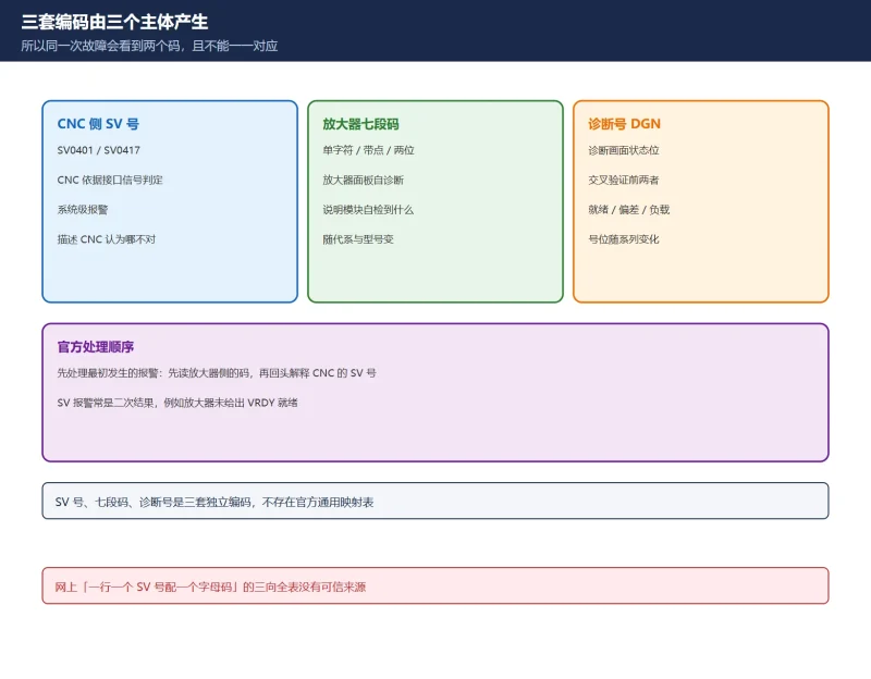
The three systems are produced by three different devices, so they cannot be merged and there is no one-to-one correspondence:
- CNC-side SV alarm: a system-level alarm raised by the CNC from the axis control card, FSSB and interface signals, written as
SVplus a number (for exampleSV0401). It describes what the CNC believes is wrong. - Amplifier seven-segment code: a self-diagnosis character shown on the servo or spindle amplifier’s own display, describing what that module itself detected.
- Diagnostic number (DGN): status bits and values on the CNC diagnosis screen, used to cross-check the evidence behind the first two, such as ready signals, position error and load current.
Seeing two codes for one fault usually means the CNC-side alarm is a secondary result. For example, if the amplifier does not assert servo ready for some reason, the CNC reports SV0401 while the amplifier shows its own code. The official order is to treat the first alarm that occurred first: read the amplifier-side code, then interpret the CNC SV number.
| Code | Reported by | Typical form | Portable across models? |
|---|---|---|---|
| SV alarm | CNC | SV0401 SV0417 | Ranges broadly shared, text varies by series |
| Amplifier seven-segment | Servo / spindle amplifier | Single character, dotted code, two digits | No, varies by generation and module |
| Diagnostic number | CNC diagnosis screen | DGN number plus bits / values | Bit layout varies by series and configuration |
Table 1 Origin and portability of the three code systems
CNC SV Numbers: Ranges and Official Sample Rows
SV alarms come in functional families; the on-site searchable list is in our servo alarm code table SV0301-SV0441. The rows below are samples whose official wording is consistent across independent sources and does not depend on the amplifier generation, included to demonstrate how to read one row:
| SV number | Official alarm name | First field action |
|---|---|---|
SV0401 | Servo ready signal (VRDY) off | Check the power chain first: control supply, E-stop released, MCC and breaker, terminator connector, then read the amplifier code |
SV0404 | VRDY signal stuck on | Check amplifier and wiring, do not change parameters first |
SV0410 | Excess position error at stop | Check mechanical bind, gravity-axis brake and servo gain |
SV0411 | Excess position error in motion | Check overload, encoder feedback and amplifier |
SV0417 | Illegal digital servo parameter | Restore servo initialisation parameters from backup, verify motor ID and flexible gear ratio |
SV0436 | Soft thermal (OVC) | Check cooling, load and duty cycle, not a power-module swap |
Table 2 Six verifiable SV number samples (not a per-number full table)
🚨 A conflict worth calling out: some online tables describe SV0401 as “amplifier overheat” or “servo amplifier overload”, while the FANUC wording is servo ready signal (VRDY) off, a “not ready” condition rather than an overheat. When even one number’s meaning is wrong, a “one SV number plus one display character per row” universal three-way table has no credible source. This page does not provide one and does not recommend copying one. The “full three-way table” suggested in the brief is deliberately reduced here to a relationship framework, official samples and a cross-check method.
Amplifier Seven-Segment Codes: Single, Two-Digit and Dotted
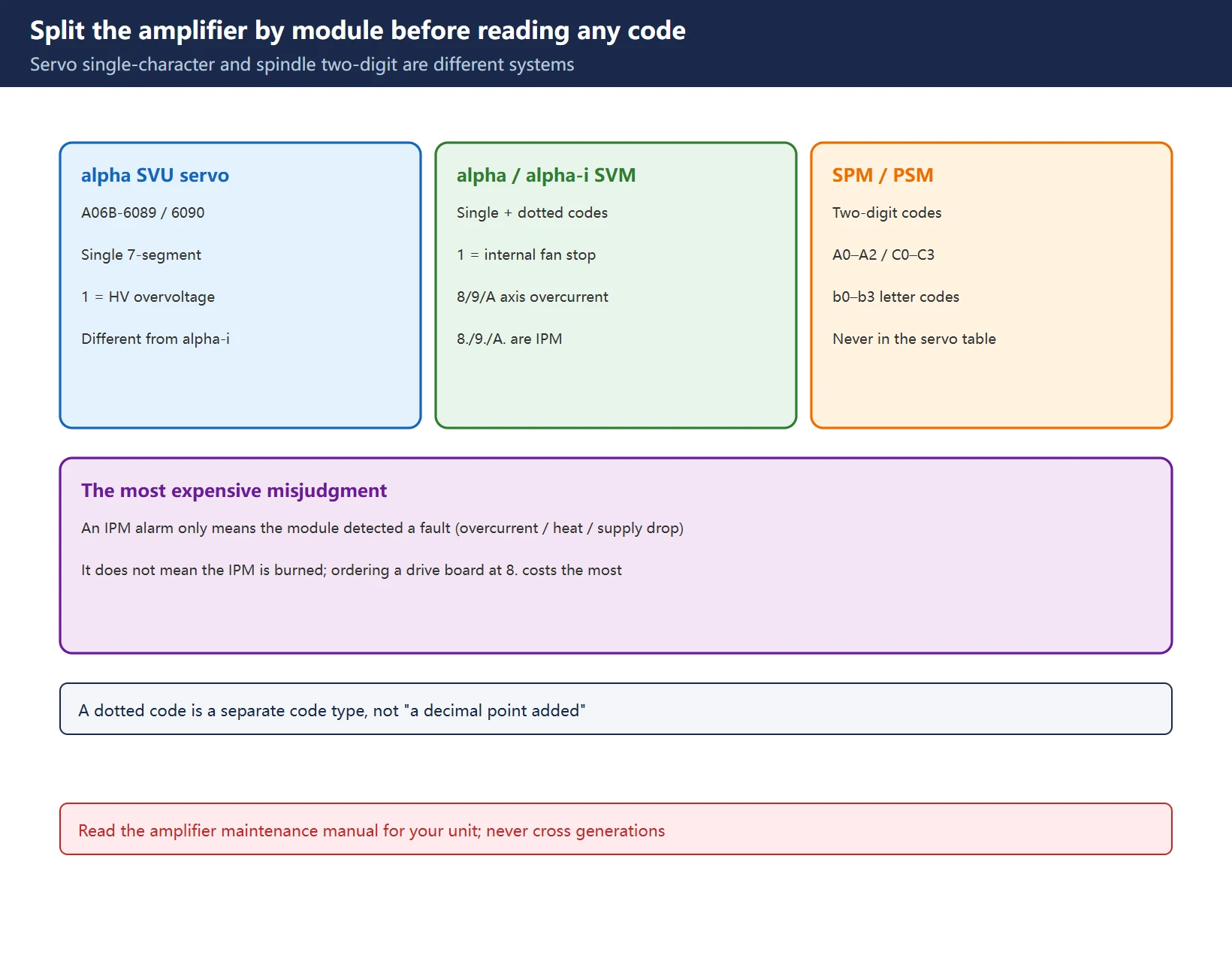
Identify the module first; this is where most mistakes start:
| Module | Display | Examples with an official basis | Caution |
|---|---|---|---|
| alpha SVU (A06B-6089 / 6090 etc.) servo amplifier | Single seven-segment character | 1 relates to HV overvoltage | Different meaning from alpha i generation |
| alpha / alpha i SVM servo amplifier | Single seven-segment character | 1 relates to an internal fan stop; 8 / 9 / A to L / M / N axis overcurrent; 8. / 9. / A. to the matching axis IPM alarm | A dotted code is a separate code, not a decimal point |
| SPM / PSM spindle amplifier, integrated units | Two digits | Letter codes such as A0–A2, C0–C3, b0–b3 | Never mix into the servo single-character table |
Table 3 Three display families and their boundaries
One more common misreading: an IPM alarm only means the intelligent power module detected an abnormality; its detection covers overcurrent, overtemperature and a drop in its own control supply. It does not mean the IPM has definitely failed. Ordering a replacement drive board the moment you see 8. is one of the most expensive mistakes on site. See our A06B seven-segment code guide for the per-character detail.
Diagnostic Numbers: Why No Universal Cross-Reference Exists
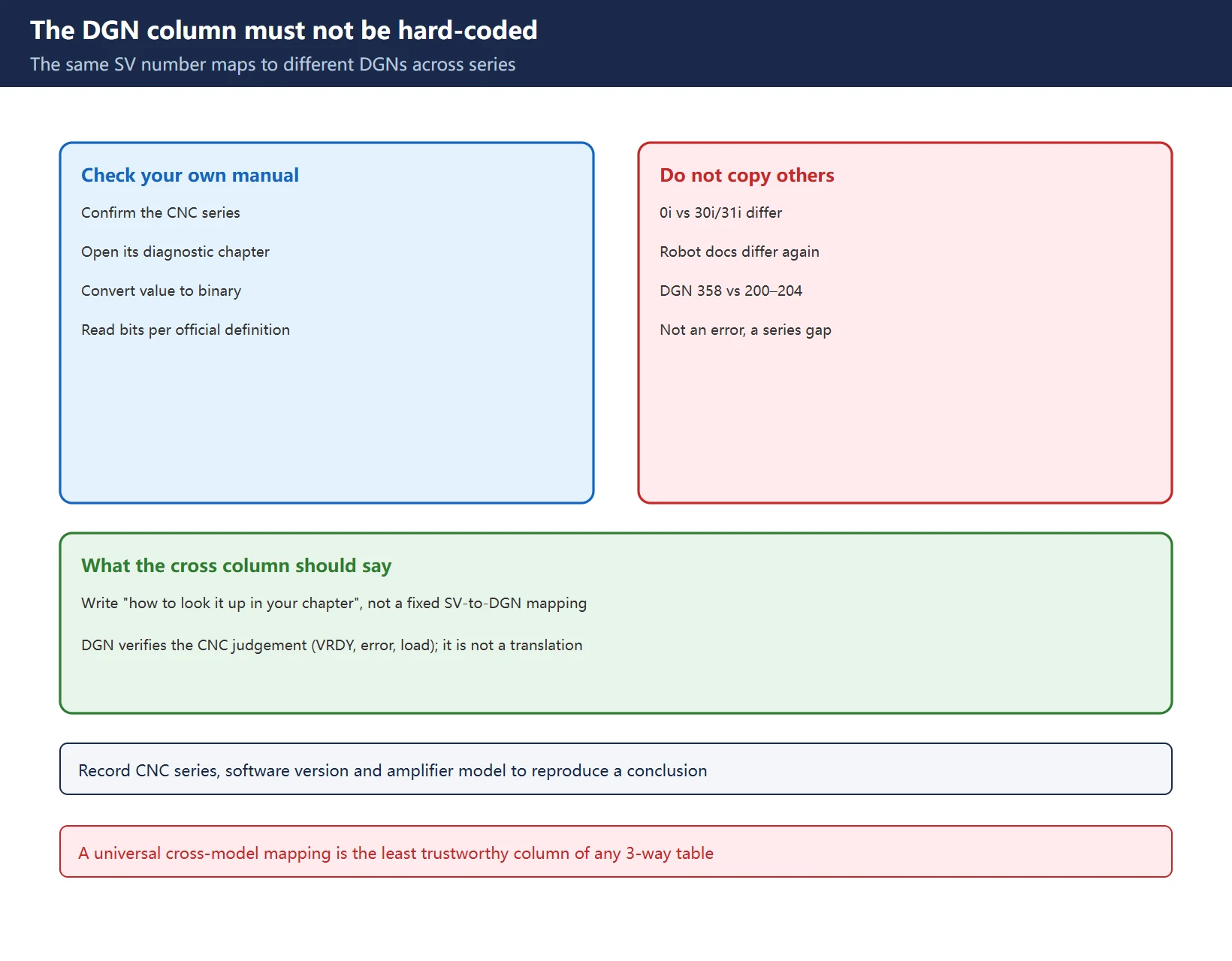
The diagnostic number is the column that should never be hard-coded. One verifiable example: field material for SV0401 points to DGN 358 (convert to binary to locate the fault, common in robot and specific-series documents), while other material points to 200–204 (servo load and position-error class, see our servo load meter guide). Neither is wrong; the control series and configuration differ.
| What the column should say | Correct practice | What not to do |
|---|---|---|
| Diagnostic number | Look it up in the diagnosis chapter of the manual for your control series | Do not reuse a table from another series |
| Bit meaning | Convert the value to binary and read each bit against the official definition | Do not guess that a bit means “ready” |
| Relation to the SV number | Use it to verify the CNC's evidence (VRDY, error, load) | Do not treat it as a translation of the SV number |
| Version differences | Record control series, software version and amplifier model | Do not publish one universal mapping |
Table 4 Four constraints on the diagnostic-number cross-reference column
Action Column: What to Check, What to Replace
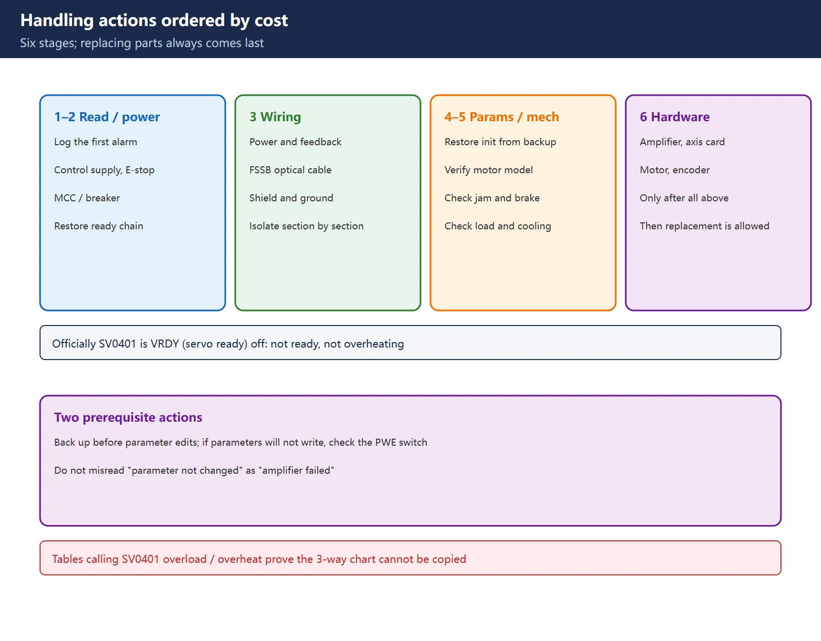
The value of a three-way table ends in “what next”. Ordering actions by cost avoids swapping boards first:
| Stage | Check | Typical action | Replace parts? |
|---|---|---|---|
| 1 Read everything | Full CNC alarm text, amplifier code, diagnostic bits | Record the alarm that occurred first | No |
| 2 Power chain | Control supply, E-stop, MCC, breaker, terminator | Restore supply and the ready chain | No |
| 3 Wiring | Motor power, feedback, FSSB optics, shield grounding | Reseat, measure, isolate section by section | No |
| 4 Parameters | Servo initialisation, motor ID, flexible gear ratio | Restore from backup and verify | No |
| 5 Mechanics | Bind, brake, load, cooling | Remove external load factors | No |
| 6 Hardware | Amplifier, axis card, motor, encoder | Only after all of the above | Yes, only now |
Table 5 Six action stages and the replacement threshold
Take a recoverable backup before changing parameters, and read the CNC-side parameter write protection basics before assuming an amplifier fault when a parameter simply will not write.
Official Manual Lookup and Version Checks
| Search key | Where to read it | Purpose |
|---|---|---|
| Control series and software version | System screen / version display | Determines SV text and the diagnosis chapter |
| Amplifier model | A06B-xxxx nameplate | Determines seven-segment character meanings |
| SV alarm number | Full text on the CNC alarm screen | Full-text search in the maintenance manual |
| Display character | Actual panel display (including a dot) | Search in the amplifier maintenance manual |
| Diagnostic number | Diagnosis screen | Cross-check against that series' bit definitions |
Table 6 Five official search keys and where to read them
Manual text and complete code tables are copyright protected; this page reproduces none and offers no download link, file mirror or archive. For number-by-number lookup, use the manuals shipped with your machine. Our PLC basic program guide FB1 / FB2 / OB100 covers a different layer (PLC project structure) and should not be confused with amplifier self-diagnosis.
Three Core Articles and Related Pages
Table 7 Further reading for each face of the three code systems
Frequently Asked Questions
How do I map a FANUC SV alarm code to the amplifier 7-segment display?
There is no official general mapping, and you should not try to build one. The SV number is a system-level alarm the CNC derives from interface signals, while the display character is the amplifier’s own self-diagnosis. They come from different devices and vary with control series and amplifier generation. Record the full CNC alarm text and the actual panel character (including any dot) separately, look each up in the matching manual for your machine, cross-check with diagnostic numbers, and treat the first alarm that occurred as the root cause.
What does a dotted 7-segment code like 8. mean on a Fanuc servo amplifier?
A dotted code is a distinct code type, not “an 8 with a decimal point”. On alpha / alpha i SVM units, 8 / 9 / A relate to L / M / N axis overcurrent while 8. / 9. / A. relate to the matching axis IPM alarm. But an IPM alarm only means the intelligent power module detected an abnormality (overcurrent, overtemperature or a drop in its own control supply): it does not prove the IPM has failed. Rule out external causes per your amplifier maintenance manual before deciding to replace it. Spindle amplifiers use a two-digit code system, so this rule does not apply there.
Which diagnostic number shows why SV0401 appeared?
It depends on the control series and configuration; there is no single answer. Field material points to DGN 358 converted to binary in some series and robot documentation, while 200–204 style servo status and load diagnostics are used for 0i-series cross-checking. Use the diagnosis chapter of the manual shipped with your machine, convert the value to binary and read each bit against the official definition. Do not copy a table from another series.
Last updated: 2026-11-11
Where to go next
- FANUC Troubleshooting — the full guide library: alarms, diagnosis numbers, servo, spindle, PMC and electrical faults, organised by symptom.
- CNC Repair Tools — which instrument measures what: multimeters, clamp meters, insulation testers and oscilloscopes, with the specification that actually matters.
- Remote Technical Support — have the readings reviewed with you: alarm reverse lookup, PMC ladder analysis and servo tuning advice by call. Repair companies and integrators welcome.
Read the guide, get the right instrument, or walk the diagnosis through with someone — pick whichever you need.
The original Chinese version — same procedure, with the full field notes.















暂无评论内容