


Scope and compliance: the alarm meanings, related parameter numbers and diagnostic mappings on this page come from public Fanuc maintenance-manual and alarm-list content (0i-D/0i-F and Series 30i alarm lists, and the 16i/18i/21i-B appendix alarm list). The same alarm number can carry different meanings and different related parameters on different control generations; every row is tagged with its source generation, and you must confirm against your own machine’s manual before acting. The circulating claim “PS0242 maps to parameter 2002#4” could not be traced to any official source and is not adopted. No manual text is reproduced and no downloads are offered – only retrieval method and framework.
30-second summary: how the three directions work
| Your situation | Direction to use | Landing point |
|---|---|---|
| Alarm on, want to know which parameter to touch | Alarm to parameter | Table 2 / Table 3 / Table 4 |
| Alarm on, want the live machine reading | Alarm to diagnostic | Table 2 / Table 5 |
| About to edit a parameter, afraid of tripping or masking an alarm | Parameter back to alarm | Read Table 2 backwards |
| Alarm not in the manual at all | Check whether it is machine-builder defined | See the four-step triage |
Table 0: Four entry points of the three-way lookup
On-site companions: Fanuc Servo Alarm Three-Way Table: SV Number, Seven-Segment Code, Diagnostic, Fanuc Parameter Number Band Map, Fanuc Diagnostic Number (DGN) Reference, and Hidden Faults You Can Catch Only Through Diagnostics.
1. The three-way relationship: alarm is the symptom, parameter is the configuration, diagnostic is the live reading
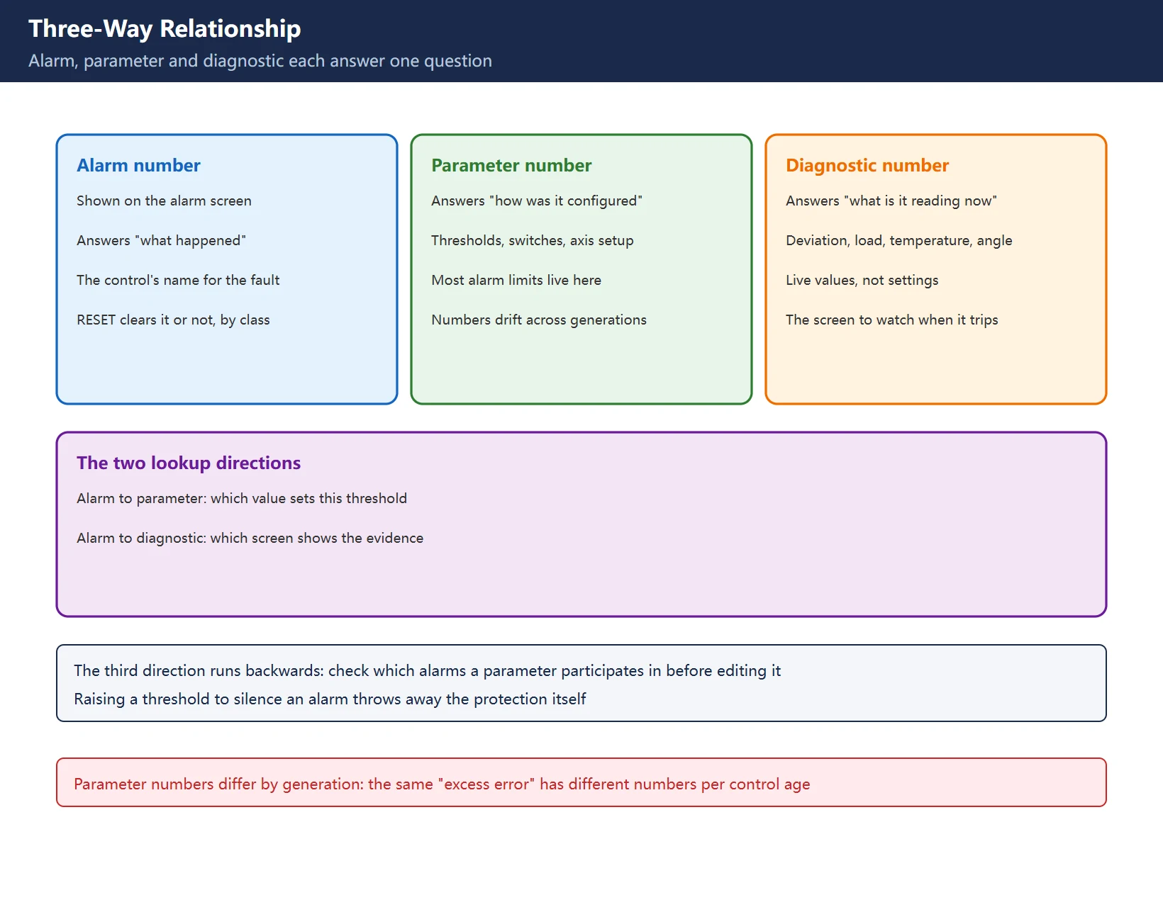
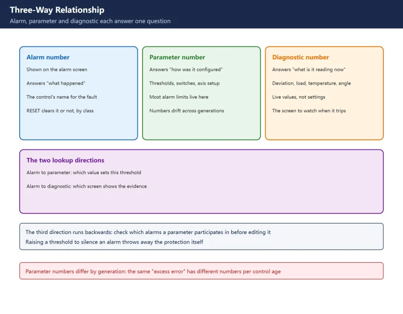
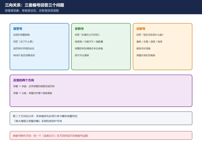
Each numbering system answers one question. The alarm number says what happened: it is the control’s name for an abnormality, shown on the alarm screen; whether RESET clears it depends on the alarm class. The parameter number says how this machine was configured: thresholds, function switches and axis setup all live in parameters, and most alarm limits are read from them. The diagnostic number says what the machine measures right now: position deviation, load, temperature, one-revolution signal angle.
That gives two natural lookup directions: alarm to parameter (which parameter sets this alarm’s threshold) and alarm to diagnostic (which screen to watch when it trips). The third direction runs backwards: before editing a parameter, check which alarms it participates in – then you know both what a wrong value will trigger, and what protection you are giving up if you silence an alarm by raising its limit.
One caution up front: parameter numbers drift across generations. The same “excess error” condition is limited by different parameter numbers on different generations (next section), and copying an online “alarm-to-parameter” table without checking the generation is the number-one way this lookup goes wrong.
2. Two numbering generations: identify your machine first
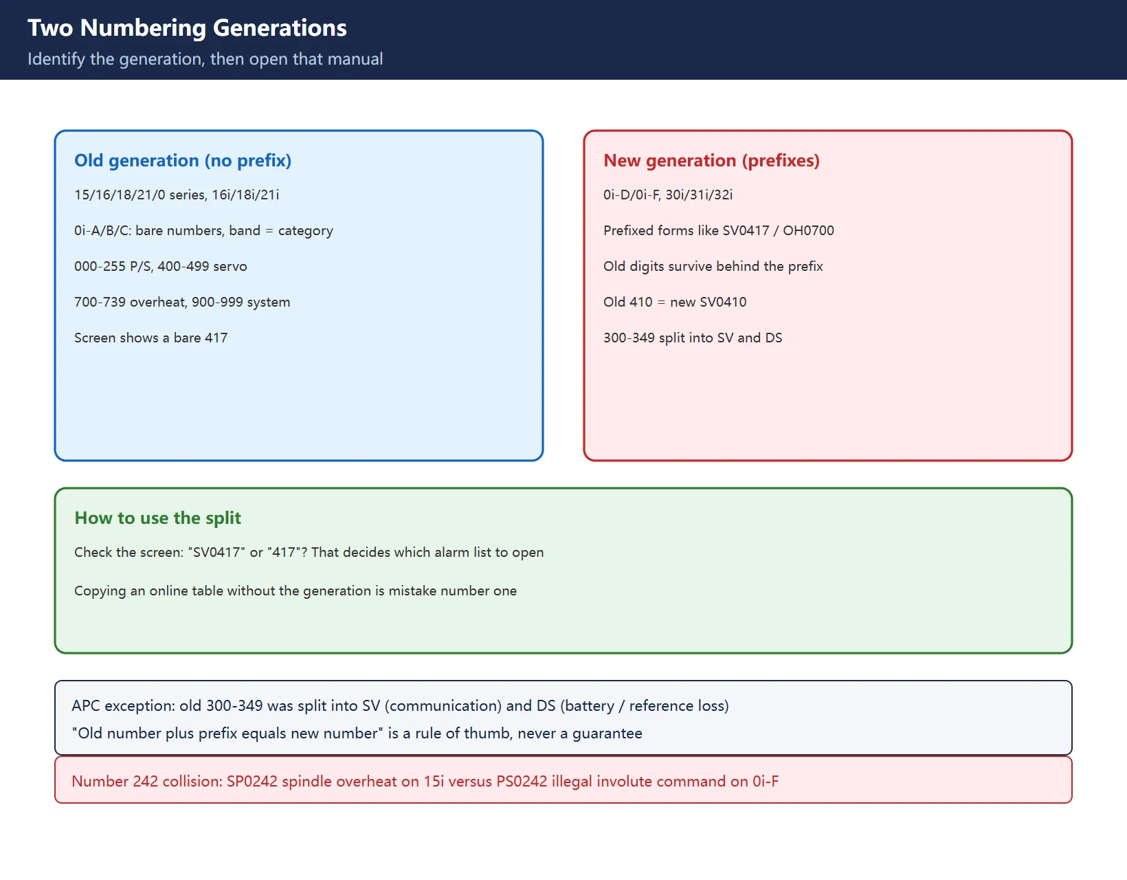
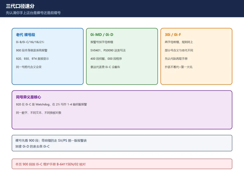
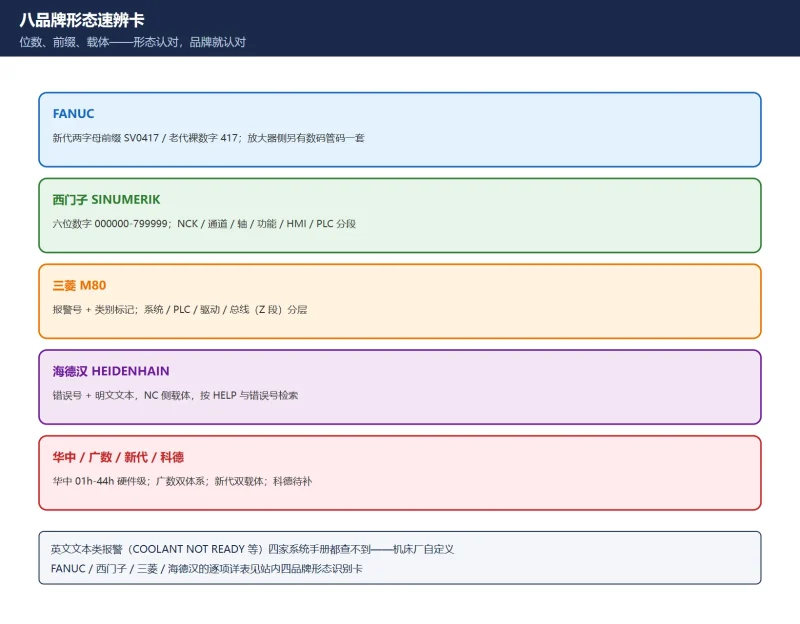
Fanuc alarm numbering exists in two forms. The old generation (15/16/18/21/0 series, 16i/18i/21i, 0i-A/B/C) has no two-letter prefix – the number band itself is the category. The new generation (0i-D/0i-F, 30i/31i/32i) adds a two-letter prefix, and in most cases the old number survives behind it: old 410 = new SV0410, old 700 = new OH0700.
| Old number band | Category | New prefix |
|---|---|---|
| 000-255 (and part of 5000+) | Program / parameter (P/S) | PS (shown as BP/S when raised during background editing) |
| 300-349 | Absolute pulse coder (APC) | Split into SV (communication class) and DS (battery / reference-loss class) |
| 350-399 | Serial pulse coder (SPC) | SV |
| 400-499 | Servo | SV |
| 500-599 | Overtravel | OT |
| 700-739 | Overheat | OH |
| 740-748 | Rigid tapping | SP |
| 749-799 | Spindle | SP |
| 900-999 | System level | System alarm screen |
Table 1: Old number bands versus new prefixes (16i/18i/21i-B operator’s manual appendix)
How to use it: look at the alarm screen – is it “SV0417” or a bare “417”? That tells you which generation you are on, and which generation’s manual to open. See also the 900-band system alarm list (0i-MF/0i-MD flavour) as the companion entry point.
3. The SV band: alarm to parameter to diagnostic
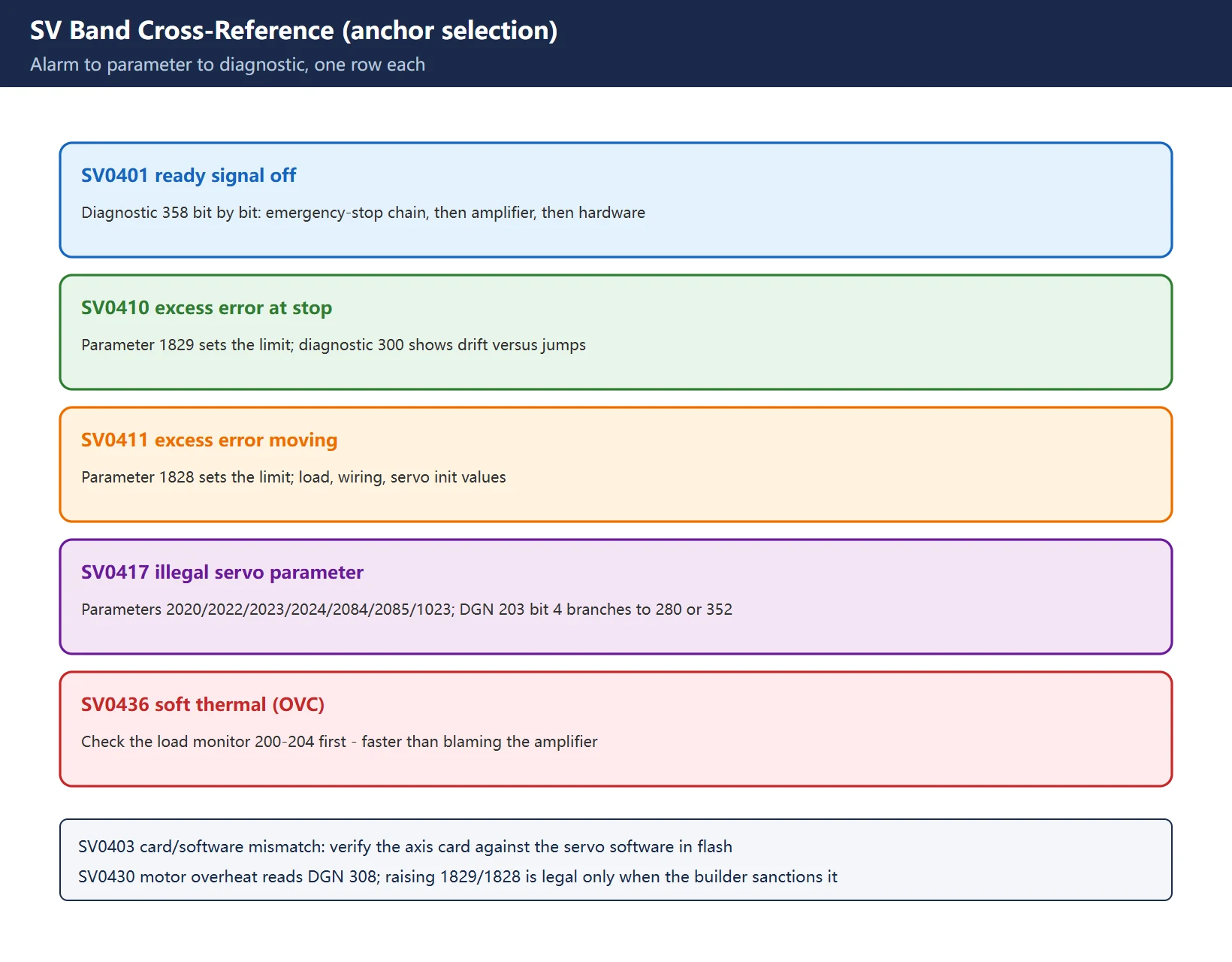
This table is the core of the page. Every row’s mapping is tagged with its source generation; rows without parameters mean the official alarm list does not associate one, so you work downwards from the diagnostic reading instead.
Table 2: SV-band three-way anchors (0i-D/0i-F and Series 30i alarm lists; parameter numbers must be checked per generation)
Three field notes belong in the text, not the table. First, SV0417 officially branches on diagnostic 203 bit 4: at 0 the CNC software detected the illegal parameter (work through the list in diagnostic 280), at 1 the servo software did (match the value in diagnostic 352 against the maintenance-manual table) – far cheaper than re-initializing everything. Second, raising 1829/1828 to silence SV0410/SV0411 is legitimate only when the machine builder sanctions it: raising a detection limit does not fix a sagging vertical axis or a slipping coupling, it converts an alarm into scrap. Third, SV0436 pairs with the load monitor: checking 200-204 to find which axis is overworking is faster than blaming the amplifier. The servo load monitor guide continues this thread.
4. The PS / PW band: program and parameter anchors
| Alarm | Meaning | Related parameters / setting | Handling |
|---|---|---|---|
| PS0090 | Reference position not established | 1815 bit4 (APZ, absolute zero set), 1815 bit5 (APC, absolute coder in use), 1006 bit5 (reference return required at power-on), 1850 (grid shift), 1005 bit0 / 1006 bit1 (method and direction) | After battery loss or coder swap: restore battery supply, move the axis to the reference mark, set APZ = 1, power-cycle as required |
| PS0100 | Parameter write-enable is ON (advisory) | PWE on the setting screen | Advisory: return PWE to 0 after editing and the alarm clears |
| PW0000 | A power-off-required parameter was changed | — | Power-cycle as instructed; RESET is not a substitute |
| PS0242 (0i-F/30i-B) | Illegal command in G02.2/G03.2 involute interpolation | — | Fix the block: start radius, base circle, sign and decimal point – a programming error, not a machine fault |
Table 3: PS / PW band anchors (0090/0100 flavour-confirmation against the machine manual required)
A same-number-different-meaning warning belongs here: alarm 242 on the Series 15i is SP0242 OVERHEAT (spindle overheat through speed-fluctuation detection, tied to the G26 detection parameters; the official handling is to reduce heavy cutting, check the tool and suspect the spindle amplifier), while on 0i-F/30i-B it is PS0242 (illegal involute interpolation command). One number, two generations, zero overlap in meaning – which is exactly why this page insists on identifying the generation before anything else. The claim “PS0242 maps to 2002#4” could not be traced to an official source and is not adopted.
5. The OH band and spindle-orientation anchors
| Alarm | Meaning | First checks |
|---|---|---|
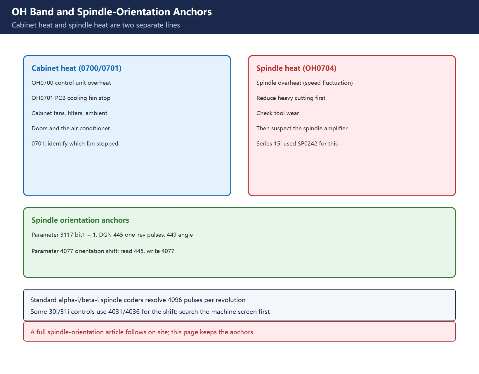
| OH0700 | Control unit overheat (cabinet / unit temperature over limit) | Cabinet fans, filters, ambient temperature, doors and air conditioner |
| OH0701 | Cooling fan motor stop (PCB / unit fan) | Identify which fan: dead motor, blocked rotor, connector and supply |
| OH0704 | Spindle overheat (spindle speed fluctuation detection) | Reduce heavy cutting first; check tool wear; suspect the spindle amplifier |
Table 4: OH band anchors (new generation; the old generation shows bare 700/701/704)
The OH lookup separates two lines: 0700/0701 are ventilation problems, 0704 is a spindle-and-load problem – do not mix them. Note also that the spindle speed-fluctuation overheat carries number SP0242 on the Series 15i: the same cause, a different number.
Spindle orientation gets its own anchors (full article to follow): with parameter 3117 bit1 set, diagnostic 445 shows the pulse data from the one-revolution signal and 449 shows the angle from it; parameter 4077 holds the orientation stop position shift – the standard routine being M19, release, hand-turn the spindle to the target position, read 445 and write it into 4077. The standard Fanuc alpha-i/beta-i spindle coder resolves 4096 pulses per revolution; some 30i/31i controls use a different orientation-shift parameter (4031/4036) – search the machine’s own parameter screen before touching anything.
6. The diagnostic reverse-lookup table
Table 5: Diagnostic reverse lookup (the counterpart of Tables 2-4)
On-site companions: the diagnostic number reference grouped by function, hidden faults caught through diagnostics for readings that trip no alarm at all (DGN000/003/005 and friends), and the four-step reverse lookup for builder-defined alarms when the text is the machine builder’s own.
7. How to run this lookup correctly – and its limits
The correct order is four steps: identify the generation (prefix or bare number), open that manual (that edition’s alarm list and parameter list), follow the table (the Related Parameters column in the alarm entry is the officially given third column), back up before editing (record the original value and return PWE to 0 afterwards).
Four limits, symmetrically: first, this page lists verified anchors only – it is not the full table, and anything not listed must be looked up in the shipped maintenance manual for your generation, not in a circulating “complete list”. Second, parameter numbers drift between generations; every number here is tagged, so copy the generation along with the number. Third, “alarm maps to parameter” is an influence relationship, not “edit this parameter and the alarm goes away” – clearing an alarm means clearing its cause, and a threshold only decides where the protection line sits. Fourth, machine-builder alarms (peripheral 1000 band, English-text messages) are not in the Fanuc manual at all: those go through the builder’s electrical drawings and ladder, per the builder-alarm reverse lookup.
Frequently Asked Questions
How do I find the parameter behind a Fanuc alarm number? Can I trust online tables?
Identify the generation first (two-letter prefix or bare number), then open the official maintenance-manual alarm list for that generation – the Related Parameters column is the officially sanctioned mapping. The problem with circulating tables is that they splice several generations into one sheet, so you can easily pick a parameter from the wrong generation. Every row here is generation-tagged for traceability; your own machine’s manual remains the final authority.
Is an old-style alarm “410” the same as the new “SV0410”?
In most cases the old number survives behind the prefix (410 to SV0410) and both the meaning (excess error at stop) and the related parameter (1829) carry over. The APC band is the standing exception: the old 300-349 band was split into SV (communication class) and DS (battery / reference-loss class) in the new generation. So “old number plus prefix equals new number” is a rule of thumb, never a guarantee – generation first, always.
Is the circulating advice “PS0242 means editing parameter 2002#4” reliable?
Not adopted. Number 242 is itself a cross-generation collision: on the 15i it is SP0242 spindle overheat (speed-fluctuation detection), on 0i-F/30i-B it is PS0242 illegal involute-interpolation command – two meanings with zero overlap. The “2002#4” mapping could not be traced to any official source. Confirm the control model first, then work from that machine’s own alarm list.
Last updated: 2026-11-16
Where to go next
- FANUC Troubleshooting — the full guide library: alarms, diagnosis numbers, servo, spindle, PMC and electrical faults, organised by symptom.
- CNC Repair Tools — which instrument measures what: multimeters, clamp meters, insulation testers and oscilloscopes, with the specification that actually matters.
- Remote Technical Support — have the readings reviewed with you: alarm reverse lookup, PMC ladder analysis and servo tuning advice by call. Repair companies and integrators welcome.
Read the guide, get the right instrument, or walk the diagnosis through with someone — pick whichever you need.
The original Chinese version — same procedure, with the full field notes.
















暂无评论内容