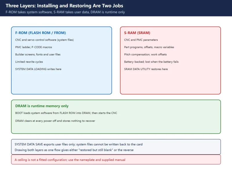



🚨 Scope and compliance: The BOOT main menu items, the split between system files and user files, the FAT16 card limit and the power-on key combinations come from Fanuc BOOT SYSTEM documentation and published 0i-series textbooks and course material. The definitions of
SV0368,SV0369andSV0403come from published Fanuc alarm lists and maintenance manual entries of theB-65285EN/04family. The eight-stepDGSERVO/DG2SERVOloading procedure, legacy key combinations, filename and capacity advice, and the R-30iB 2 MB / 3 MB image warning all come from third-party service sites and repair forums; no Fanuc manual original was verified for those, so they are lookup leads only and not operating instructions. Menu items, file names and software editions differ between 0i, 16i, 30i and Power Mate i controls and between machine builders, so every item must be checked against the manual supplied with the machine, using its cover number and edition. Manual text, system files and menu screenshots are copyright material; this page reproduces none of it and offers no downloads, file mirrors, cloud drives or packaged archives of system software, manuals or backups. F-ROM writes, SRAM restores and full clears irreversibly overwrite builder data and must only be performed by qualified personnel following the builder’s written procedure with a prior read-only record. Work on live or stored-energy components requires lockout/tagout. This page is not a backup or modification instruction.
30-Second Triage: Four Kinds of “Blank Screen”
| Symptom | Layer | First action | What not to do first |
|---|---|---|---|
| No display, no fans, no contactor pull-in | Supply, unrelated to software | Measure input voltage, fuses, PSU and the E-stop chain | Do not enter BOOT or pick menu items at random |
| Display present but stuck at BOOT, FROM/SRAM module error, or “no system software” | Missing or corrupt system software in F-ROM | Take a read-only record, then run SYSTEM DATA CHECK to see what remains | Do not start with SYSTEM DATA DELETE |
| Normal screens, but parameters, programs and offsets lost or scrambled | S-RAM user data lost (battery, parity, full clear) | Confirm you hold an SRAM backup from this same control | Do not treat a data restore as a software reinstall |
| Servo alarm after an axis card or amplifier swap | Servo software / hardware mismatch | Read the exact alarm in the matching manual | Do not read SV0368 as “servo software not installed” |
Table 0. Four startup failures and the first discrimination line
Three clues split the phrase “reinstall the system” into supply, system software and user data. FANUC Data Backup and Recovery: ALL I/O vs BOOT SRAM covers the third layer, while How to Clear All Parameters on a Fanuc Control covers the power-on full clear that actually wipes that layer. These are not interchangeable articles.
1. Three Layers: F-ROM, S-RAM and DRAM Decide What Gets Installed
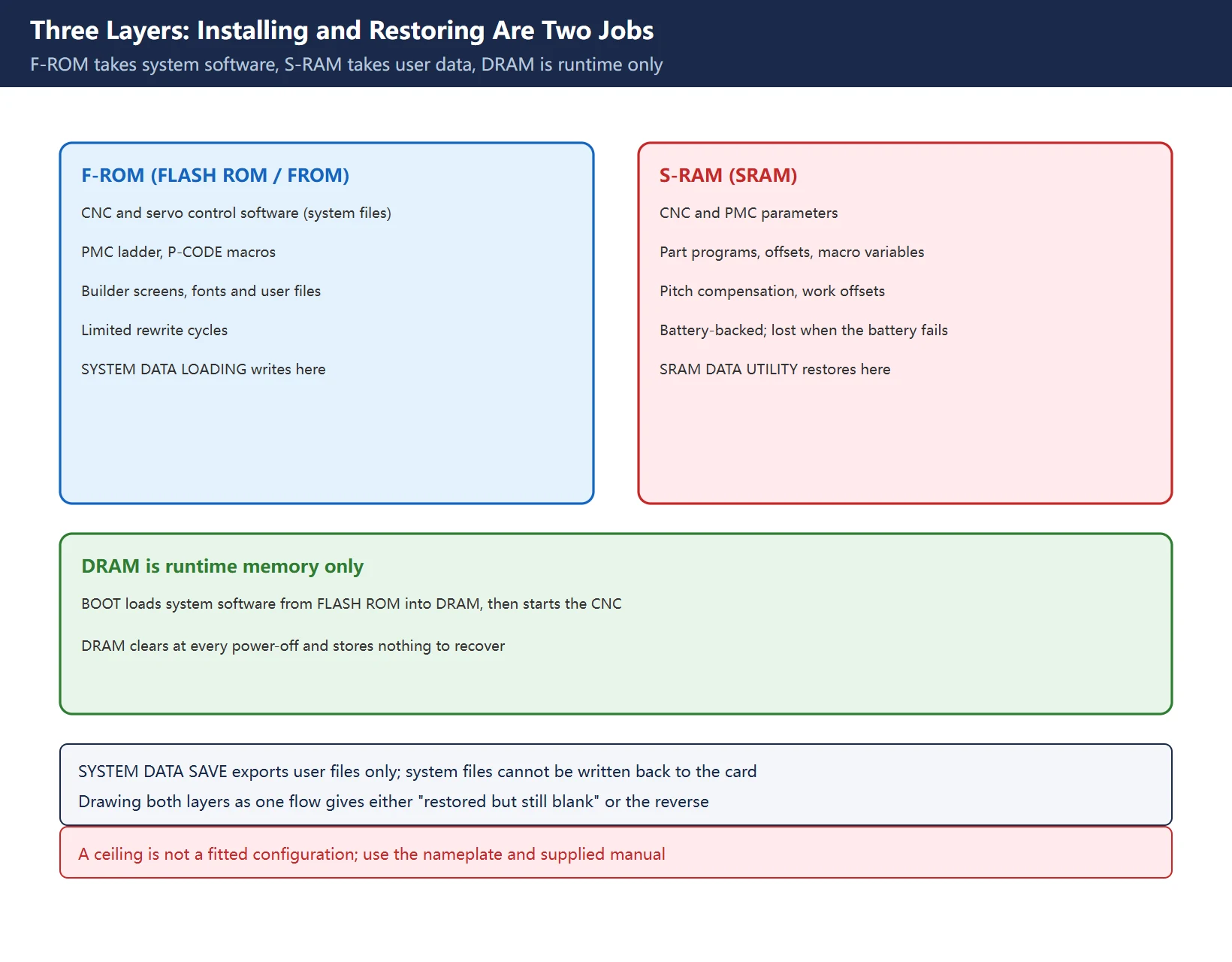
BOOT SYSTEM exists to load the system software from FLASH ROM into DRAM before the CNC software starts, and then start it. That gives three distinct layers.
| Layer | Contents | After power-off | Relevance here |
|---|---|---|---|
| DRAM | Operating system and working area loaded at runtime | Cleared, reloaded at every power-on | It stores nothing to recover, so “reinstall because DRAM failed” has no basis |
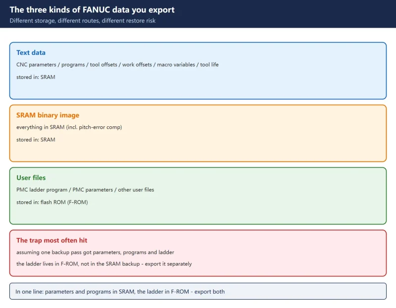
| F-ROM (FLASH ROM / FROM) | Fanuc-supplied CNC and servo control software (system files), builder PMC sequence programs, P-CODE macros, screens and fonts | Retained; limited rewrite cycles | This is what a real software install writes, via SYSTEM DATA LOADING / USER DATA LOADING |
| S-RAM (SRAM) | CNC and PMC parameters, pitch error compensation, part programs, tool offsets, macro variables, work offsets | Battery-backed; lost on battery failure or parity alarm | This is what a data restore recovers, via SRAM DATA UTILITY |
Table 1. Responsibility boundaries of the three memory layers
Two details are routinely missed. First, BOOT itself distinguishes system files from user files: system files are the Fanuc-supplied CNC and servo software, while user files are PMC ladder programs, P-CODE macros and builder-created content. SYSTEM DATA SAVE only writes user files to the card; system files cannot be saved back to the card. Second, SRAM DATA UTILITY handles the battery-backed area and will not replace servo software missing from F-ROM. Drawing both jobs as one flow produces the two opposite failures: “SRAM restored but still blank”, or “software installed but all parameters gone”.
2. The BOOT SYSTEM Main Menu: Two Paths, Not One
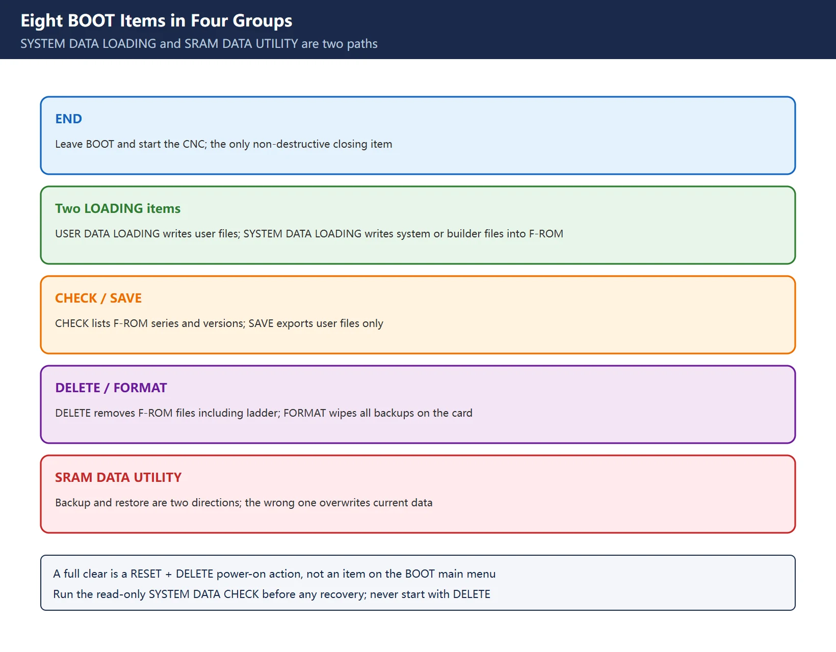
Published textbooks and course material list the 0i-series SYSTEM MONITOR MAIN MENU as follows (numbering may start at 1 or 10 and item counts differ by edition; use the screen on the machine).
| Item | Documented function | Layer | Consequence of a wrong selection |
|---|---|---|---|
END | Leave BOOT and start the CNC | none | none |
USER DATA LOADING | Write user data files from the card into F-ROM | F-ROM | Overwrites builder files |
SYSTEM DATA LOADING | Read system or builder files from the card and write them into F-ROM | F-ROM | Wrong edition or model can prevent startup |
SYSTEM DATA CHECK | List F-ROM files with series and version | read only | none; the right first step before any recovery |
SYSTEM DATA DELETE | Delete system or user files in F-ROM | F-ROM | Clears ladder programs as well |
SYSTEM DATA SAVE | Save user files from F-ROM to the card | export, read only | none, but system files are not saved |
SRAM DATA UTILITY | Back up S-RAM data to the card or restore it from the card | S-RAM | Wrong direction overwrites current data |
MEMORY CARD FORMAT | Format the memory card | card | Wipes all backups on the card |
Table 2. Eight BOOT items and what each one deletes
Circulating guides describe a single path, “System Data Loading, then SRAM Data Restore, choose file, confirm”. That path does not exist: SRAM BACKUP (CNC to MEMORY CARD) and RESTORE / SRAM RESTORE (MEMORY CARD to CNC) are two directions inside SRAM DATA UTILITY, whereas SYSTEM DATA LOADING only addresses F-ROM. A second common error is the warning “do not confuse Memory Clear with SRAM Restore in the menu”: a full clear uses a different power-on key action (RESET + DELETE), not a BOOT menu item. The genuinely destructive BOOT items are SYSTEM DATA DELETE and MEMORY CARD FORMAT. See How to Clear All Parameters on a Fanuc Control for the full-clear sequence.
3. Entering BOOT: Keys and Card Preconditions
| Item | Documented or circulated wording | Boundary |
|---|---|---|
| Common i-series entry | Hold the two rightmost soft keys below the screen while powering on, until SYSTEM MONITOR MAIN MENU appears | Must be held before the CNC starts; missing the window means a power cycle |
| Controls without soft keys | Hold MDI numeric keys 6 and 7 at power-on | Model dependent, check the supplied manual |
| Legacy 6M / 10M types | Third-party notes mention the numeric keypad - and . keys | Third-party wording, verify against the machine manual; do not try it on newer controls |
| 0i-MC / MD types | Third-party notes say E-stop must be pressed first because some builders fit a safety interlock | Third-party wording; never defeat a safety interlock |
| Card format | Fanuc BOOT documentation states files are read from a FAT16 card; FAT32 is not recognised | Large cards, exFAT and subfolders may make files invisible |
| Interface parameter | Textbooks set the memory-card I/O channel to 4 (0i-D material cites PRM020=4) | A parameter change: record it first and check the machine parameter list |
| File placement | Third-party material puts backup files in the root directory and warns about long names | Third-party wording, confirm on the actual screen |
| Card handling | Format only on first use or corruption; insert and remove with power off; never power down during a read or write | Distinguish from the destructive MEMORY CARD FORMAT |
Table 3. Entry methods and memory-card preconditions
The advice “file size must match the module capacity” has a real background, but its clearest source is a robot-controller image restore warning (see section 6), not a CNC SRAM restore rule. On CNC controls the common failure is a FAT16 card or a root-directory filename that BOOT cannot read, rather than the “1 MB backup into a 512 KB module crashes the control” story. Searching by manual type and section rather than page follows the same logic as CNC Alarm Number Formats by Brand: fix the numbering system before looking up an individual entry.
4. Three Numbering Systems Behind 368 / 369: SV0403 Is the Software Mismatch
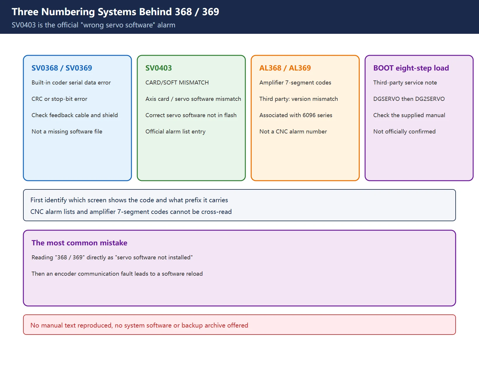
Briefing material treats “368 / 369 alarm” as simply “servo software missing or mismatched with the axis card”. That merges three unrelated numbering systems.
| Code | Documented meaning | Source level | Relation to a software install |
|---|---|---|---|
SV0368 | Serial data error (built-in pulse coder): communication data cannot be received | Fanuc alarm lists, B-65285EN/04 family maintenance manual entries | Check feedback cable, shielding and encoder, not a servo software reload |
SV0369 | Data transfer error (built-in): CRC or stop-bit error in pulse coder data | same | Same: noise and hardware direction |
SV0403 | CARD/SOFT MISMATCH: the axis card and servo software combination is incorrect; causes include a wrong axis card and the correct servo software not installed in flash memory | Fanuc alarm lists (0i-D and others) | This is the official “wrong servo software” alarm |
Amplifier AL368 / AL369 | Third-party compilation: seen on some 6096-series amplifiers after repair, linked to servo software and control board version mismatch | Third-party sites and forums | Amplifier-side codes, not CNC alarm numbers |
| “368 / 369 Alarm” in the BOOT loading note | Third-party T.I.E / fanucworld material: if these appear after fitting a drive, run the eight-step DGSERVO load | Third-party | A trigger description, not a Fanuc alarm manual entry |
Table 4. Three numbering systems and a fourth way of writing the same digits
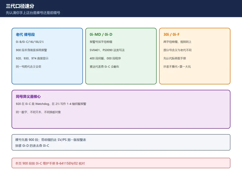
The first field check is therefore which screen the number appears on and what prefix it carries: SV0xxx on the CNC screen follows the servo alarm list, while a 7-segment code on the amplifier follows the amplifier manual. They cannot be cross-read. CNC Alarm Number Formats by Brand and Fanuc Servo Alarm Reference Chart give that “identify the numbering system first” framework; individual entries can then be checked in Fanuc Servo Amplifier Alarm Codes and the machine’s own alarm list.
5. DGSERVO / DG2SERVO in Eight Steps: Third-Party Wording Only
Several third-party service sites publish the same eight steps for loading servo software after replacing a fibre-optic servo module: hold the two rightmost soft keys at power-on to enter BOOT; insert the supplied SRAM card; choose SYSTEM DATA LOADING; select DGSERVO and confirm; wait for COMPLETE; choose END to return to the main menu; choose END again and boot the control; confirm; if 368 / 369 persists, repeat the load with DG2SERVO.
| Step | Published wording | Comment here |
|---|---|---|
| 1 | Hold the two right soft keys at power-on | Matches the general entry method in section 3 |
| 2 | Insert the SRAM card supplied with the module | Card file name and version must match this control |
| 3 | SYSTEM DATA LOADING | F-ROM layer, not an SRAM restore |
| 4 | Select DGSERVO, confirm | File name is third-party wording |
| 5 | Wait for COMPLETE | Power loss mid-write is high risk |
| 6-8 | Two END selections, boot the CNC, confirm | Recheck whether the alarm cleared |
| Fallback | Load DG2SERVO if still present | Explicitly stated in the third-party material |
Table 5. The third-party eight-step flow and its limits
The value of this flow is that it shows servo software really is a separate file set in F-ROM. It is, however, a service company’s field note, not a Fanuc alarm manual entry. This page gives no filename-to-version mapping and no source for software packages; which file and which series version to load can only be taken from the supplied manual and the builder’s written list. That is the same class of boundary as Why Is a Fanuc Parameter Missing?: a visible entry on a screen is not evidence that it is the right file for this machine.
6. Two Product Lines That Must Not Be Mixed: R-30iB Image Upgrade vs CNC BOOT
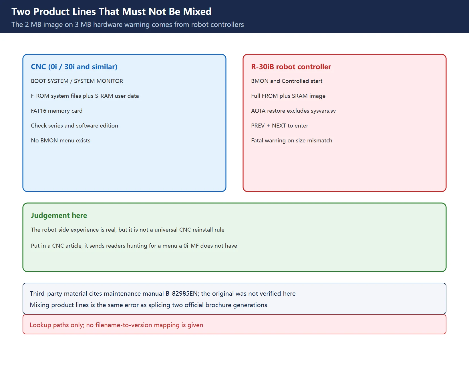
Briefing material presents “a 2 MB image on 3 MB hardware causes fatal damage; reload core software from BMON and exclude sysvars.sv during AOTA restore” as a fatal prerequisite for reinstalling a Fanuc CNC. Verification shows this wording comes from R-30iB / R-30iB Plus robot controller FROM/SRAM memory-upgrade material and robot forums. BMON, PREV + NEXT, AOTA (All Options Together Application), sysvars.sv and image files such as FROM00.IMG / SRAM02.IMG are robot-controller terms, not BOOT SYSTEM menu items on 0i / 30i CNC controls.
| Dimension | CNC (0i / 30i and similar) | R-30iB robot controller |
|---|---|---|
| Boot environment | BOOT SYSTEM / SYSTEM MONITOR MAIN MENU | BMON, Controlled start and related menus |
| Restore object | F-ROM system files, S-RAM user data | Full controller image (FROM + SRAM), All of above file sets |
| Capacity warning | No official clause verified in this review | Third-party material quotes a restore-screen warning: mismatched FROM / SRAM size can cause fatal controller damage |
| Excluded file | No equivalent concept | Forums and third-party material require excluding sysvars.sv during AOTA restore after an upgrade |
| Official basis | Fanuc BOOT SYSTEM documentation and supplied maintenance manuals | Third-party material cites maintenance manual B-82985EN; the original was not verified here |
Table 6. Boundaries between the two product lines
This does not make the robot-side experience worthless; it means a robot image-restore warning cannot be promoted into a universal rule for reinstalling a CNC. Put into a CNC article, it sends readers looking for a BMON menu that does not exist on a 0i-MF. Likewise, “only same-size images restore safely” belongs to the robot manual. Mixing numbering and procedures across product lines is the same error identified in Fanuc CNC Specifications Comparison, where two generations of official brochure figures were spliced into one row.
7. Item-by-Item Recovery and Acceptance: One SRAM Restore Is Not Everything
Published descriptions of SRAM backup contents do not agree. Some list CNC parameters, PMC parameters, pitch compensation, part programs, tool offsets, macro variables and macro P-CODE variables; others say simply “parameters, programs and other user data”; one note warns that when the soft-key entry method shows no digits, the backup may exclude PMC parameters. The safer approach is two layers: run one overall SRAM restore, then check each screen for what is still missing.
| Item | Where to verify | Common omission |
|---|---|---|
| CNC parameters | Parameter screen versus exported parameter file | Power-on-effective parameters need a full power cycle |
| PMC parameters and ladder | PMC screens, ladder step count and version | Soft-key entry may exclude PMC parameters |
Part programs and the O9000 region | Program directory and program number protection | Macro programs and subprograms are often missed |
| Tool offsets, work offsets, macro variables | Offset screens and macro variable screen | Itemised exports are frequently incomplete |
| Pitch error compensation, reference point | Compensation screen and re-referencing | Absolute encoder machines need the manual's reference-point procedure |
| Servo software and system file versions | SYSTEM DATA CHECK and the alarm screen | Match to axis card and amplifier versions |
| Ladder running, axes moving | Low-speed dry run with no load | “It boots” alone misses this layer |
Table 7. Item-by-item verification and acceptance list
Third-party material also mentions absolute-encoder reference-point handling after a card restore; such parameter and bit numbers belong to “verify in the supplied manual” territory, so no setting values are given here. For read-only records and export methods see How to Export / Print FANUC Parameter Tables and Ladder Programs and How to Backup and Restore a Fanuc PMC Program from Ladder-III.
8. Official Lookup Paths and Site Index
Table 8. Six verification targets and official search keys
Searching by section and full alarm name rather than page number is the most useful habit in this documentation set, because page numbers move between languages and editions. No manual text is reproduced here and no third-party download is offered.
9. Site Index
Table 9. Eight further reading links
Frequently Asked Questions
How do I recover lost Fanuc system software, and how do I enter BOOT SYSTEM?
First decide whether F-ROM system software or S-RAM user data is missing; they use different menu items. A common i-series entry is to hold the two rightmost soft keys below the screen while powering on, or MDI numeric keys 6 and 7 on controls without soft keys, until SYSTEM MONITOR MAIN MENU appears; confirm the combination in the manual supplied with the machine. Once in, use the read-only SYSTEM DATA CHECK to see which F-ROM files and versions remain, then let qualified personnel decide whether SYSTEM DATA LOADING is needed based on the builder’s written list. Parameters and programs go through the restore direction of SRAM DATA UTILITY. Do not casually run SYSTEM DATA DELETE or MEMORY CARD FORMAT. See FANUC Data Backup and Recovery: ALL I/O vs BOOT SRAM.
What are Fanuc 368 / 369 alarms, and how is servo software reloaded?
Identify which screen shows the number. On the CNC, SV0368 is a built-in pulse coder serial data error and SV0369 a built-in data transfer CRC or stop-bit error; both are feedback-channel faults. The official alarm that corresponds to wrong servo software is SV0403 CARD/SOFT MISMATCH, whose stated causes include the correct servo software not being installed in flash memory. Amplifier 7-segment AL368 / AL369 are a separate code set that third-party compilations link to servo software and control board version mismatch. The eight-step DGSERVO, then DG2SERVO loading flow is a third-party field note, not an official alarm manual entry; this page offers it only as a lookup lead, with no software package or version mapping. Which file to load must come from the supplied manual and the builder’s written list.
What should I check about filenames and capacity when restoring from a memory card?
What is documented: Fanuc BOOT reads files from a FAT16 card and does not recognise FAT32; textbooks set the memory-card I/O channel accordingly (0i-D material cites PRM020=4); the card is formatted only on first use or after corruption; cards are inserted and removed with power off and power must not be cut during a read or write. Long filenames, root-directory placement, capacity matching and the “2 MB image on 3 MB hardware causes fatal damage” warning are third-party material, and the last one clearly belongs to the R-30iB robot-controller memory-upgrade scenario rather than CNC BOOT. Verify each against the control series, software edition and supplied manual; do not set parameters or overwrite data based on a single web article.
Last updated: 2026-11-15
Beyond the boot menu: real-machine disciplines a simulator does not cover
Beyond the boot menu: SV0403 card/software mismatch anchors
Where to go next
- FANUC Troubleshooting — the full guide library: alarms, diagnosis numbers, servo, spindle, PMC and electrical faults, organised by symptom.
- CNC Repair Tools — which instrument measures what: multimeters, clamp meters, insulation testers and oscilloscopes, with the specification that actually matters.
- Remote Technical Support — have the readings reviewed with you: alarm reverse lookup, PMC ladder analysis and servo tuning advice by call. Repair companies and integrators welcome.
Read the guide, get the right instrument, or walk the diagnosis through with someone — pick whichever you need.
The original Chinese version — same procedure, with the full field notes.
















暂无评论内容