


🚨 Scope and compliance: The
SV0434definition comes from FanucB-65325EN/01family beta-i maintenance material andB65515ENrelated entries. The thresholds, fault values, reactions and remedies for230041/230043come from the published SINAMICS S120 Diagnostic Manual entries (6FC5398-8BP40-0BA0, 07/2010 edition). The two conflicting readings ofPS0003come respectively from the MTT Fanuc alarm library and aggregator sites such as industrialpro and cncfixtech. No-load versus load separation, ripple screening with a multimeter AC range, segmented load isolation and 7-segment orCXA2Aterminal measurements are third-party service-site and field notes; no official manual original was verified for those, so they are diagnostic ideas, not operating instructions. The 5 V / 24 V voltage and ripple figures in the circulating checklist are field rules of thumb, not official acceptance criteria of any brand, and are labelled as such here. Alarm texts, thresholds and diagnostic parameters differ between drive families and software editions, so every item must be checked against the manual supplied with the machine, using its cover number and edition. Manual text and alarm tables are copyright material; this page reproduces none of it and offers no manual downloads, file mirrors, cloud drives or packaged archives. Cabinets contain live conductors and stored DC-link energy: all measurement must be performed by qualified personnel under lockout/tagout and the builder’s written procedure. This page is not a live-working instruction.
30-Second Triage: Suspect Power, but Read the Numbering First
| Symptom | First discrimination line | Which document | What not to do first |
|---|---|---|---|
| Alarms jump around, repeated restarts, unexplained hangs | Suspect 24 V ripple or momentary sag | Machine alarm list plus power schematic | Do not start editing parameters as a “logic fault” |
SV0434 on screen with an axis name | Amplifier internal control supply; detection point is the amplifier | Fanuc servo / amplifier maintenance manual | Do not chase only the motor and encoder |
230041 on screen | SINAMICS power-unit 24 V undervoltage; reaction NONE | SINAMICS S120 Diagnostic Manual | Do not look it up in a Fanuc alarm list |
PS0003 on screen | Confirm what this code means in this machine's alarm list | Machine alarm list | Do not read “PS” as Power Supply and swap the PSU |
| Same alarm after a PSU swap | Check load-point voltage drop and downstream shorts | Electrical schematic and terminal drawings | Do not keep resetting and retrying production |
Table 0. Five random-fault patterns and the first discrimination line
“Half of all random alarms are power problems” is a field judgement, not a statistic. The actionable first step is translating a symptom into a code plus a detection point, which is the framework in CNC Alarm Number Formats by Brand and Fanuc Servo Alarm Reference Chart.
1. Three Codes Are Not One Alarm
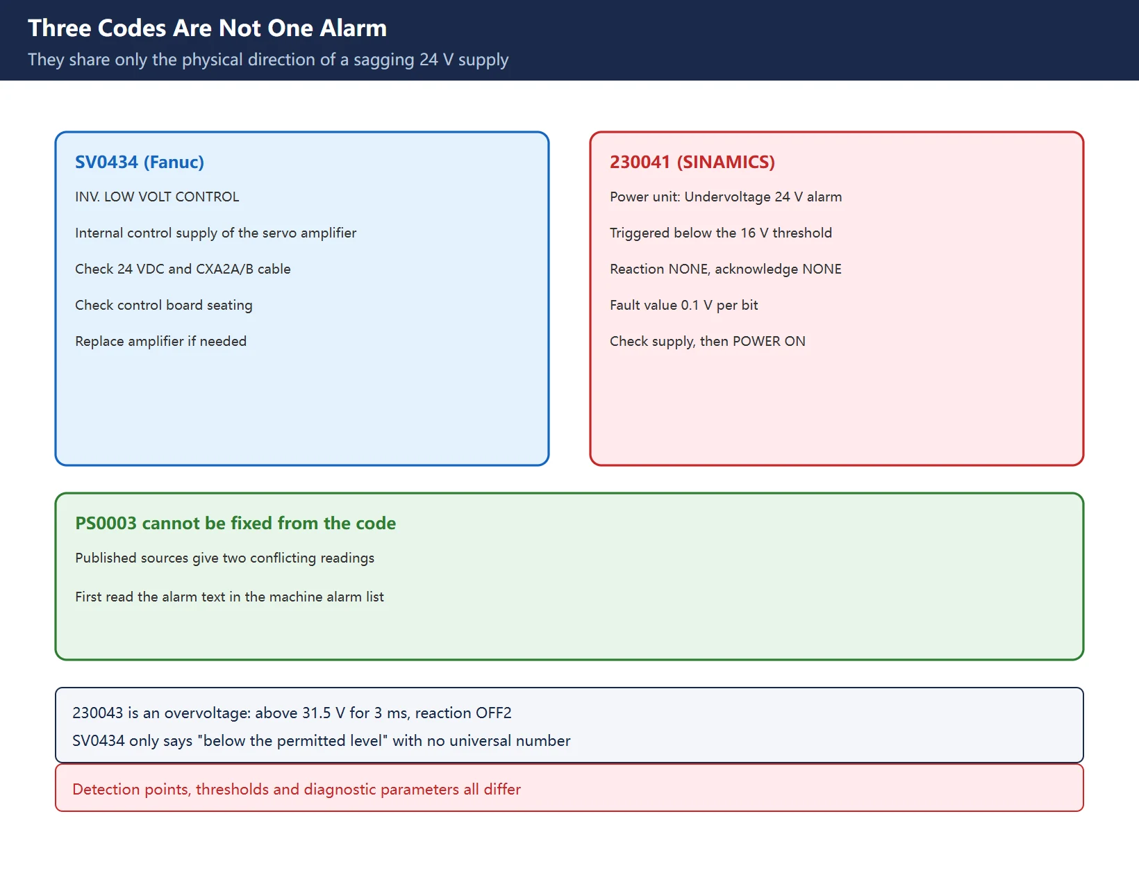
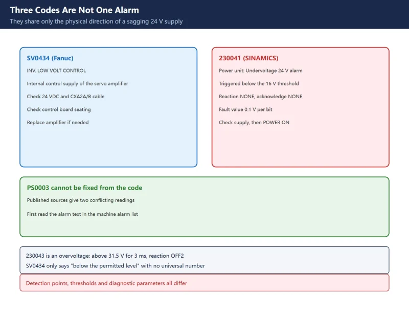
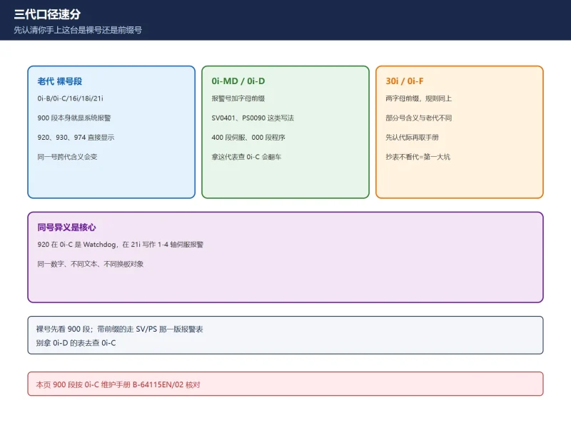
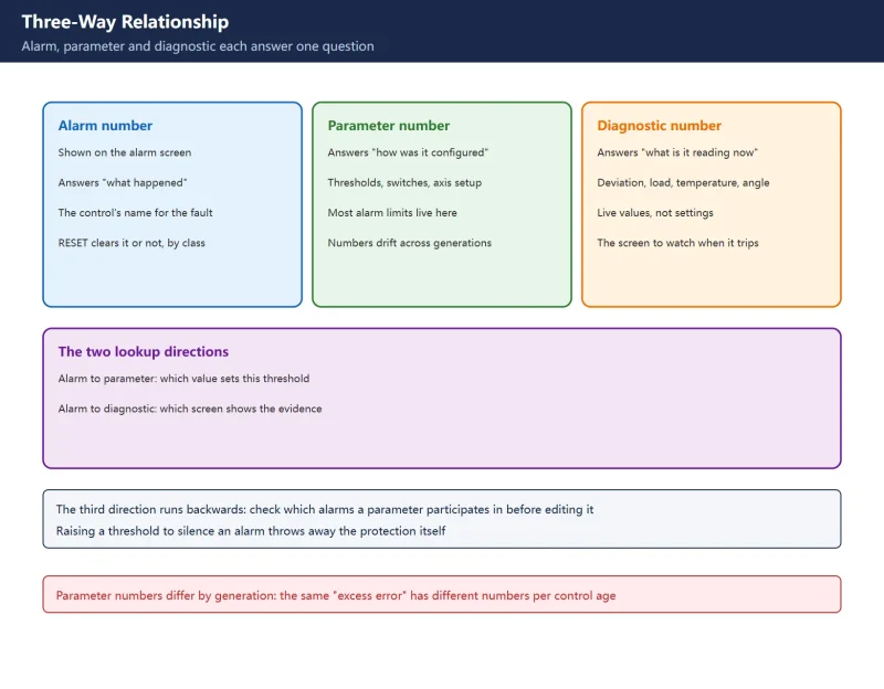
A circulating checklist places PS0003, SV0434 and 230041 side by side as “one physical fault, three brand codes”. They share only the physical direction of a sagging 24 V control supply; their numbering systems, detection points, thresholds, diagnostic parameters and system reactions are different and cannot be cross-read.
Table 1. Three numbering systems and adjacent entries
The official detail worth recording is 230041: the diagnostic manual states a 24 V supply fault with the 16 V threshold undershot, and the fault value (r0949, decimal) gives the 24 V voltage at 0.1 V per bit. The SERVO variant additionally uses r2124 in hexadecimal with a channel field (yy=0 for the 24 V supply, yy=1 for 48 V). That is neither the “below 22 V means failure” rule of thumb, nor SV0434‘s “below the permitted level” wording. SINUMERIK 840D sl Alarm List and CNC Alarm Number Formats by Brand help locate the number range first.
2. The PS0003 Number Conflict: One Code, Two Readings
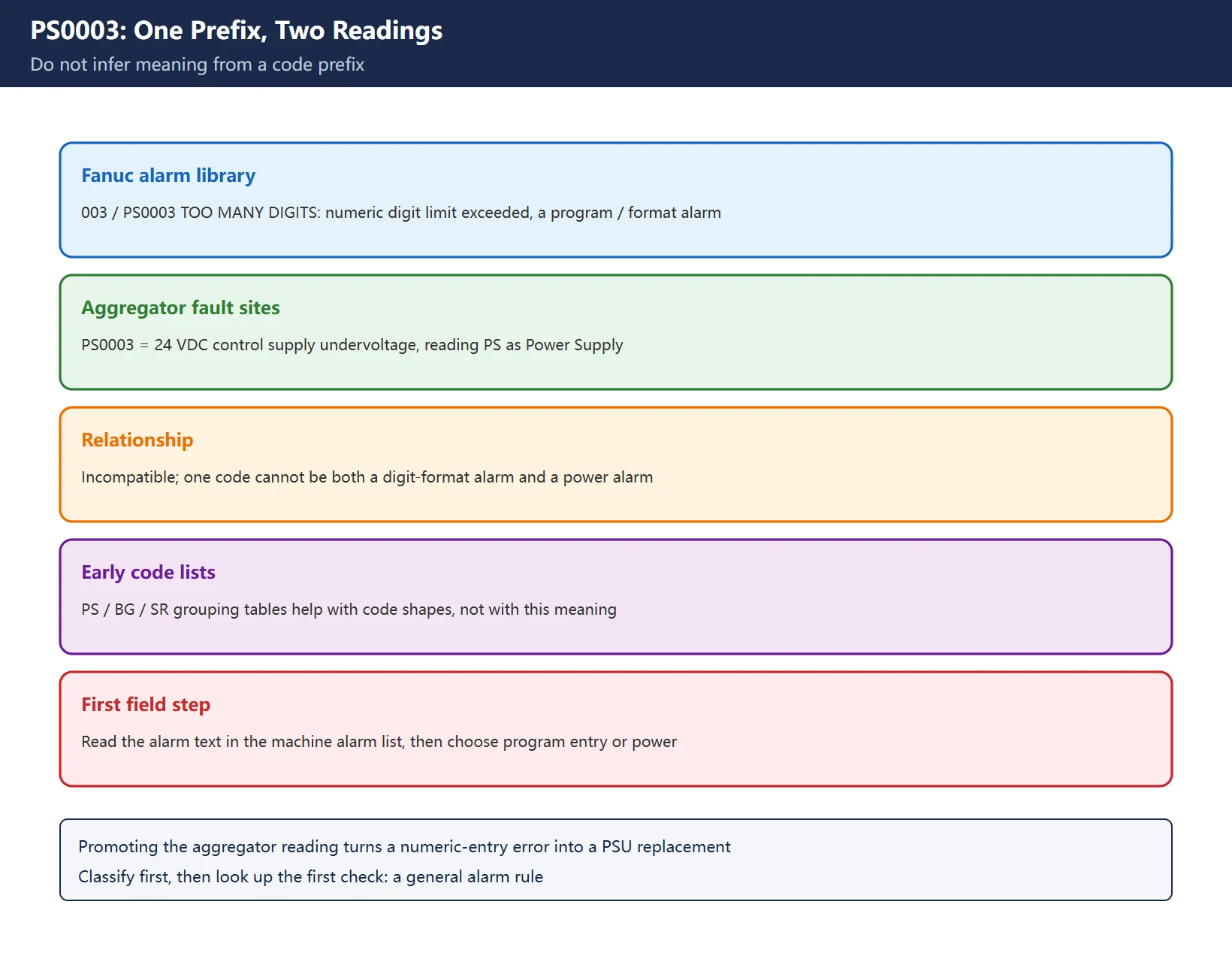
This is the single most important correction to the circulating checklist. Public sources give two entirely different, incompatible readings of PS0003:
| Source type | Reading of PS0003 | How it is justified | Judgement here |
|---|---|---|---|
| Fanuc alarm library (MTT) | 003 / PS0003 TOO MANY DIGITS: a value entered in a program, offset or setting screen has more digits than the field allows; a program / format alarm, unrelated to servo or drive | Explicitly states “This is a program and format alarm, not a servo or drive fault” | Has a concrete alarm text and remedy |
| Aggregator fault sites (industrialpro, cncfixtech and similar) | PS0003 Power Supply Alarm - Control Power Supply Error: 24 VDC control supply below threshold or failed | Infers “PS = Power Supply” and suggests 24 V plus/minus 5 percent and loading below 80 percent of rating | Conflicts with the row above; the PS prefix is read as Power Supply |
| General alarm-code lists | Number-group tables such as “Fanuc PS / BG / SR alarm quick reference” | Grouping only | Useful for code shapes, not for deciding what PS0003 means |
Table 2. The two conflicting readings of `PS0003`
The conclusion is blunt: do not infer meaning from a code prefix. If the screen shows PS0003, read the alarm text in the machine’s own alarm list. If it says “too many digits”, the direction is program and data entry; only if the text genuinely concerns control power does the power-supply direction apply. Promoting an aggregator’s reading into a universal troubleshooting table turns a simple numeric-entry error into an unnecessary PSU replacement. That is the same “classify first, then look up the first check” principle as CNC Alarm Number Formats by Brand.
3. Official Criteria and Field Rules of Thumb in Separate Columns
The circulating checklist offers a “voltage decision table”: 5 V rail at 5.00 V plus/minus 0.25 V with failure below 4.75 V; 24 V rail at 22-26 V with failure below 22 V; ripple measured on a multimeter AC range with failure above 100 mV AC on 5 V and 200 mV AC on 24 V. These figures are widespread in repair circles, but no such cross-brand official threshold set was verified in this review, so they must be listed separately.
| Value | Source level | Use here |
|---|---|---|
230041 triggers below the 16 V threshold | Official SINAMICS S120 Diagnostic Manual entry | Applies only to that alarm and drive object |
230043 above 31.5 V for 3 ms | Official entry in the same manual | Applies only to that overvoltage alarm |
SV0434 “below the permitted level” | Fanuc maintenance manual entry, no universal number | Check the machine manual's measurement point and tolerance |
4.75 V on 5 V, 22 V on 24 V and similar | Circulating checklist and field tables | Field screening lines, not official criteria |
100 mV AC / 200 mV AC ripple | Circulating checklist and third-party guides | A multimeter AC range is only a rough screen; bandwidth and true-RMS behaviour affect the reading, so it is not an acceptance test |
| Sustained load above 80 percent of rating | Third-party PSU sizing advice | Sizing experience, not an alarm threshold |
Table 3. Official thresholds versus empirical screening values
Merging them into one “official decision table” causes two problems: the official 16 V trigger sits next to the empirical 22 V line with no indication which one applies, and a multimeter AC reading is promoted to a ripple acceptance test that can condemn a healthy supply. The correct order is: read the alarm number and fault value, measure at the points specified in the machine manual, and only then use empirical values for rough screening. Sizing, headroom and thermal logic for switch-mode supplies belong to How to Read a CNC Machine Electrical Schematic and the machine’s power schematic.
4. No-Load versus Load Separation
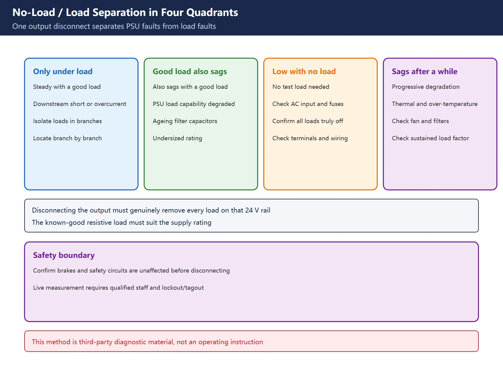
This is the most complete and most useful method in the third-party diagnostic guides: one output disconnect separates “PSU bad” from “load bad”.
| Behaviour after disconnecting the output | With a known-good resistive load | More likely direction | Next step |
|---|---|---|---|
| No-load output normal, collapses with the original load | Voltage stays steady | Downstream overcurrent or partial short | Isolate loads branch by branch |
| No-load output normal, collapses with the original load | Voltage also collapses | PSU load capability degraded (ageing filter capacitors, undersized rating) | Check output capacitors, rating and temperature rise |
| No-load output already low or unstable | Not needed | Input side, the PSU itself, or a load that was not actually disconnected | Check AC input, fuses, wiring and whether all loads are truly off |
| No-load normal, collapses after a period of running | Progressively worse | Thermal and over-temperature protection | Check fan, filters, cabinet temperature and sustained load factor |
Table 4. Four-quadrant reading of no-load / load separation
Three field cautions. First, “disconnect the output” must genuinely remove every load on that 24 V rail, or the fourth column fails. Second, a known-good resistive load (a 24 V lamp or power resistor) separates PSU capability from downstream loading; its power must suit the supply rating, so do not use a load far above it. Third, this is not the same circuit as the 24 V safety chain in Fanuc Emergency Stop Circuit: before disconnecting, confirm that brakes and safety circuits are unaffected, and see Fanuc Gravity-Axis Brake for the vertical-axis boundary.
5. Ripple, Voltage Drop and Segmented Isolation
Table 5. Six checks and their boundaries
“High ripple makes the CNC read an unstable supply as a logic error” is a useful mechanism, but it is an explanation rather than a pass/fail criterion. What closes the loop is correlating symptom and event: align alarm-history timestamps with solenoid actuation, spindle start or cabinet temperature rise, then measure voltage drop on that branch. Reading drawings and reverse-looking-up wire numbers is covered in How to Read a CNC Machine Electrical Schematic.
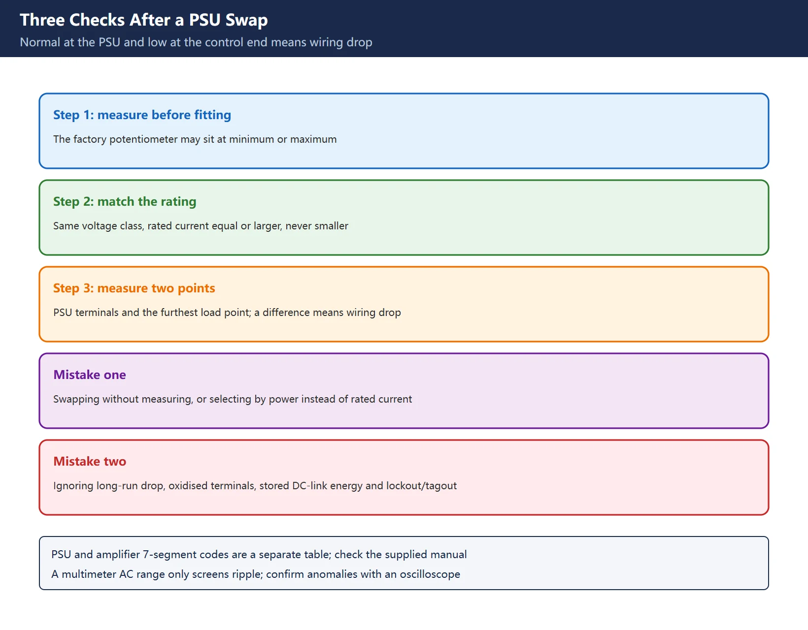
6. Three Checks After a PSU Swap
| Step | Action | Why |
|---|---|---|
| 1 | Measure the new PSU output before fitting it | The factory potentiometer may sit at minimum or maximum; fitting it directly can over- or under-voltage the control |
| 2 | Match voltage class and rated current; equal or larger is acceptable, smaller is not | An undersized unit sags at load peaks and looks like “the new PSU is bad too” |
| 3 | After fitting, measure at the PSU terminals and again at the furthest load point | A difference between the two readings points to wiring drop, not the PSU itself |
Table 6. Three checks after the swap
Four recurring mistakes: swapping without measuring, selecting by power rather than rated current, ignoring long-run voltage drop and oxidised terminals, and forgetting DC-link stored energy plus lockout/tagout. Third-party notes also mention 6 on the power module display and 2 on the servo amplifier; such cross-layer code tables must be checked against Fanuc Servo Alarm Reference Chart, Fanuc Servo Amplifier Alarm Codes and the supplied manual, not used alone to condemn a whole drive group. Related field cases are in Fanuc Tool Change Stuck.
7. Site Index
Table 7. Eight further reading links
Frequently Asked Questions
What does PS0003 mean, and what 24 V control voltage is normal?
PS0003 cannot be interpreted from its prefix: the Fanuc alarm library reads it as TOO MANY DIGITS, a program / format alarm for a numeric value exceeding a field’s digit limit, while several aggregator sites read it as a 24 VDC control-supply undervoltage. The two conflict. Read the alarm text in the machine’s own alarm list first. As for voltage, no cross-brand official “normal range” was verified: the 230041 diagnostic manual entry states a 16 V threshold, 230043 states 31.5 V for more than 3 ms, and SV0434 only says “below the permitted level” without a universal number. The widely copied 4.75 V on 5 V and 22-26 V on 24 V are empirical screening lines; check them against the measurement points and tolerances in the supplied manual rather than presenting them as official.
Output is normal with no load but sags under load. Is it the PSU or the load, and how do I tell?
Use no-load / load separation. Disconnect the output and power up: normal with no load but collapsing with the original load points to a downstream partial short or overcurrent, and a steady voltage with a known-good resistive load confirms it. If the voltage also collapses with that known-good load, the PSU’s own load capability is more likely degraded through ageing capacitors or an undersized rating. If no-load output is already low, check AC input, fuses and whether every load was truly disconnected. Add one more check after any swap: measure at the PSU terminals and at the furthest load point, because a difference between the two is wiring voltage drop, not a bad PSU. This method comes from third-party diagnostic guides; before disconnecting any output, follow lockout/tagout and the builder’s procedure and confirm brakes and safety circuits are unaffected.
How do I handle 230041 on an 828D, and is it the same as Fanuc SV0434?
They are different numbering systems with a similar physical direction. 230041 is the “Power unit: Undervoltage 24 V alarm” in the SINAMICS S120 / SINUMERIK diagnostic manual: a 24 V supply fault with the 16 V threshold undershot, reaction NONE, acknowledge NONE, a fault value in 0.1 V per bit, and a remedy of checking the 24 V supply and performing a POWER ON on that component. SV0434 is an undervoltage of the Fanuc servo amplifier’s internal control supply, whose official entries call for checking the 24 VDC control supply, the inter-amplifier communication cable and control board seating, then replacing the amplifier if needed. Detection points, thresholds and diagnostic parameters differ, so remedies cannot be swapped; check each in its own manual and use no-load / load separation for the shared physical root cause.
Last updated: 2026-11-15
Where to go next
- FANUC Troubleshooting — the full guide library: alarms, diagnosis numbers, servo, spindle, PMC and electrical faults, organised by symptom.
- CNC Repair Tools — which instrument measures what: multimeters, clamp meters, insulation testers and oscilloscopes, with the specification that actually matters.
- Remote Technical Support — have the readings reviewed with you: alarm reverse lookup, PMC ladder analysis and servo tuning advice by call. Repair companies and integrators welcome.
Read the guide, get the right instrument, or walk the diagnosis through with someone — pick whichever you need.
The original Chinese version — same procedure, with the full field notes.

















暂无评论内容