


🚨 Scope and compliance: The standard-part mapping and item-family names on this page follow the public ISO 230 series overviews and the official catalogue abstract of
GB/T 17421.1-2023, “Test code for machine tools – Part 1: Geometric accuracy of machines operating under no-load or quasi-static conditions” (identical to ISO 230-1:2012, effective 2024-03-01, fully replacing the 1998 edition), plus the public entries for the positioning-accuracy partGB/T 17421.2. Standard text, inspection diagrams and tolerance tables are copyright-protected. This page states only part numbers and item-family names; it reproduces no clauses, diagrams or numerical tolerance tables, and offers no standard downloads, cloud-drive links or bundled files. Per-item tolerances, instrument accuracy grades, measuring-point counts and environmental conditions must come from the machine’s supplied acceptance records, the builder’s product inspection standard and the contract. Different accuracy classes and machine configurations differ by an order of magnitude, so this page deliberately publishes no universal acceptance number. The widely copied “seven-item geometric error list” comes from a single third-party service case on one specific machining centre with a B-axis rotary table and a T-axis; it is not a universal item list. Adjustment locations such as “Y-direction slide shims” or “replace the right-hand Z slide” are that machine’s repair record, presented here only as a case note, never as a general procedure. Shimming, scraping, bearing preload and lifting work involve heavy assemblies, stored spring energy and live conductors; only qualified personnel following the builder’s written procedure and lockout/tagout rules should perform them. This page is not a work instruction.
30-Second Triage: Get the Standard Part Right Before Discussing Limits
| What you are doing | Governing part | Instrument family | What not to do first |
|---|---|---|---|
| Accepting a new machine / rechecking geometry (squareness, parallelism, flatness, straightness, runout) | ISO 230-1 / GB/T 17421.1 | Precision levels, granite squares, test arbors, dial / test indicators, laser optics | Do not reach for an ISO 230-2 A / R report |
| Axis positioning accuracy, repeatability, reversal error | ISO 230-2 / GB/T 17421.2 | Laser interferometer | Do not substitute a ballbar polar plot for point-by-point data |
| Two-axis circular contours, reversal spikes, servo mismatch | ISO 230-4 / GB/T 17421.4 | Telescoping ballbar | Do not write roundness deviation into a squareness column |
| Thermal drift from warm-up and ambient change | ISO 230-3 / GB/T 17421.3 | Displacement / temperature sensors | Do not judge thermal drift on a cold machine |
| Rotary-axis (A / B / C) geometric accuracy | ISO 230-7 | Test mandrel, laser | Do not force rotary-centre errors into a three-axis geometry table |
| Body-diagonal / volumetric screening | ISO 230-6 | Laser tracer | Do not let it replace single-axis point-by-point measurement |
| Shop-floor alignment and shimming | Builder assembly / service procedure plus supplied acceptance sheet | Dial indicators, test arbors, shims, levelling pads | Do not present alignment readings as an acceptance report |
Table 0 – Seven common tasks and their governing parts
A useful mental model is that the ISO 230 series is split by test object, not by “how accurate should the machine be”. The tolerance itself comes from a different document entirely: the builder’s declaration, the product inspection standard for that model, or the signed acceptance protocol.
1. Verification versus Alignment Are Two Different Jobs
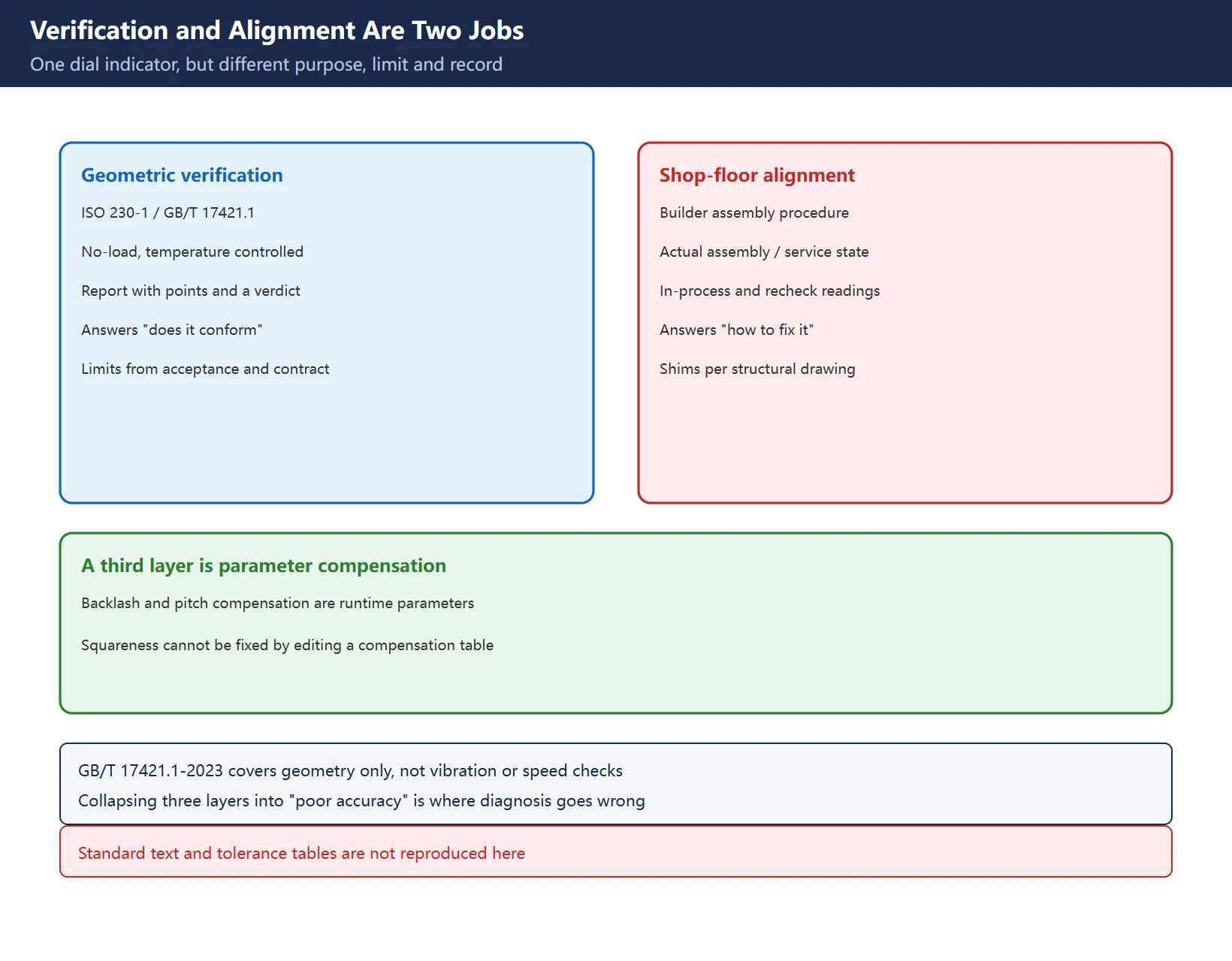
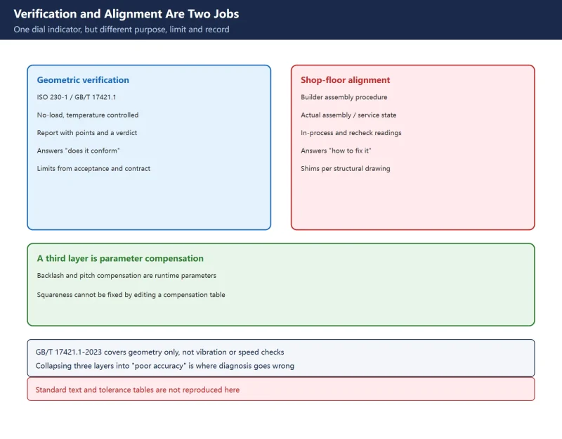
Verification takes values under defined conditions (no-load or quasi-static, stabilised temperature, levelled installation) and produces a report answering “does this machine conform”. Alignment is the assembly or service act of restoring the geometric relationship with shims, scraping and tightening, answering “how do we make it conform”. The same dial indicator may be used for both, but the purpose, the acceptance limit and the record are entirely different.
| Dimension | Geometric accuracy verification | Shop-floor alignment |
|---|---|---|
| Governing document | ISO 230-1 / GB/T 17421.1 plus the model's product inspection standard | Builder assembly / service procedure, supplied acceptance sheet |
| Machine state | No-load or quasi-static; temperature and installation level controlled | Often the actual assembly / service state, possibly with fixtures attached |
| Output | Acceptance report with measuring points, directions, environment and a verdict | In-process readings and a post-tightening recheck value |
| Limit | Given by supplied acceptance data and contract, graded by machine class | Constrained by the process card and the drawing datums |
| Typical misuse | Treating alignment readings as the acceptance verdict | Using an instrument report to dictate shim thickness |
Table 1 – Five differences between verification and alignment
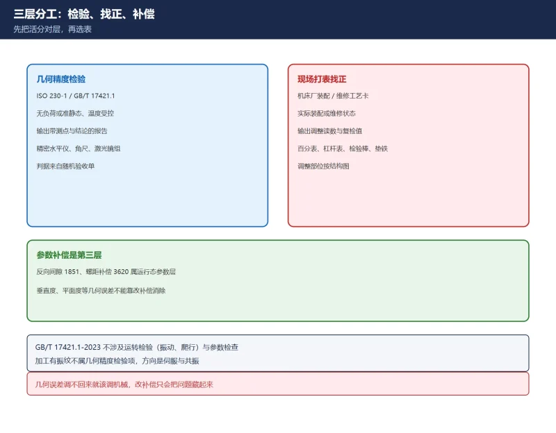
The official abstract of GB/T 17421.1-2023 also draws two boundaries worth keeping: the part deals only with geometric accuracy, not with operating checks (vibration, stick-slip) or parameter checks (speeds, feedrates), and it does not cover high-speed machine motions where cutting forces are normally smaller than acceleration forces. Vibration, chatter and surface finish therefore sit outside a geometric-accuracy item list; see the site’s Fanuc Servo Resonance and Notch Filter Setup and Fanuc Servo Load Meter Explained for that separate layer.
2. Error Family Framework Table (Core of This Page)
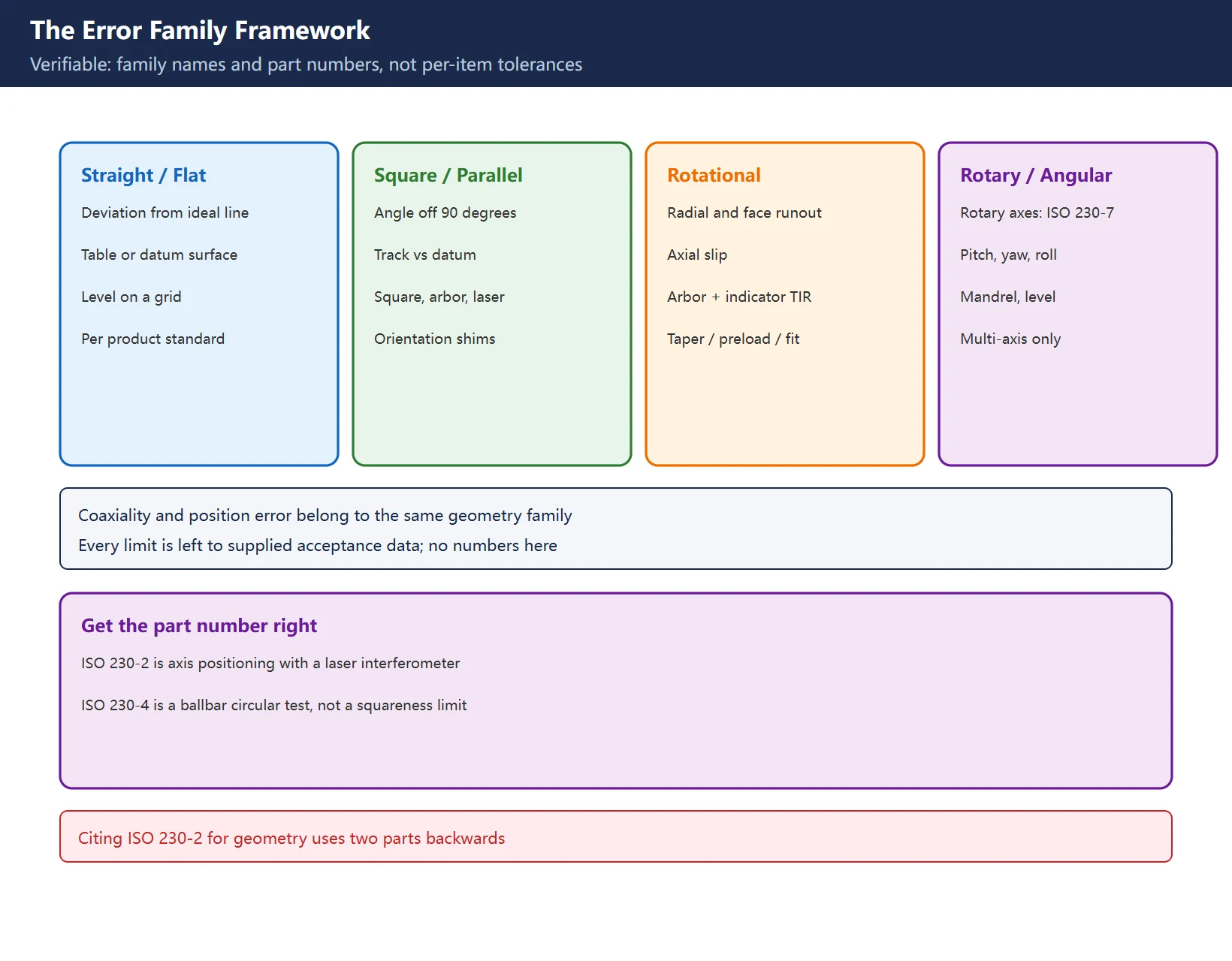
What can be verified is the family name and the governing part, never the per-item tolerance of a particular machine. The table below gives instrument family, tolerance provenance, typical adjustment location and recheck method for each family, leaving every number to the supplied documentation.
| Error family | Official item name (family) | Instrument family | Tolerance provenance | Typical adjustment location (family) | Recheck method |
|---|---|---|---|---|---|
| Straightness | Deviation of a moving member from an ideal line, in horizontal / vertical planes | Precision level, straightedge, laser straightness optics | Model product inspection standard + GB/T 17421.1 | Guideway supports, levelling pads, anchors, gib preload | Same method and points, with a comparison record |
| Flatness | Flatness deviation of a table or datum surface | Precision level on a grid, straightedge, laser | Same as above | Support pads, table fastening, foundation level | Grid remeasurement using the same evaluation method |
| Squareness / orthogonality | Deviation of the angle between two axes from 90 degrees | Granite square + test indicator, laser squareness optics | Same as above | Column / saddle relative position, orientation shims | Measure in both directions, recheck after tightening |
| Parallelism | Parallelism of a motion trajectory to a datum surface or another axis | Test arbor + test indicator, precision level | Same as above | Headstock / slide position, support shims | Read near and far points; record the measuring distance |
| Rotational accuracy | Spindle radial runout, face runout, axial slip | Precision test arbor + test indicator / electronic probe | Same as above | Bearing preload, taper and interface parts, locking parts | Slow hand rotation for TIR, record cold and warm states |
| Coaxiality / position error | Offset of two rotation centre lines, spindle-to-table position | Test arbor + test indicator, coaxiality fixture | Same as above | Housing location, bearing seats, couplings | Repeat with the same datum and re-clamp to confirm |
| Angular deviation | Pitch, yaw, roll of linear axes | Electronic level, autocollimator, laser angular optics | Same as above | Guideway and slide supports, gibs | Segmented remeasurement over full travel |
| Rotary-axis geometry | Centre of rotation error, indexing and axis relationships | Test mandrel, laser, precision indexing device | ISO 230-7 + model rotary-table inspection standard | Rotary-table support, worm gear set / direct-drive datum | Multiple angles, both directions |
Table 2 – Eight error families with instrument, provenance and adjustment framework (no per-item tolerances)
The value of this table is that it can be cited correctly. When writing an acceptance plan, a retrofit proposal or a used-machine evaluation, an engineer needs the item name and the governing part, not a number table of unknown provenance. On this site, Fanuc Backlash Compensation 1851 and Fanuc Pitch Error Compensation 3620-3624 belong to the parameter compensation layer; ISO 230-2 / 230-4 reports belong to the measurement and judgement layer; this page and shop-floor alignment belong to the mechanical adjustment layer. The three layers are not interchangeable.
3. Item by Item: Instrument and Adjustment Location as Method Families Only
3.1 X-to-Y Squareness / Orthogonality
Method family: establish a 90 degree datum with a precision square or granite square and read the deviation with a test indicator while one axis traverses, or use laser squareness optics. The limit comes from the model’s product inspection standard and the contract – no universal angular value is given. Typical adjustment locations are the relative column / saddle position and orientation shims, with the exact location taken from the machine’s structural drawing. “Traverse the T axis, adjust the A-direction shims” is a record from one specific machine with a T axis; a conventional three-axis vertical machining centre has no T axis, so it cannot be copied.
3.2 Spindle Axis to X Squareness
Method family: fix the indicator stand at the spindle side, traverse X at uniform speed and read the difference between the two ends, using a test arbor where spindle runout must be excluded. The limit follows the supplied acceptance sheet. The adjustment location is usually the headstock / slide relative position or Y-direction support shims; the shim thickness and location are set by the builder’s assembly procedure. “Adjust the Y-direction slide shim thickness” is one case report’s wording, not a general procedure.
3.3 Z Axis to Spindle Axis Parallelism
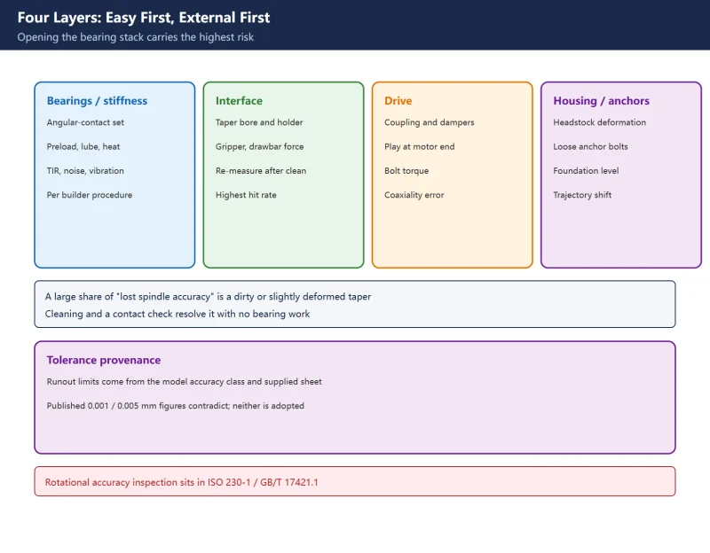
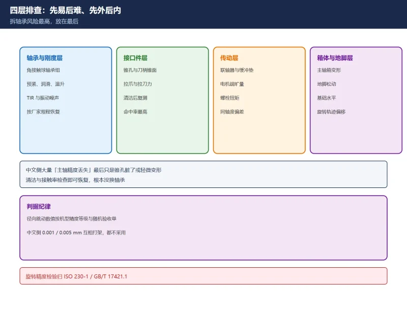
Method family: insert a test arbor into the spindle taper and read the indicator at near and far positions from the nose (the measuring distance follows the machine’s inspection card; third-party write-ups variously use 30/180 mm and 100/300 mm, so no single pair is adopted here). A far reading markedly larger than the near one points towards support stiffness, arbor seating tilt or the taper interface, and must be subdivided further with a high-spot phase test – two readings alone do not justify a bearing-preload diagnosis. See Spindle Runout: Four-Layer Diagnosis for that split.
3.4 B Axis / Rotary Table Flatness
Method family: read the table surface or rotary trajectory at multiple points (for example a four-point method) to identify the direction of slide or guideway wear. A B axis is not standard equipment on a general three-axis machining centre; this item applies only to four- / five-axis machines with a rotary table, and its governing document is closer to ISO 230-7 plus the model’s rotary-table inspection standard. “Replace the right-hand Z slide” is one ten-year-old machine’s repair record, not an adjustment rule.
3.5 Spindle Cover / Face Runout
Method family: rotate the spindle slowly by hand and read radial and face TIR at several points. The limit follows the model’s spindle accuracy class and supplied acceptance sheet. The adjustment location is the cover / end-cap fixing position and tightening sequence; if the high spot stays at a fixed angular position, distinguish interface contamination, bearings and shaft bow (see Spindle Runout: Four-Layer Diagnosis).
4. Provenance Discipline: Four Classes of Content Not to Fabricate
| Not to be fabricated | Why | Correct wording |
|---|---|---|
| Per-item tolerance numbers (e.g. “squareness <= 0.02/1000” as a universal limit) | Accuracy classes, machine sizes and travels differ by an order of magnitude; the standard specifies test methods and reporting structure, while limits come from the acceptance sheet / contract / product standard | “Per the supplied acceptance data and this model's product inspection standard” |
| Instrument accuracy grades and measuring-point counts | ISO 230-1 and GB/T 17421.1 do specify points, directions and environmental conditions, and the counts, cycles, approach directions and temperature bands differ between editions | “Per the adopted edition of the standard and the inspection card”, naming the edition |
| Clause numbers and inspection diagrams | The official text was not verified clause by clause; reproducing clauses and diagrams raises copyright issues | Give only the part number and the item-family name |
| Machine-specific adjustment locations and shim values | “Y-direction slide shims” and “right-hand Z slide” come from one case report; structures differ | Label it a case and say “per the structural drawing and assembly procedure” |
Table 3 – Four classes not to fabricate and the wording to use instead
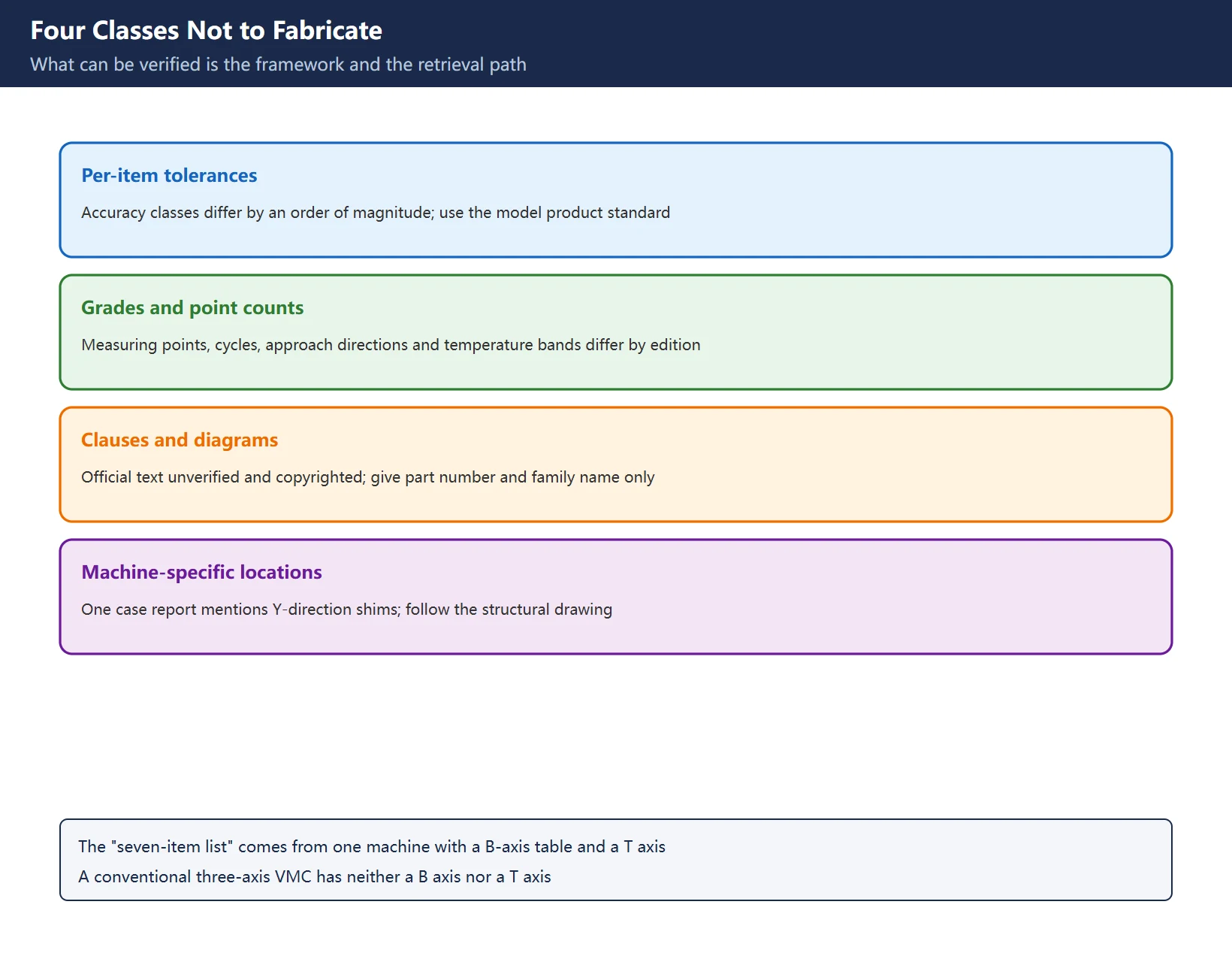
One version fact is routinely missed: GB/T 17421.1-2023 renamed the part from the 1998 edition’s “no-load or finishing conditions” to “no-load or quasi-static conditions” and fully replaced the old edition. An acceptance document that merely says “per GB/T 17421.1” should state which edition, otherwise two reports cannot be compared directly. The site’s Used CNC Machine Electrical Inspection Checklist applies the same discipline: what can be verified is the framework and the retrieval path, while the numbers are checked against supplied documentation.
5. Verification After Adjustment
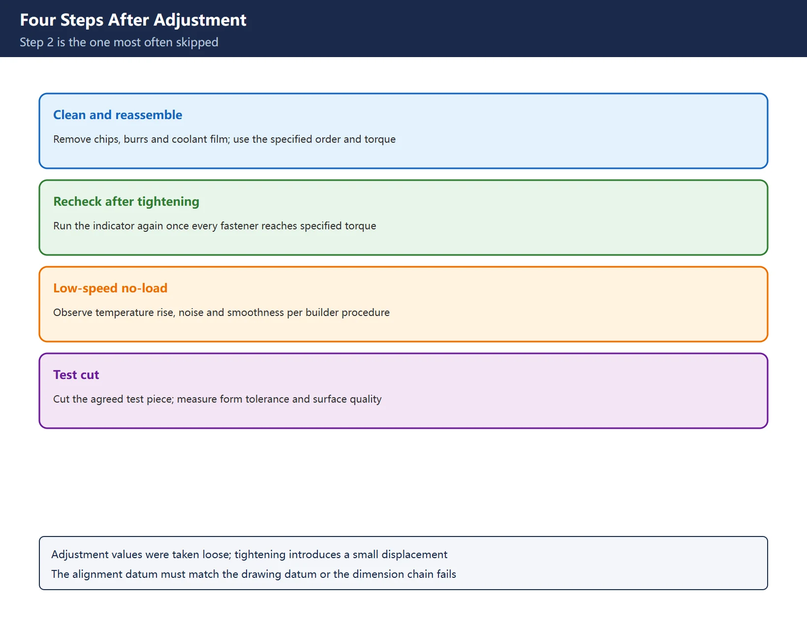
| Step | What to do | Common trap |
|---|---|---|
| 1 Clean and reassemble | Remove chips, burrs and coolant film from mating faces; reassemble in the specified order and to the specified torque | Unclean mating faces cause “it moved again after adjustment” |
| 2 Recheck after tightening | Run the indicator again once every fastener reaches the specified torque | Recording only in-process readings and never rechecking – the most common failure point |
| 3 No-load running observation | Run at low speed per the builder's procedure; watch temperature rise, noise and motion smoothness | Comparing a warm reading directly with a cold acceptance value |
| 4 Test cut | Machine the agreed standard test piece / test program and measure form tolerance and surface quality | Alignment datum not matching the drawing design datum, so the dimension chain will not close |
Table 4 – Four post-adjustment verification steps and their traps
Step 2 deserves emphasis: the adjustment value was obtained in a loosened or partly tightened state, and tightening introduces a small displacement. Without a recheck there is no evidence the adjustment worked. Datum consistency in step 4 is equally important – the alignment datum must match the drawing design datum. Over-pursuing alignment accuracy also increases setup time significantly; the target should match the process tolerance.
6. Site Index and Retrieval Path
Table 5 – Eight further reading links
When looking up official material, search by “standard number + edition year + part title” (for example ISO 230-1:2012, GB/T 17421.1-2023), then find per-item limits in the model’s product inspection standard. Do not search by page or clause numbers from a web “quick table” – those identifiers are usually second-hand compilations.
Frequently Asked Questions
Which items does a machine geometric accuracy inspection cover, and under which standard?
By error family: straightness, flatness, squareness / orthogonality, parallelism, rotational accuracy (spindle radial and face runout, axial slip), coaxiality / position error, angular deviation (pitch / yaw / roll), plus rotary-axis geometric accuracy. The test methods for the first seven sit in ISO 230-1, adopted identically in China as GB/T 17421.1-2023 (no-load or quasi-static conditions, replacing the 1998 edition); rotary axes have ISO 230-7. The frequently confused part is ISO 230-2 / GB/T 17421.2, which covers positioning accuracy and repeatability of numerically controlled axes measured point by point with a laser interferometer – not geometric accuracy. Circular tests / ballbar belong to ISO 230-4, thermal effects to ISO 230-3 and body diagonals to ISO 230-6. Per-item tolerances are not in these general parts; they come from the model’s product inspection standard, the supplied acceptance sheet and the contract.
Can the circulating “geometric accuracy tolerance table” be used directly, and why do its numbers contradict each other?
No. Three recurring problems: the governing part is wrong (geometric accuracy attributed to ISO 230-2); a “seven-item” list from one service case on a machine with a B-axis rotary table and a T axis is presented as a universal checklist for a three-axis VMC, which has neither a B axis nor a T axis; and per-item tolerance numbers are published even though accuracy classes and machine sizes differ by an order of magnitude, so Chinese-language compilations contradict each other on the same item. The right approach is to use Table 2 above to map the item family, then read the limit from the supplied acceptance data and the builder’s product inspection standard, naming the standard edition. This page deliberately publishes no universal acceptance number.
Should alignment be rechecked afterwards, and why?
Yes – and specifically after every fastener reaches its specified torque, run the indicator again. The adjustment reading was taken in a loosened or partly tightened state, and tightening introduces a small displacement; recording only the in-process value provides no verification that the adjustment held. A complete loop has four steps: clean mating faces and reassemble per procedure, recheck after tightening, observe temperature rise and motion smoothness at low speed per the builder’s procedure, then cut the agreed test piece and measure form tolerance and surface quality. Also confirm the alignment datum matches the drawing design datum, otherwise the dimension chain will not close; and match the accuracy target to the process tolerance, since over-pursuing it only increases setup time.
Last updated: 2026-11-15
Where to go next
- FANUC Troubleshooting — the full guide library: alarms, diagnosis numbers, servo, spindle, PMC and electrical faults, organised by symptom.
- CNC Repair Tools — which instrument measures what: multimeters, clamp meters, insulation testers and oscilloscopes, with the specification that actually matters.
- Remote Technical Support — have the readings reviewed with you: alarm reverse lookup, PMC ladder analysis and servo tuning advice by call. Repair companies and integrators welcome.
Read the guide, get the right instrument, or walk the diagnosis through with someone — pick whichever you need.
The original Chinese version — same procedure, with the full field notes.




















暂无评论内容