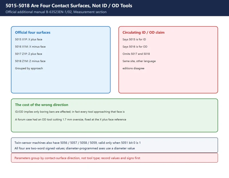



🚨 Scope and compliance: The four-surface definition of 5015-5018, their data type and valid range come from the official Fanuc additional manual
B-63523EN-1/02(Sauter-Turret with 2nd Geometry Tool Offset Data Function for 16i-TB / 18i-TB / 21i-TB, Measurement section). The skip system variables#5061–#5063, the G36/G37 split, the SKIP signal path, Renishaw Inspection Plus macro numbers,6200bit polarity,5091/5092safety limits and8133bit meanings come from published third-party technical sites and service forums; no corresponding official Fanuc manual text was verified here, so all of these are labelled third-party and are not instructions to change parameters. Manual text, bit-definition figures and per-number descriptions are copyright material; this page explains mechanisms, lookup paths and field discipline only, and offers no manual download link, file mirror, archive or bundled package. Every parameter number, bit definition, macro number and unit must be checked against the CNC model, software version, supplied manual and builder specification; measurement functions can be remapped between generations and by the machine builder.
30-Second Triage: Identify Which Case You Have
Table 0 – Eight symptoms and the first diagnostic line
1. What 5015 / 5016 Actually Are: The Manual Defines Four Contact Surfaces
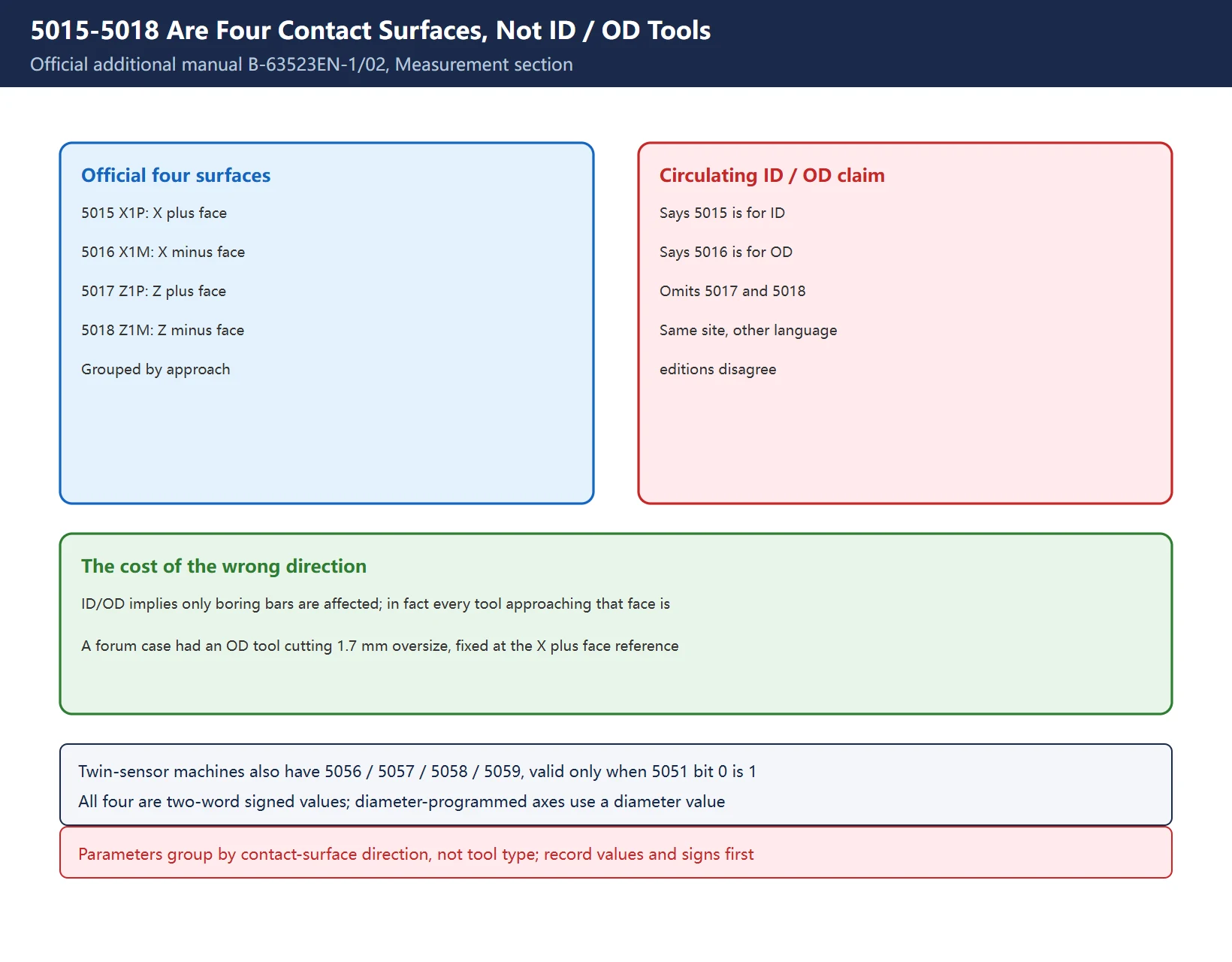
This is the most misquoted layer online. Chinese and English reposts routinely say “5015 is for ID (internal) tools, 5016 for OD (external) tools”. But the official Fanuc additional manual B-63523EN-1/02 lists all four numbers in one table under the heading “distance between the measurement reference position and the sensor contact surface”:
| Parameter | Official meaning (touch sensor 1 side) | Field reading |
|---|---|---|
| 5015 | X1P: distance to the X axis plus contact surface | Reference for tools approaching in +X |
| 5016 | X1M: distance to the X axis minus contact surface | Reference for tools approaching in -X |
| 5017 | Z1P: distance to the Z axis plus contact surface | Length reference for +Z approach |
| 5018 | Z1M: distance to the Z axis minus contact surface | Length reference for -Z approach |
Table 1 – The 5015-5018 four-surface definition (from `B-63523EN-1/02`, Measurement)
The same table adds four limits that reposts nearly always omit:
- There is a second set:
5056/5057/5058/5059are X2P / X2M / Z2P / Z2M for touch sensor 2, and the manual states they are valid only when bit 0 (2NR) of parameter5051is 1. On twin-sensor machines, check that bit first. - Data type is two-word, valid range
−99999999to99999999. - Units follow the increment system: IS-A 0.01 mm, IS-B 0.001 mm, IS-C 0.0001 mm, with a separate set for inch input. The popular claim “one parameter unit equals one micron” only holds for IS-B metric machines.
- Axes under diameter programming are set using a diameter value. This decides whether a 5015 correction is a radius difference or a diameter difference – get it wrong and the result is out by a factor of two.
The manual also notes these parameters serve the function “to input tool offset value measured B”. In other words, they describe where the setter hardware sits in the machine coordinate system, not the compensation of any individual tool. Each tool’s compensation still lives in its own geometry / wear offset.
2. Why “5015 = ID / 5016 = OD” Misleads
Tellingly, one third-party technical site contradicts itself across language editions: its Traditional Chinese article follows the official manual (5015 = X+ face, 5016 = X− face, 5017 = Z+ face, 5018 = Z− face), while another article states “5015 is for ID tools, 5016 for OD tools, with Mitsubishi equivalents 2015 / 2016”. The brief that prompted this page quoted the latter.
| Version | Source type | Problem |
|---|---|---|
| Four contact surfaces 5015-5018, two-word, signed, direction-defined | Official Fanuc additional manual | Verifiable; used as the baseline here |
| 5015 = ID tool / 5016 = OD tool | Single third-party article (its own language editions disagree) | Replaces “approach direction” with “tool type” and hides 5017 / 5018 entirely |
| The block near 5015 is a function-specific area the builder may remap | Another article on the same site | The warning itself is useful: builders do remap measurement functions |
Table 2 – Three circulating versions and their trust boundaries
This is not wordplay. Under the ID/OD reading you would assume editing 5015 only affects boring bars. Under the official definition it affects every tool approaching that face from +X. A classic forum case makes the point: an OD turning tool cut 31.7 mm instead of 30 mm, and the fix was adding or subtracting 1.7 mm at 5015 – an external tool, corrected through the X+ face reference.
🔑 Remember: the parameters are grouped by contact-surface direction, not by tool category. The same third-party source also warns that before editing you must confirm the numbers against the parameter manual for your control and software series, because the block around 5015 is function-specific and builders occasionally remap measurement functions.
3. The Calibration Formula and a Six-Step Field Procedure
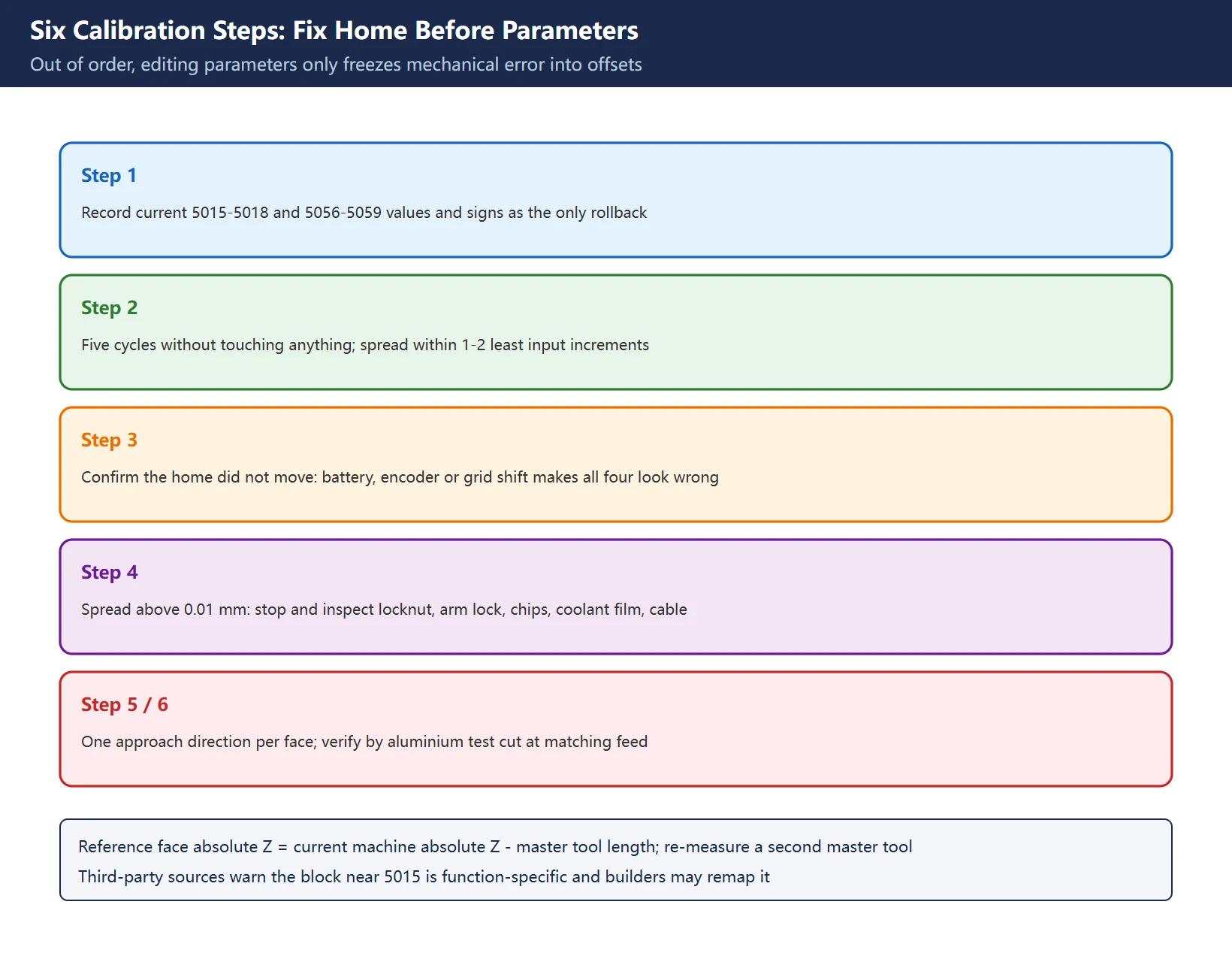
Third-party engineering sources give the reference-face calculation as: absolute Z of the setter reference face = current absolute Z of the machine − length of the master tool. In practice, jog a master tool of known length until it just touches the setter top face, read the machine coordinate, subtract the master tool length, and that is the setter face position in machine coordinates. After writing it back, measure a second known master tool and confirm the resulting compensation matches expectation.
What actually decides whether calibration succeeds is the discipline before any edit:
| Step | Action | Criterion / why |
|---|---|---|
| 1 | Record the current 5015-5018 (and 5056-5059) values and their signs | The sign reflects the builder's convention and beats any generic rule; it is also your only rollback |
| 2 | Without touching anything, run five measurement cycles on one tool and log the compensation | Spread within 1-2 least input increments means the mechanics are sound; above 0.01 mm, stop |
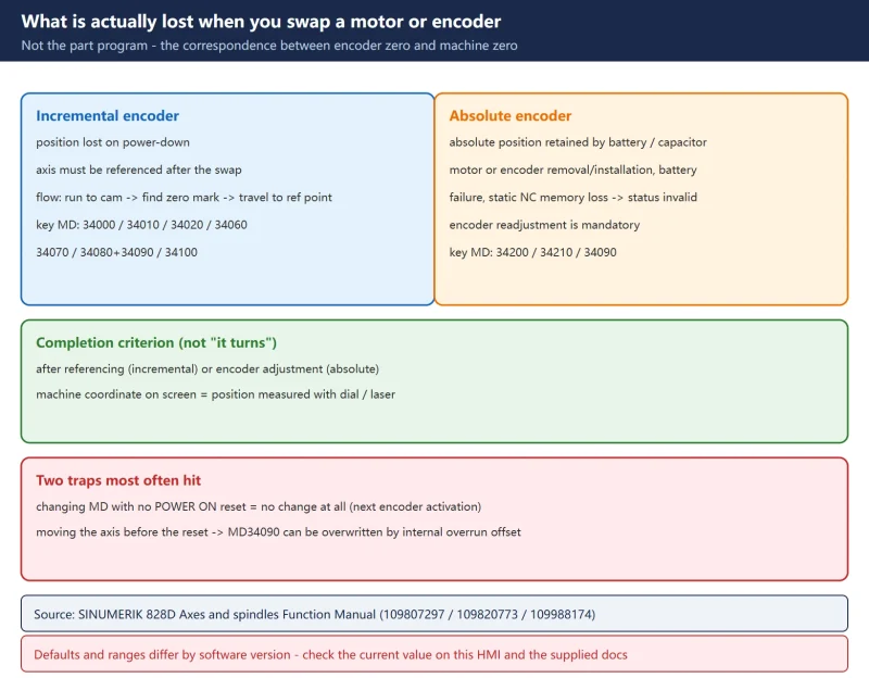
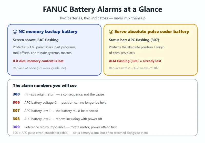
| 3 | Confirm the reference return position has not moved | A servo battery swap, encoder replacement or edited grid shift moves machine zero, making all four parameters look wrong at once |
| 4 | Inspect the stylus locknut, arm lock, stop, chips and coolant film on the face, and the drag-chain cable | This is the checklist when step 2 fails – no parameter edit will fix it |
| 5 | Approach each face from one direction only | Approaching in reverse adds lost motion into the reading |
| 6 | Verify with a test cut in aluminium, at the same feed used during calibration | A test cut is the only way to close the loop from calibration value to real part size |
Table 3 – Six calibration steps and the criterion for each
Always leave a rollback path: editing CNC parameters carries the real risk that a wrong number or typo immediately changes machine behaviour and can cause a crash or scrap parts. If you are not experienced with parameter edits, the correct move is to contact the machine builder or local dealer rather than probing on a production machine. See Exporting / Printing FANUC Parameter Tables and Ladder for archiving, and FANUC Parameter Write Protect (PWE) for write access.
4. G31 Skip: #5061–#5063 Are System Variables, Not Parameter 5063
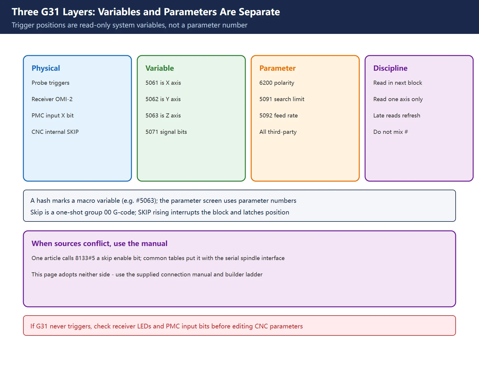
G31 is the skip function, a one-shot G-code in group 00. Its motion is the same as G01, except that it continuously monitors the SKIP signal; when the signal changes from 0 to 1 it interrupts the block, latches the position and skips to the next block. Third-party sources consistently stress two points:
- The trigger position is stored in system variables
#5061(X),#5062(Y),#5063(Z), with#5064–#5066for the 4th / 5th / 6th axes and#5071reflecting the skip signal bits. - Read them in the very next block and transfer the value, for example
G31 Z-50. F300;immediately followed by#100 = #5063;. Reading later risks the variables being refreshed by the decelerated stop position, giving micron-level error; for single-axis probing, read only that axis.
| Layer | Content | Common confusion |
|---|---|---|
| Physical | Probe trigger → receiver (e.g. OMI-2) → PMC input X → CNC internal SKIP | Assuming G31 works as soon as the probe is mounted; receiver and ladder mapping are both required |
| Variable | Read-only system variables #5061–#5063, read inside the program | Confusing them with “parameter number 5063” on the parameter screen |
| Parameter | 6200 polarity, 5091 / 5092 search limit and feed (third-party) | Applying the macro # notation to parameter numbers; the two numbering systems are unrelated |
Table 4 – The three G31 layers and the notation most often confused
One widespread trap must be called out: a long third-party Chinese article describes the setter reference position as “parameter No. 5063, note this is not macro variable #5063“, while also writing #5091 with a hash to mean a parameter number. That article mixes macro variable notation with parameter numbers, so this page does not adopt any of its specific number values. The same article calls 8133#5 a “skip function enable bit”, whereas common parameter tables and our own Fanuc Analog Spindle Commissioning treat 8133#5 as spindle-serial-interface related – the two claims conflict, so verify against the supplied manual and copy neither side.
SKIP polarity, multi-step skip (G31 P) and input addresses such as X4.0 all belong to the builder wiring and the supplied connection manual. When G31 does not trigger, check the receiver status LEDs and whether the PMC input bit follows the probe – do not start by editing CNC parameters. See Fanuc 0i-MD PMC Diagnostic Screens and FANUC Diagnostic Number (DGN) Reference for the screen-side work.
5. G36 / G37 and the Safety Envelope: Do Not Mix Them
G36 and G37 are the automatic tool measurement codes Fanuc provides for tool setters. Both are group 00 and behave like G31 (monitoring SKIP during a feed move), but on trigger they automatically write the computed result into a tool offset, whereas G31 only records the position and does nothing further. Third-party sources give this split:
| Code | Measurement direction | What it writes | If used wrongly |
|---|---|---|---|
| G36 | Radial (X / Y axis) | Geometry or wear offset related to radius / diameter | Using G36 for length writes a value with no length meaning |
| G37 | Axial (Z axis) | Tool length (H offset) | Using G37 for radius produces an unusable result |
Table 5 – The G36 / G37 split (third-party; confirm against the supplied manual)
Those sources also note that G36 / G37 provide no safety fence of their own: the search distance and feed that protect the setter are set by parameters such as 5091 / 5092, and exceeding the search distance without a trigger raises an alarm and stops motion. No official manual text was verified here, so no values are given and this is not an operating instruction. The reliable field practice is to cancel tool length compensation first, confirm a safe height, prove the search distance with a low-feed single-block dry run, and only then run with a tool.
The same diagnostic line as G31 applies: every tool touching one face off by the same constant is a parameter problem; tool-to-tool variation is stylus contact geometry, insert nose radius entry or boring bar deflection. That line saves a great deal of pointless parameter editing.
6. The O9000 Macro Chain: Renishaw Numbers Are Not a Fanuc Standard
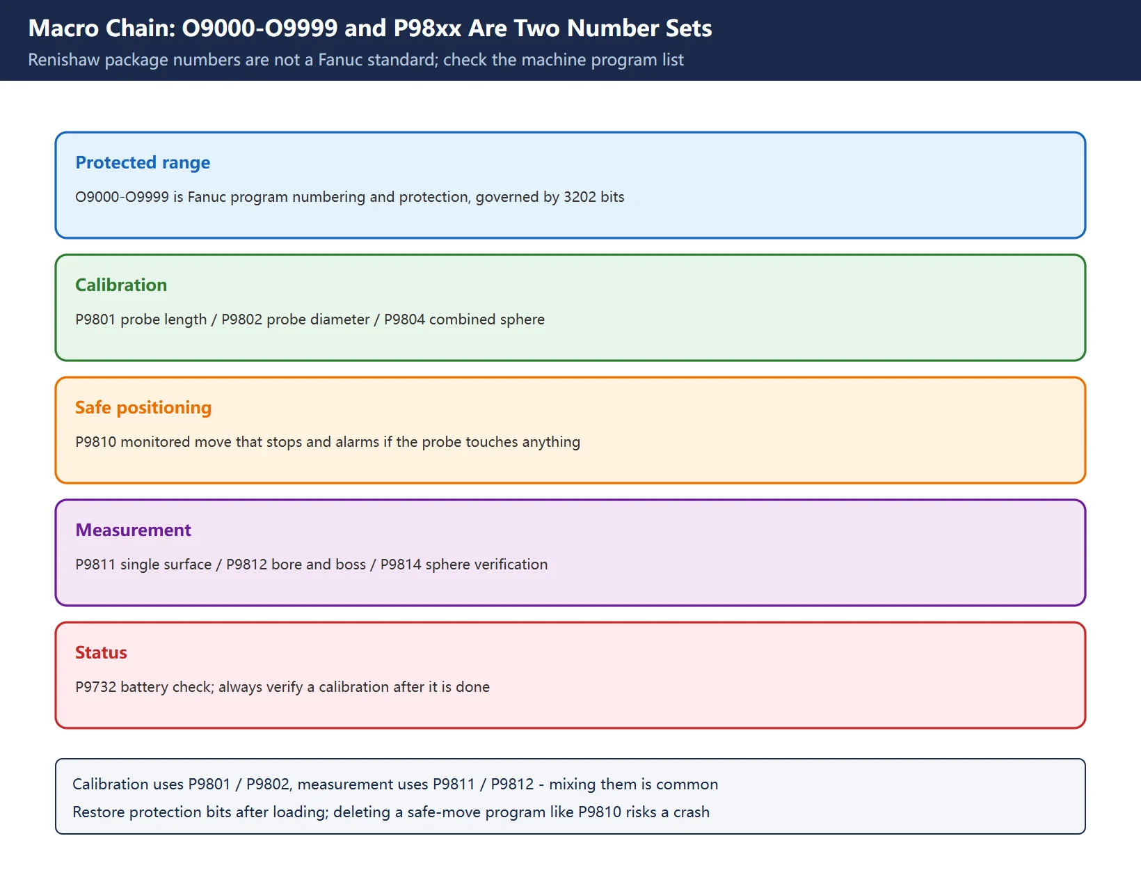
Packages such as Renishaw Inspection Plus wrap G31 into cycles that can be called directly with G65, stored in CNC memory as programs in the O9000–O9999 range. Two numbering systems must be kept apart: O9000–O9999 is Fanuc’s program number range and protection mechanism, while P9801 / P9810 are numbers defined by the macro package, which can differ between builders and package versions.
| Category | Program numbers listed by third-party sources | Purpose |
|---|---|---|
| Calibration | P9801 / P9802 / P9804 | Probe length calibration, probe diameter calibration, combined sphere calibration |
| Safe positioning | P9810 | Monitored move that stops and alarms if the probe touches anything en route |
| Measurement | P9811 / P9812 / P9814 | Single-point surface, bore / boss, sphere verification |
| Status | P9732 | Battery level check |
Table 6 – Macro numbers by purpose (third-party package; verify against the machine program list)
Two further warnings from those sources: calibration uses P9801 / P9802, measurement uses P9811 / P9812, and treating a measurement cycle as calibration is a common mistake; and a calibration must always be verified against a sphere or ring gauge afterwards, otherwise it is like replacing a battery without checking the device actually powers on. On the protected program range, see Fanuc Tool Change Stuck Recovery and FANUC LADDER III Program Protection. A third-party article labels 3202#4 as NE8 and 3202#0 as NEP, which conflicts with common Fanuc bit naming (NE9 protecting O9000-O9999); this page adopts neither bit name and only insists on one rule: restore the protection bits to locked after loading, because an operator accidentally deleting a safe-move program such as P9810 can lead directly to a crash.
For macro variable partitions, G65 calls and nesting limits see Fanuc Macro B Guide; for getting programs into the CNC see FANUC Program Transfer: RS-232, Memory Card, USB, Ethernet, DNC.
7. Three Field Disciplines That Cost the Most When Ignored
- Calibration feed must equal production feed. The trigger is detected at the instant the switch operates, and the overtravel between trigger and stop varies proportionally with feed. Calibrating at 100 mm/min and measuring production tools at 500 mm/min bakes that difference into every compensation value. Position error from electrical delay is a builder- or site-specific figure that must be measured; do not copy millisecond numbers from the web.
- Approach each face from one direction only, so reverse backlash is not folded into the reference.
- Fix the home position before fixing parameters. After a battery swap, encoder replacement or grid shift edit, all four parameters appear wrong simultaneously; the reference point is upstream.
That also answers the frequent question “tool length is still 0.01 mm out after calibration”: do not edit parameters first. Run the five-cycle repeatability check. If the spread is small but the whole group is shifted, check calibration versus production feed, approach direction and face cleanliness, and only then the reference distance parameters.
8. Tool Setter vs Touch Probe vs Gauge Block
| Device | Where its parameters live | Main error source | When to use it |
|---|---|---|---|
| In-machine tool setter (Tool Eye) | Contact-surface reference distances such as 5015-5018, plus each tool's geometry offset | Arm lock, face contamination, approach speed | Batch automatic tool setting on lathes, re-check after tool change |
| Workpiece touch probe | Probe length / radius calibration values held in macro-side variables and offsets | Pre-travel variation (PTV), bent stylus, battery | On-machine measurement, work alignment, sphere verification |
| Gauge block / feeler | Usually no CNC parameter at all; only affects manually entered offsets | Operator feel, contact pressure, block wear | Fallback when no automatic setter is available |
Table 7 – Ownership and error sources (accuracy figures belong to the builder spec and on-site measurement; no generic values here)
Heidenhain is a separate system: iTNC 530 uses MP, TNC 640 / TNC7 use Cfg, and tool measurement runs through TCH PROBE 31 / 481. See Heidenhain Touch Probe Calibration and TCH PROBE 31 / 481 Tool Length Measurement. Brand, command set and parameter family all differ, so never carry Fanuc 5015 over to a Heidenhain control. A Renishaw encoder installation case study is also available in the Chinese-language section of this site.
9. Lookup Keys and an Internal Index
| Lookup key | Question it answers | Where to look |
|---|---|---|
| CNC model + software version | Whether the number exists on this control and who owns it | Supplied parameter manual cover and SYSTEM version screen |
| Manual number + section number (not page number) | Official definition and data type of 5015-5018 | Measurement section of the official additional manual |
| Builder I/O list and ladder | Which X point SKIP lands on, and its polarity | Supplied connection manual, PMC cross-reference |
| Macro program list | Whether P98xx is loaded and protection bits restored | CNC program screen and supplied program list |
Table 8 – Four lookup keys and the question each answers
Related on this site: Fanuc Parameter Number Map by Range · Why Is a Fanuc Parameter Missing? · Fanuc Override Setup · FANUC Parameter Write Protect (PWE) · FANUC Diagnostic Number (DGN) Reference · Fanuc 0i-MD PMC Diagnostic Screens · How to Export / Print FANUC Parameter Tables and Ladder · Fanuc Macro B Guide · Fanuc Tool Change Stuck Recovery · FANUC LADDER III Program Protection · Fanuc G41/G42 Interference Alarm · FANUC MPG Handwheel Signal Chain · SINUMERIK 828D Common Machine Data.
Frequently Asked Questions
What is the difference between parameter 5015 and 5016?
Per the official Fanuc additional manual B-63523EN-1/02, 5015 is the distance from the measurement reference position to the X axis plus contact surface (X1P) and 5016 is the distance to the X axis minus contact surface (X1M); the same table includes 5017 (Z plus face) and 5018 (Z minus face). The widespread “5015 for ID tools, 5016 for OD tools” claim comes from a third-party article whose own language editions contradict each other. Twin-sensor machines also have 5056-5059, valid only when bit 0 (2NR) of 5051 is 1. All four numbers are two-word, signed, with units that follow the increment system, and axes under diameter programming are set using a diameter value. Record the original values and signs before editing, and confirm the supplied manual has not remapped the measurement function.
Why can I not read the position after a G31 trigger?
The most common reason is not capturing it in the next block. Trigger positions are held in read-only system variables #5061 (X) / #5062 (Y) / #5063 (Z); reading later risks those variables being refreshed by the decelerated stop position. The correct pattern is G31 Z-50. F300; immediately followed by #100 = #5063;. The second class of cause is that SKIP never reached the CNC: probe not optically activated, receiver status LED abnormal, ladder not mapping the X input to SKIP, broken shield causing glitches, or low battery – all present as “travels to the endpoint without triggering”. Note that #5061–#5063 are macro variables and parameter numbers are a separate numbering system; polarity and addresses must be confirmed against the supplied connection manual and builder I/O list.
Tool length is still 0.01 mm out after calibration – parameters or something else?
Do not edit parameters first. Start with repeatability: run five measurement cycles on one tool without touching anything. Spread above 0.01 mm means a mechanical issue (stylus locknut, arm lock, chips and coolant film on the face, drag-chain cable) that no parameter edit will fix. If the spread is small but the group is shifted consistently, check three things in order: whether calibration and production approach feeds match (overtravel scales with feed), whether every face is approached from one direction only (reverse approach adds lost motion), and whether the home position moved after a battery replacement or grid shift edit. Only then consider the 5015-5018 reference distances, and verify each against the supplied manual – never trial-edit without a recorded rollback.
Last updated: 2026-11-15
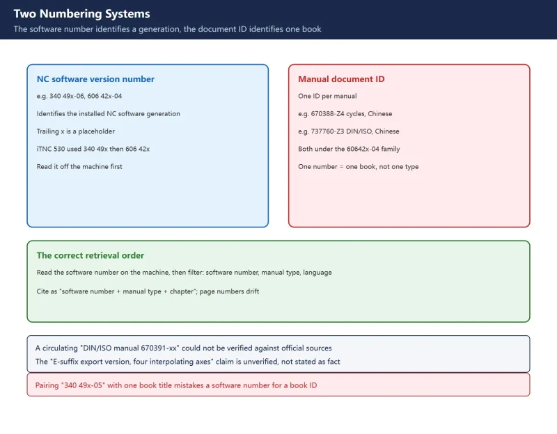
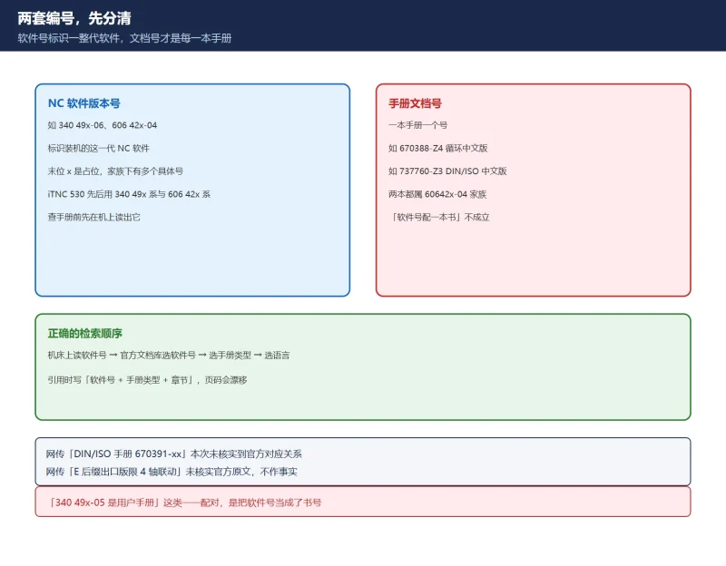
Beyond tool setter calibration: verify the option legend in the supplied sheet
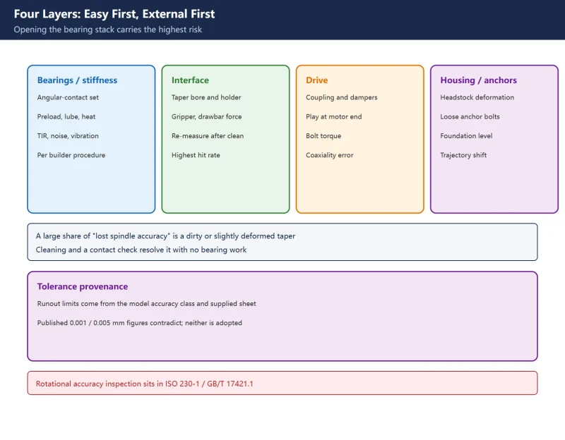
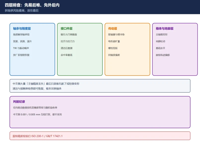
Beyond probe calibration: where spindle rotational accuracy fits
Where to go next
- FANUC Troubleshooting — the full guide library: alarms, diagnosis numbers, servo, spindle, PMC and electrical faults, organised by symptom.
- CNC Repair Tools — which instrument measures what: multimeters, clamp meters, insulation testers and oscilloscopes, with the specification that actually matters.
- Remote Technical Support — have the readings reviewed with you: alarm reverse lookup, PMC ladder analysis and servo tuning advice by call. Repair companies and integrators welcome.
Read the guide, get the right instrument, or walk the diagnosis through with someone — pick whichever you need.
The original Chinese version — same procedure, with the full field notes.

















暂无评论内容