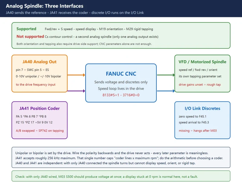



Bottom line: when an analog spindle will not behave, the cause is almost always one of three things – 3730 (gain) and 3731 (offset) applied the wrong way round, 8133#5 left at 0 so the control keeps looking for a serial spindle, or the A/B phases on JA41 reversed so the one-rotation direction is inverted. None of these produces a clean alarm. They show up as a speed that is off by a fixed ratio, a slow drift at low speed, or SP742 the moment you try to rigid tap.
A VFD-driven spindle (usually called an analog spindle) is a half-open arrangement on a Fanuc control. The CNC outputs a 0-10V reference and a handful of discrete signals; the actual speed loop, acceleration ramps and orientation all live in the drive. That is why the method is completely different from a serial spindle: with a serial spindle you tune the CNC side; with an analog spindle you align the two sides.
1. Know the capability boundary first
Before choosing this route, look at the table. The line between what an analog spindle can and cannot do is sharp, and most failed projects picked the wrong architecture at the start.
| Function | Supported on analog spindle | Precondition |
|---|---|---|
| Forward/reverse and S-command speed control | Yes | Basic function, needs only the JA40 voltage output |
| Spindle speed display | Yes | Position coder on JA41 plus a correct pulse count in 3720 |
| Spindle orientation (M19) | Yes | The drive itself must support orientation and the JA41 coder must be healthy |
| Rigid tapping (M29) | Yes | Drive must support a rigid tapping mode, G61.0 must be routed through the PMC, and the coder line count must be sufficient |
| Cs contour control | No | Requires a serial spindle |
| More than one analog spindle | No | One control has only one analog output channel |
The hard limit: Fanuc provides one analog output. A machine can therefore have at most one analog spindle. If there are two spindles, the second must be serial. Separately, the JA41 port has a maximum input frequency of roughly 256 kHz, which caps the product of encoder line count and maximum speed – see the worked figures in section 5.
2. Wiring: three interfaces, do not cross them
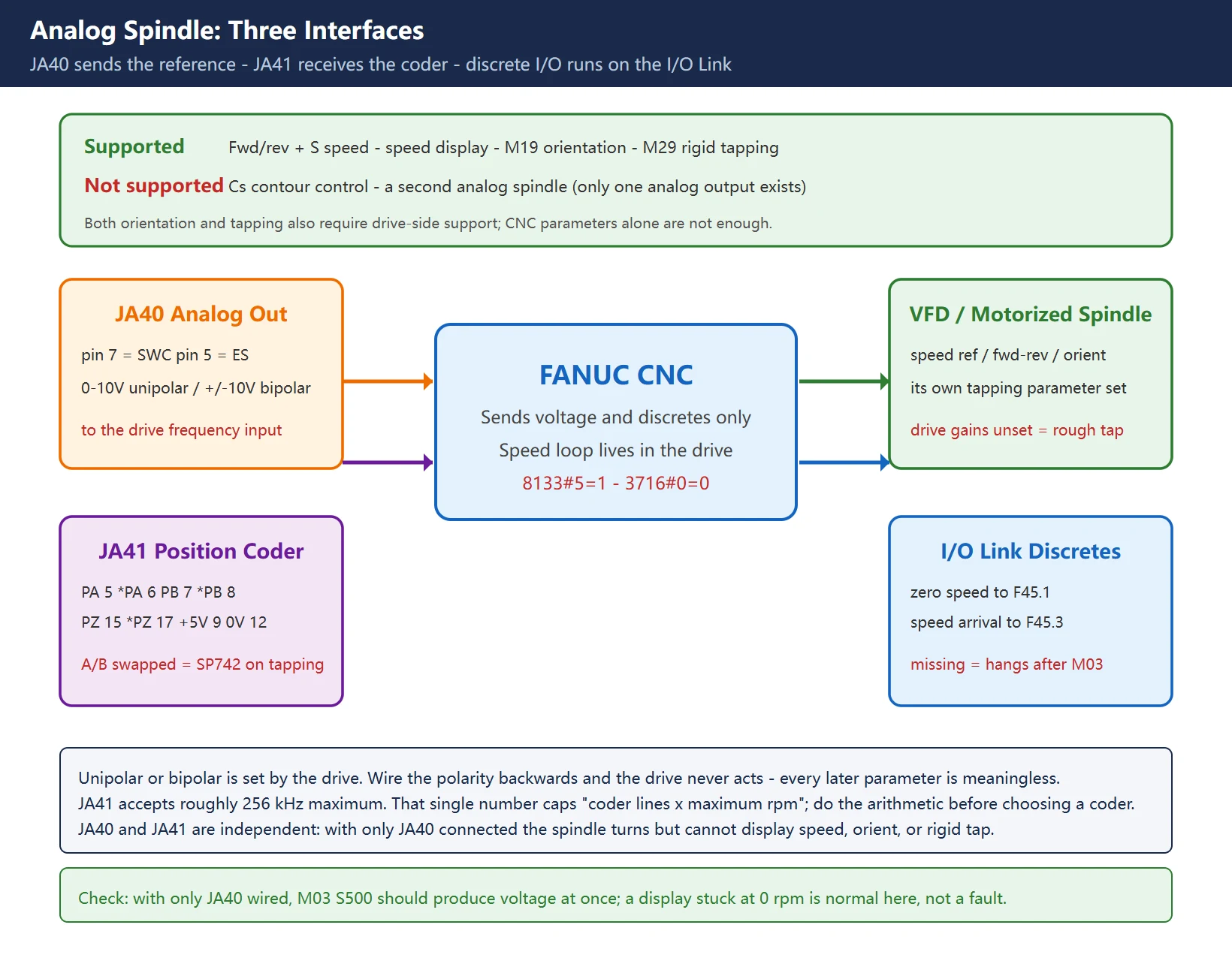
| Interface | Purpose | Key pins | Common mistake |
|---|---|---|---|
JA40 | 0-10V (or +/-10V) reference to the drive frequency input | SWC (pin 7), ES (pin 5), ENB1 (8), ENB2 (9) | Polarity reversed on a unipolar hookup so the drive never changes speed; ENB1/ENB2 miswired |
JA41 | Spindle position coder input (differential A/B/Z) | PA(5) *PA(6) PB(7) *PB(8) PZ(15) *PZ(17) +5V(9/18/20) 0V(12/14/16) | A and B swapped so the displayed direction is inverted and tapping trips SP742; shield not single-point grounded |
JD1A/JD51A | I/O Link for discrete signals (forward, reverse, zero speed, alarm, orientation done) | Per the I/O unit | Zero-speed and speed-arrival not routed back to F45.1 / F45.3, so the control believes the spindle never turns |
On polarity, JA40 has two legitimate uses:
- Unipolar: output is 0 to +10V only; direction comes from the drive’s forward/reverse discrete inputs. Wire the polarity backwards and the drive does nothing at all.
- Bipolar: output is -10V to +10V and the sign carries direction. This saves two discrete outputs, but the drive must accept a bipolar reference – many general-purpose VFDs do not and need an interface board.
Confirm which mode the drive expects before wiring JA40. Get this wrong and no amount of parameter work will help.
3. The enable chain: four steps, in this order
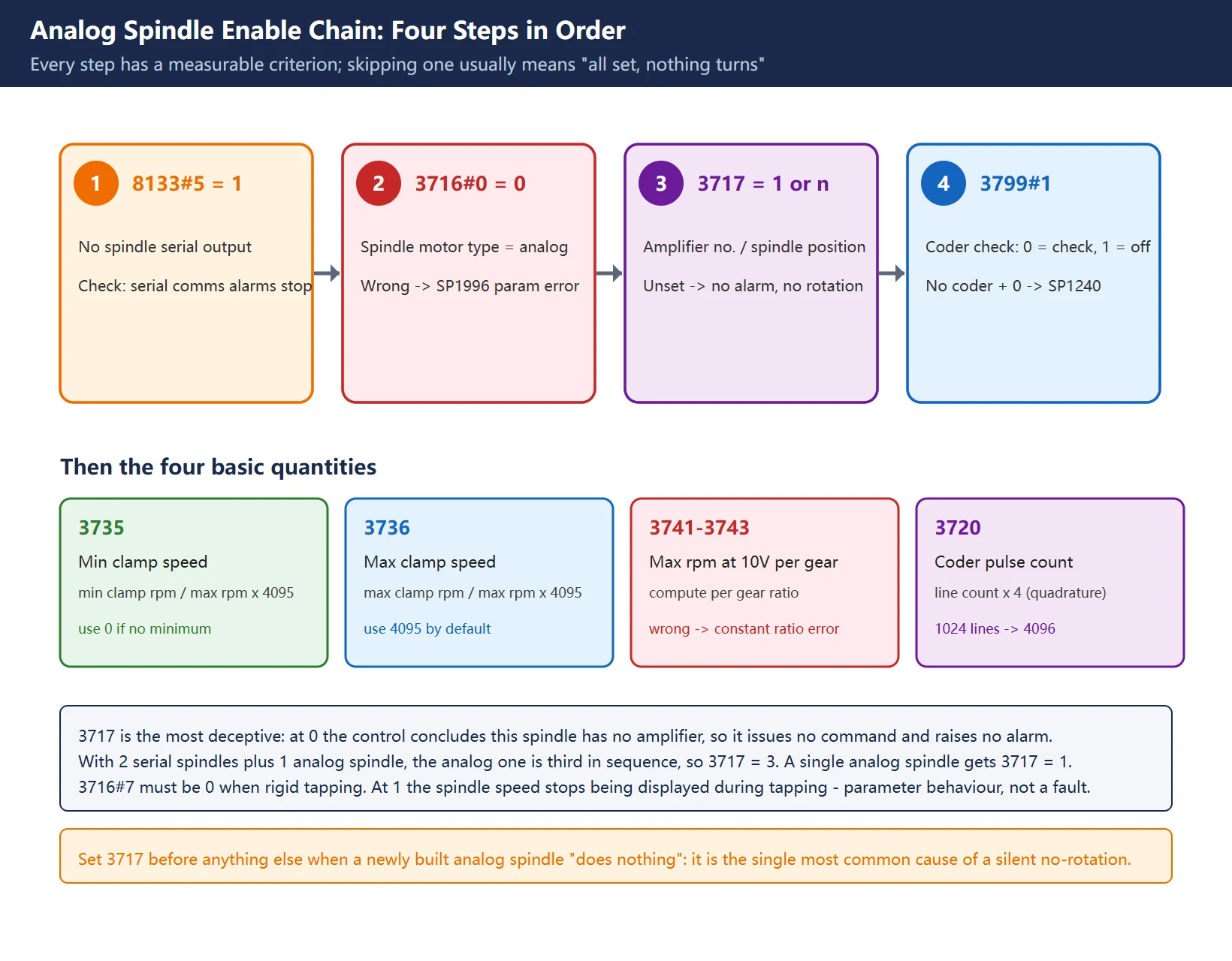
The enable parameters must be set in sequence. Skip one and the symptom is “everything is set but the spindle does not turn”.
| Step | Parameter | Value | Purpose | Consequence if wrong |
|---|---|---|---|---|
| 1 | 8133#5 | 1 | Do not use spindle serial output | Left at 0 the control still tries to talk to a serial spindle amplifier, producing communication alarms and no spindle command |
| 2 | 3716#0 (A/Ss) | 0 | Spindle motor type: 0 = analog, 1 = serial | Wrong setting raises SP1996 (spindle parameter setting error) |
| 3 | 3717 | 1 | Spindle amplifier number for each spindle; for an analog spindle, its position in the spindle sequence | Unset or wrong: no alarm at all, and the spindle simply never turns – the worst failure mode here |
| 4 | 3799#1 | see below | Whether to check the analog spindle position coder for disconnection | Left at 0 with no coder fitted raises SP1240 (position coder disconnected) |
On 3717, the official wording is to set the analog spindle in the spindle configuration. The rule: with N spindles in the system, enter the analog spindle’s position in the spindle sequence. Two serial spindles plus one analog spindle means the analog one is third, so 3717 = 3. A single analog spindle gets 3717 = 1.
On 3799#1 (0 = check for disconnection, 1 = do not check):
- No position coder fitted (speed control only, no orientation or tapping): must be 1, otherwise SP1240 appears at power-up.
- Coder fitted: set 0 and keep the disconnection check. It is a genuine safety feature that catches a broken coder cable; do not leave it disabled just to silence an alarm.
Then the three basic quantities:
| Parameter | Meaning | How to set it |
|---|---|---|
3735 | Spindle motor minimum clamp speed | = minimum clamp rpm / motor max rpm x 4095; use 0 unless a minimum is required |
3736 | Spindle motor maximum clamp speed | = maximum clamp rpm / motor max rpm x 4095; use 4095 unless a lower ceiling is required (M-series systems usually need 4095 entered explicitly) |
3741–3743 | Spindle speed corresponding to 10V, per gear | With a gearbox, compute per gear ratio; with a single range, enter the spindle maximum speed directly |
The classic symptom of a wrong 3741 is a speed that differs from the commanded S value by a constant ratio, because the voltage is linear in S and 3741 defines how many rpm correspond to full-scale voltage. Get that reference wrong and the whole curve is scaled.
3720 is the position coder pulse count = line count x 4 (quadrature). A 1024-line coder gives 4096. If this is wrong the displayed speed is scaled while the actual speed stays correct.
4. Calibrating 3730 and 3731: two formulas, one order
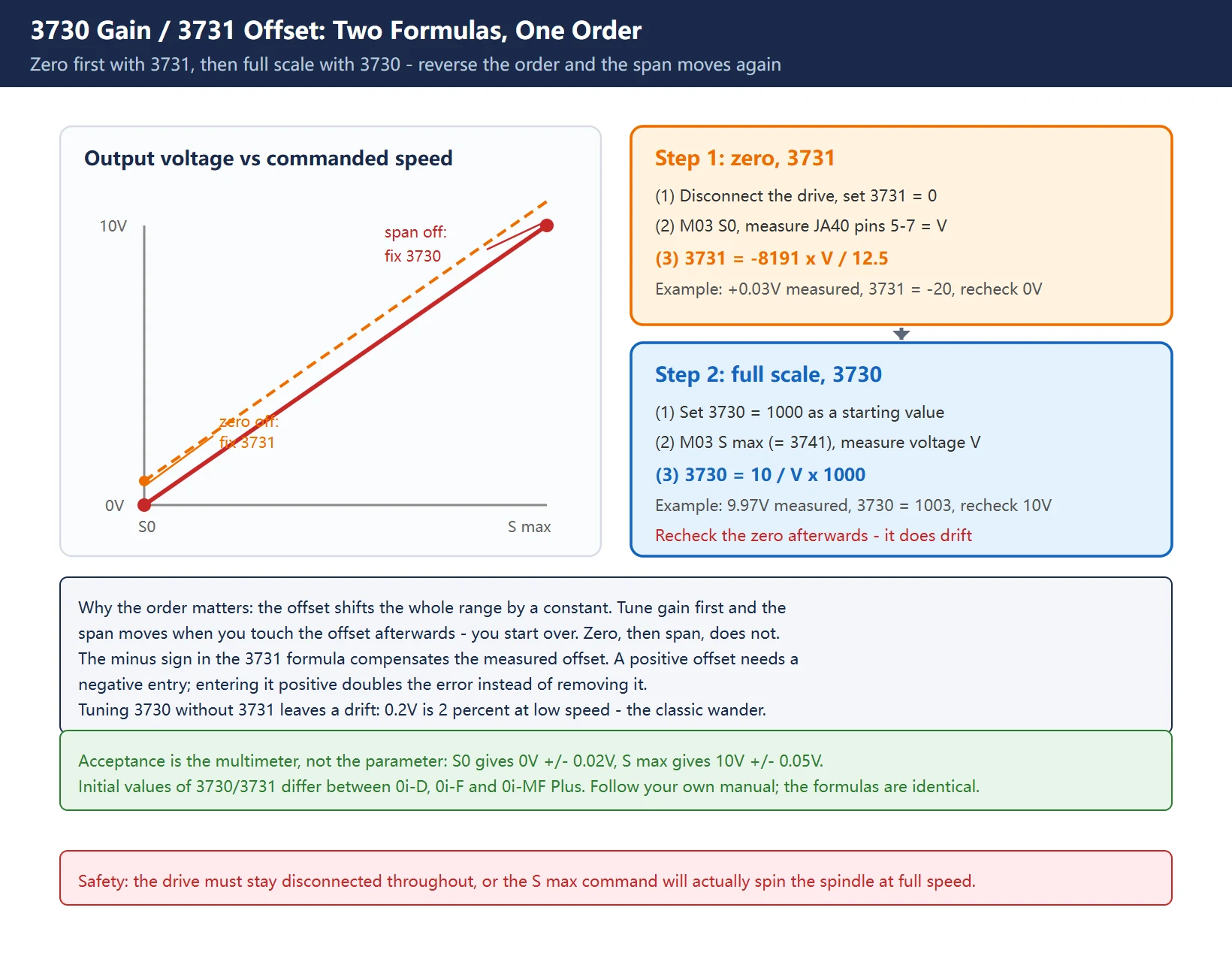
This is the only step that genuinely requires a multimeter, and the one most often applied backwards.
Separate the two jobs clearly:
3731= offset compensation for the spindle analog output. It governs whether the output is 0V at S0 – the zero point.3730= gain adjustment data for the spindle analog output. It governs whether the output is 10V at maximum speed – the full scale.
The order must be 3731 first, then 3730. The reason is straightforward: the offset is a constant shift across the whole range. Tune the gain first, then change the offset, and the full-scale point moves again and you start over. Zero first, span second, and the two steps do not interfere.
Procedure:
- Disconnect the drive (pull the analog input terminals or drop the drive enable) so the motor cannot actually spin.
- Set
3731 = 0and3730 = 1000(standard values) as a starting point. - Command
M03 S0and measure the voltage between pins 5 and 7 of JA40 with a multimeter. Call it Voffset. - Compute
3731 = -8191 x Voffset/ 12.5. For example, measuring +0.03V gives3731 = -8191 x 0.03 / 12.5, about -20. - Write
3731, commandM03 S0again and confirm the output is near 0V. - Command
M03 S(the value in3741) and measure the voltage. Call it Vspan. - Compute
3730 = 10 / Vspanx 1000. For example, measuring 9.97V gives3730, about 1003. - Write
3730, commandM03 Sagain and confirm the output is near 10V. - Reconnect the drive and verify under real load.
Two common traps:
- Doing only one half. Adjusting
3730without3731leaves a zero error; even 0.2V is 2 percent at low speed, which shows up as a speed that will not settle and drifts left and right. - Getting the sign wrong. The formula for
3731carries a minus sign because the compensation acts against the measured offset. A positive measured offset needs a negative value; entering it positive doubles the error instead of removing it.
Note: the standard initial values of
3730and3731differ between models (0i-D, 0i-F, 0i-MF Plus). Some ship with3730 = 1000and3731 = 0; some field references quote 960 for3730. Use the parameter manual for your control, but the calibration formulas are the same. The only acceptance criterion is the measured 0V and 10V – not the parameter value itself.
5. Coder selection: the 256 kHz ceiling
The JA41 port accepts roughly 256 kHz. The pulse frequency from a coder is:
f = line count x rpm / 60
So for a given line count the displayable maximum speed is fixed:
| Coder lines | 3720 (lines x 4) | Displayable max speed | Verdict |
|---|---|---|---|
| 512 | 2048 | 60 x 256000 / 512 = 30000 rpm | Speed is fine, but 512 lines is not enough resolution for rigid tapping |
| 1024 | 4096 | 60 x 256000 / 1024 = 15000 rpm | Tapping is fine, but the display misbehaves above 15000 rpm |
| 2048 | 8192 | 60 x 256000 / 2048 = 7500 rpm | High-precision tapping, low speed ceiling |
This is where the classic conflict comes from: a 24000 rpm high-speed spindle and rigid tapping cannot both be fully satisfied under the 256 kHz limit. Choose 512 lines and the full speed range displays but tapping accuracy is insufficient; choose 1024 lines and tapping works but the display becomes unstable above 15000 rpm.
Practical rule:
- If the display is wrong but the actual speed is correct and rigid tapping executes normally, leave 1024 lines alone and tell the operator that above 15000 rpm the displayed value is not trustworthy and the drive panel should be used instead.
- If the process truly requires precision tapping above 15000 rpm, this route is not viable and a serial spindle is the answer.
One more point that is easily missed: 3716#7 controls whether the spindle position coder pulse count is changed. Set it to 0 when rigid tapping, because setting it to 1 stops the spindle speed being displayed during tapping. That is parameter behaviour, not a fault, but it routinely sends people on a long wild-goose chase.
6. The PMC side: half of an analog spindle lives in the ladder
The CNC supplies a voltage; everything else is the PMC tying the two sides together. Without this, correct parameters produce no function.
| Direction | CNC-side signal | Meaning | Connects to drive |
|---|---|---|---|
| CNC to PMC | G70.6 (orientation command) | Set on M19 | Drive orientation start input |
| CNC to PMC | G70.2 / G70.3 (CTH2A / CTH1A) | Gear selection (with a gearbox) | Gear change solenoids |
| CNC to PMC | G70.0 / G70.1 (SFR / SRV) | Spindle forward / reverse command | Drive forward / reverse terminals |
| CNC to PMC | G61.0 | Rigid tapping signal | Drive rigid tapping mode input |
| CNC to PMC | G33.7 | Spindle override source: 0 = CNC, 1 = PMC | Decides who owns the override |
| PMC to CNC | F45.1 | Spindle zero speed detect | Drive zero-speed output |
| PMC to CNC | F45.3 | Spindle speed arrival | Drive speed-arrival output |
| PMC to CNC | F45.7 | Spindle orientation complete | Drive orientation-done output |
| PMC to CNC | F34.0 / F34.1 | Gear select feedback (GR10 / GR20) | Gear confirm switches |
The three most frequently missed:
- F45.1, F45.3 and F45.7 must be routed back. Without them the control believes the spindle never reaches speed, so the block after M03 waits indefinitely, or auto mode never advances. Check by commanding M03 S500 and watching
F45.3on the PMC signal screen. - G29.6 (*SSTP spindle stop) must stay at 1. It is an active-low, emergency-class signal. Omit it or invert the logic in the ladder and the spindle never moves.
- G61.0 must be synchronous with G28.1 for rigid tapping.
G61.0puts the drive into tapping mode;G28.1switches to the tapping-specific gear range defined by3742. If they are not synchronised the tapping voltage curve still uses the normal cutting range and the error cannot be brought down.
On G33.7: this signal decides whether the spindle override (50/100/120 percent) is controlled by the CNC or the PMC. The usual arrangement is CNC in AUTO/MDI (G33.7 = 0) and PMC in JOG/HAND (G33.7 = 1). Leaving it entirely to the CNC also works, but then the operator will find the override has no effect in manual mode.
7. Five high-frequency failure points
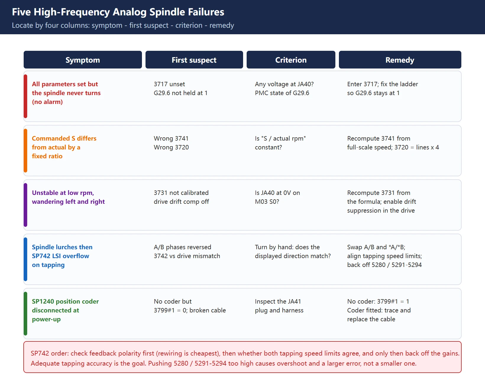
| Symptom | First suspect | Criterion | Remedy |
|---|---|---|---|
| Parameters set but the spindle does not turn at all, no alarm | 3717 unset, or G29.6 not held at 1 | Is there any voltage at JA40? Check PMC state of G29.6 | Enter 3717; fix the ladder |
| Commanded S differs from actual speed by a fixed ratio | Wrong 3741 or wrong 3720 | Is “S / actual rpm” constant? | Recompute 3741 from full-scale speed; recompute 3720 from lines x 4 |
| Unstable speed at low rpm, drifting left and right | 3731 not calibrated, or drive drift compensation off | Is JA40 at 0V on M03 S0? | Recompute 3731 from the formula; enable drift suppression in the drive |
| Spindle lurches then trips SP742 (LSI overflow) during tapping | A/B phases reversed on JA41; 3742 inconsistent with the drive tapping limit; 5280 and 5291–5294 too high | Rotate the spindle by hand and check the displayed direction against reality | Swap A with B and *A with *B; align the two tapping speed limits; back off the gains |
| SP1240 (position coder disconnected) at power-up | No coder fitted but 3799#1 = 0; or a broken cable | Inspect the JA41 plug and harness | Set 3799#1 = 1 if no coder; otherwise trace the cable |
On SP742: this is the most common and most frustrating alarm when an analog spindle is asked to rigid tap (rigid tapping alarm, LSI overflow). Its essence is that the spindle cannot follow the command, so the error accumulates until it overflows. Work three layers in order:
- Feedback polarity (wiring layer). Reversed A/B means the control sees the opposite rotation direction and the error explodes immediately. Check this first – rewiring is the cheapest fix.
- Speed-limit mismatch (parameter layer).
3742on the CNC side and the drive-side rigid tapping maximum speed must agree. A factor-of-two difference guarantees overflow somewhere in the middle of the range. - Excessive gain (tuning layer). Pushing
5280(rigid tapping position loop gain) and5291–5294(spindle loop gain multiplier) high to reduce tapping error actually makes the control overshoot and increases the error. Tapping accuracy should be adequate, not maximal.
Also remember the drive needs its own tapping mode. Most VFDs have a dedicated rigid tapping gain group (speed loop proportional gain, integral time, position loop proportional gain, accel/decel times). Without those set, no amount of CNC-side tuning will hold. On the CNC side, shrinking 5261–5264 (tapping accel/decel time constants) reduces error, but go too far and you trip SP742 directly because the commanded acceleration exceeds what the system can deliver.
8. Acceptance checklist
Walk this list at the end of commissioning. It is done only when every line passes:
M03 S0gives 0V +/- 0.02V at JA40M03 Sgives 10V +/- 0.05V at JA40M04runs reverse and the displayed direction matches the physical direction- Turn the spindle by hand: display error under 1 percent
- Measure five points from minimum to maximum speed: linearity deviation under 2 percent
M19orientation, five repeats, deviation within process tolerance- Rigid tapping test cut with DGN 453 close to 1 (no SP0741)
- All parameters survive a power cycle (
3799#1and friends are not reset)
Item 7 is the core rigid tapping criterion; the full treatment is in Fanuc rigid tapping parameters explained and the lookup table is at Fanuc rigid tapping parameter chart. Note that analog spindle voltage calibration and serial spindle gain tuning are two different bodies of knowledge – do not mix them.
Frequently Asked Questions
Can an analog spindle rigid tap?
Yes, subject to three conditions being true at once: the drive itself supports a rigid tapping mode (with its own tapping parameter group), a position coder is connected to JA41, and the coder line count is sufficient (1024 lines is the practical minimum). Without all three, only floating-holder (synchronous-free) tapping is possible. Note also that G61.0 must be set by the PMC and the gear range switched at the same time.
Why does the spindle not turn at all with no alarm when 3717 is unset?
Because 3717 defines which spindle amplifier this spindle belongs to. At 0 the control concludes the spindle has no amplifier, so it never issues a spindle command and does not regard the configuration as invalid – hence no alarm. This is the single biggest time sink in analog spindle work; check it first whenever “all parameters are set but nothing turns”.
Which one is zero and which is full scale, 3730 or 3731?
3731 is the zero point (whether the output is 0V at S0); 3730 is full scale (whether the output is 10V at maximum speed). A useful mnemonic: the larger number handles the larger voltage. Calibrate 3731 first and 3730 second, because the offset is a constant shift across the range and adjusting it afterwards pulls the full-scale point off again.
Last updated: 2026-10-31
Where to go next
- FANUC Troubleshooting — the full guide library: alarms, diagnosis numbers, servo, spindle, PMC and electrical faults, organised by symptom.
- CNC Repair Tools — which instrument measures what: multimeters, clamp meters, insulation testers and oscilloscopes, with the specification that actually matters.
- Remote Technical Support — have the readings reviewed with you: alarm reverse lookup, PMC ladder analysis and servo tuning advice by call. Repair companies and integrators welcome.
Read the guide, get the right instrument, or walk the diagnosis through with someone — pick whichever you need.
The original Chinese version — same procedure, with the full field notes.















暂无评论内容