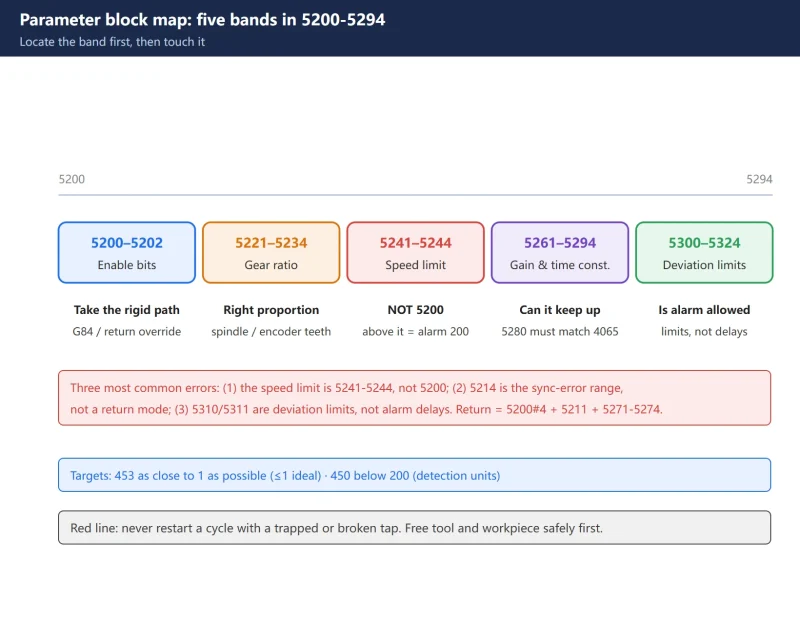



Preconditions: confirm the encoder configuration (absolute/incremental, direct or geared) and the number of spindle gears. On a geared spindle, 5221–5224 / 5231–5234 / 5241–5244 are per gear – fill all four.
This table only maps “parameter number → meaning → typical value”. It does not replace your machine builder’s parameter manual. Back up before changing, and change one group at a time.
1. How to use this table
Three rules matter more than the numbers:
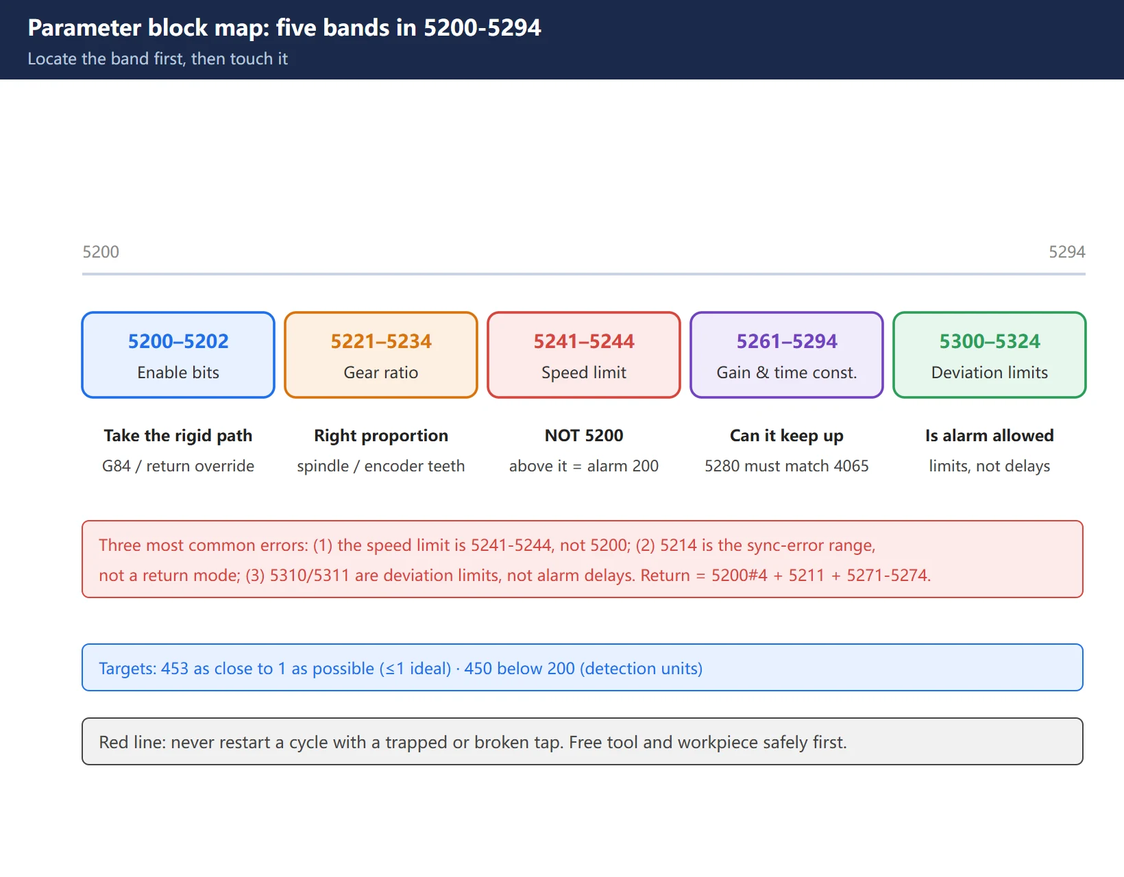
- Classify first. 5200–5294 is not a pile of isolated parameters – it is five blocks: enable bits, gear ratio, speed limit, gains and time constants, deviation limits. Decide which block your symptom belongs to before touching anything.
- Read the diagnostics before editing parameters. Run in air and look at 452/453 to decide whether to change gain or time constant – do not tune by feel.
- Change one group at a time. Change gain, time constant and deviation limit together and you can no longer tell what did what.
2. Parameter blocks (5200–5294)
2.1 Enable bits: 5200–5202
| Param | Name | Meaning | Typical |
|---|---|---|---|
| 5200#0 | G84 | 0 = G84 ordinary (floating) tapping; 1 = G84 rigid by default | 0 during commissioning, 1 when stable |
| 5200#1 | VGR | Arbitrary gear ratio between spindle and encoder allowed | Match the mechanics |
| 5200#2 | CRG | Rigid tapping cancel method | Per builder |
| 5200#4 | DOV | Feed override effective during return | 0 on automated lines |
| 5200#5 | PCP | High-speed chip-clearing tapping cycle | Enable for deep holes |
| 5200#6 | FHD | Feed hold / single block effective in rigid tapping | As needed |
| 5200#7 | SRS | Which spindle performs rigid tapping (multi-spindle) | N/A single spindle |
| 5201#0 | NIZ | Smoothing control in rigid tapping | As needed |
| 5201#2 | TDR | Cutting-constant selection | As needed |
| 5202#0 | ORI | Spindle orientation on entering the cycle | Enable for deep holes |
2.2 Gear ratio: 5221–5224 / 5231–5234
| Param | Meaning |
|---|---|
| 5221–5224 | Rigid tapping spindle-side tooth count (gear 1–4) |
| 5231–5234 | Rigid tapping position-encoder-side tooth count (gear 1–4) |
Ratio = encoder-side teeth / spindle-side teeth.
Directly coupled encoder (1:1) → set both sides equal. Re-check after changing a pulley or rebuilding the spindle – a wrong value raises no alarm, it just tears threads consistently.
2.3 Speed limit: 5241–5244
| Param | Meaning | Note |
|---|---|---|
| 5241–5244 | Rigid tapping spindle maximum speed (gear 1–4) | Exceeding it → alarm 200 (illegal S code) |
⚠️ Not 5200. This is the most widely repeated error.
2.4 Gains and time constants
| Param | Meaning | Key point |
|---|---|---|
| 5280 | Rigid tapping position loop gain (common) | Shared by spindle and tapping axis |
| 5281–5284 | Same, per gear | Active when 5280 is 0 |
| 5291–5294 | Gain multiplier per gear | As needed |
| 4065–4068 | Rigid tapping spindle-side loop gain | Must equal 5280 / 5281–5284 |
| 5261–5264 | Entry accel/decel time constant | Increase for stainless / deep holes |
| 5271–5274 | Return accel/decel time constant | Tune here if retract misbehaves |
| 4099 | Motor excitation settling delay | Auto-set |
2.5 Deviation limits and in-position width
| Param | Meaning |
|---|---|
| 5300 / 5301 | In-position width, tapping axis / spindle |
| 5310 | Tapping axis deviation limit during motion |
| 5311 | Spindle deviation limit during motion |
| 5312 | Tapping axis deviation limit at stop |
| 5313 | Spindle deviation limit at stop |
| 5314 | Tapping axis movement deviation limit |
| 5321–5324 | Spindle backlash per gear |
| 5214 | Rigid tapping sync-error range setting |
⚠️ 5310/5311 are not alarm delays – they are deviation limits. Too large and they stop protecting you; too small and you get spurious SP0741.
⚠️ 5214 is not a “return mode”. Return involves 5200#4 + 5211 + 5271–5274.
3. DGN 452 / 453 / 450 / 451
| 5204#0 | DGN | Meaning | Unit |
|---|---|---|---|
| 1 | 452 | Instantaneous sync error (positive = spindle leads) | % |
| 1 | 453 | Maximum sync error (held to next cycle) | % |
| 0 | 450 | Instantaneous error | detection units |
| 0 | 451 | Spindle motion pulses | detection units |
Targets (field values; defer to the builder spec):
- 453 as close to 1 as possible (≤1 ideal, ≤10% commonly tolerated)
- 450 below 200 (detection units)
Reading split:
- 452 non-zero throughout → gain mismatch (check 5280–5284 vs 4065–4068)
- 452 large only in accel/decel → time constant (5261–5264 / 5271–5274)
- 452 large only under load → not a parameter issue; check tap, pilot hole, chips, load
4. SP0741 and its three root-cause directions
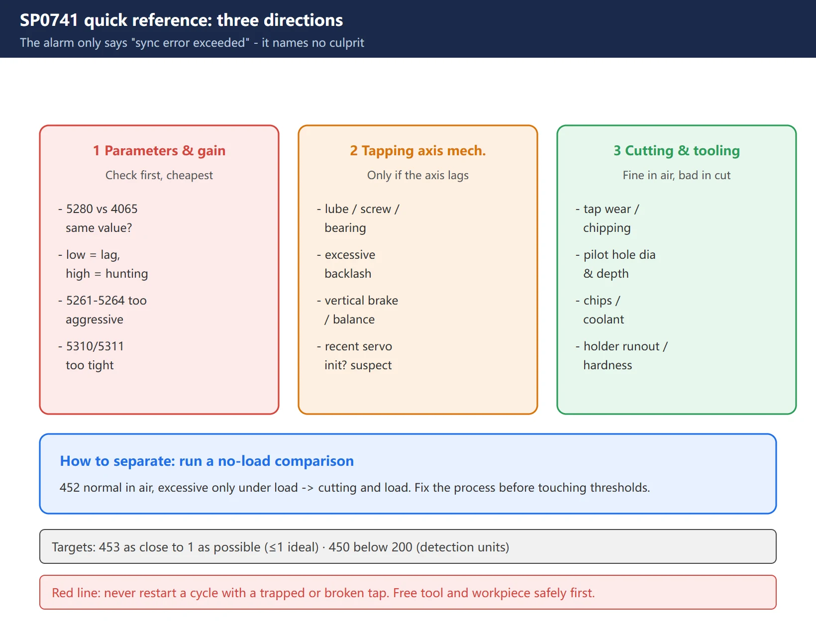
SP0741 / SV0741 = rigid tapping excess error. It only says “sync error exceeded” – it does not name the culprit.
| Direction | What to check |
|---|---|
| 1 Parameters & gain | Is 5280 matched to 4065–4068; gain low (lag) / high (hunting); 5261–5264 too aggressive; 5310/5311 too tight |
| 2 Tapping axis mechanics | Lubrication, ballscrew, bearings, guides, coupling, backlash; vertical brake/counterbalance; holder axial compliance; servo load; suspect recent servo initialization first |
| 3 Cutting & tooling | Tap wear/chipping/geometry/coating; pilot hole diameter and depth; blind-hole clearance; chip evacuation; coolant; holder and collet runout; hardness variation |
How to separate: run a no-load comparison. 452 normal in air and excessive only under load → cutting and load; fix the process before touching thresholds.
5. Related alarms (200 / 201 / 203 / 204 / 205)
| Alarm | Text | Meaning |
|---|---|---|
| 200 | Illegal S command | S outside the 5241/5242 range, or no S; check 5241–5244 |
| 201 | No feed rate | No F specified in the program |
| 202 | Position LSI overflow | Spindle-assigned value too large |
| 203 | Rigid tapping mode not specified | Wrong M29 or S command format |
| 204 | Illegal axis command | An axis move placed between M29 and S |
| 205 | Rigid tapping DI signal off | After M29, G61#0 is not 1; check the ladder |
FAQ
Is 5200 or 5241 the spindle speed limit in rigid tapping?
5241–5244 is the speed limit (gear 1–4), not 5200.
5200 is the enable block: 5200#0 decides whether G84 is rigid by default, 5200#4 decides whether override is effective during return. An S command above the 5241/5242 setting raises alarm 200 (illegal S command). So “it will not go faster / alarms when I raise the speed” means editing 5241–5244.
This confusion is extremely common in Chinese-language material; getting it right first saves a lot of detours.
How do I map SP0741 to a root cause?
SP0741 only says “sync error exceeded” and carries no root-cause information – derive it from the diagnostics:
- Run in air and watch 452: non-zero throughout → check whether 5280–5284 and 4065–4068 hold the same value (gain mismatch is the most frequent cause);
- 452 large only in accel/decel → tune 5261–5264 / 5271–5274;
- Normal in air, large under load → go to tap, pilot hole, chip evacuation, coolant and axis lubrication / ballscrew / coupling.
Hint: if the tapping axis lags while the spindle is fine, raising spindle limit 5311 does nothing – check the axis side.
Is the 5200 block identical across 0i generations?
Broadly yes, but not guaranteed identical. 0i-D / 0i-F / 0i-F Plus and 31i share the same rigid tapping framework (5200 enables, 5221/5231 gear ratio, 5241 speed limit, 5280 gain, 5310 deviation limits), but:
- some features (e.g. 5203#2 feed forward RFF) exist only on newer 0i-F Plus;
- individual parameter numbers may be occupied or subtly redefined between generations;
- twin-spindle machines may have a separate gain group.
Practice: use this table to locate the direction, then confirm the exact number and range against the parameter manual for your control. This is a locator, not a substitute for the manual.
Last updated: 2026-10-31
Read next: Fanuc rigid tapping parameters explained: M29/G84 sync and the 5200-5294 chain — this page is the lookup table; that one explains why each block is set the way it is, the commissioning order, and the five common mistakes.
Related: Classifying homing failures — if the Z axis stops at a different place every cycle, rule out homing and the reference position before coming back to 5200-5294.
Related: Reading CNC electrical schematics — the spindle encoder circuit and gear-ratio wiring have to be right before 5221-5224 / 5231-5234 mean anything.
Where to go next
- FANUC Troubleshooting — the full guide library: alarms, diagnosis numbers, servo, spindle, PMC and electrical faults, organised by symptom.
- CNC Repair Tools — which instrument measures what: multimeters, clamp meters, insulation testers and oscilloscopes, with the specification that actually matters.
- Remote Technical Support — have the readings reviewed with you: alarm reverse lookup, PMC ladder analysis and servo tuning advice by call. Repair companies and integrators welcome.
Read the guide, get the right instrument, or walk the diagnosis through with someone — pick whichever you need.
The original Chinese version — same procedure, with the full field notes.











暂无评论内容