


In most cases the problem is not the program. It is that nobody has properly understood what this parameter group controls. Parameter tables circulating online are heavily copy-pasted and contain real errors – the spindle speed limit is commonly attributed to 5200, 5214 is described as a “return mode”, and “5201/5202 feed per revolution” simply does not exist. Copying those tables is how machines get worse.
This article follows the order principle → parameter chain → diagnostics → alarm troubleshooting, explains what the 5200–5294 group actually does, and corrects several widespread misconceptions along the way.
One line: rigid tapping is nothing more than strict linear sync between spindle rotation and feed travel (P = F / S). Every parameter serves that one relation – enable bits decide whether you take this path, gear ratios decide whether the proportion is right, gains and time constants decide whether the axis can keep up, and deviation limits decide whether an alarm is allowed.
1. Rigid tapping vs floating tapping: why phase sync is mandatory
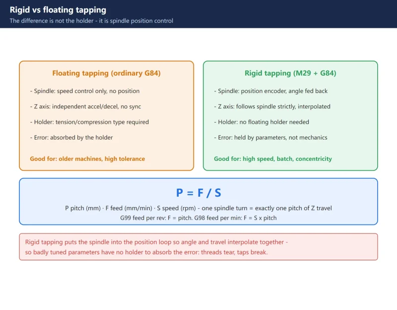
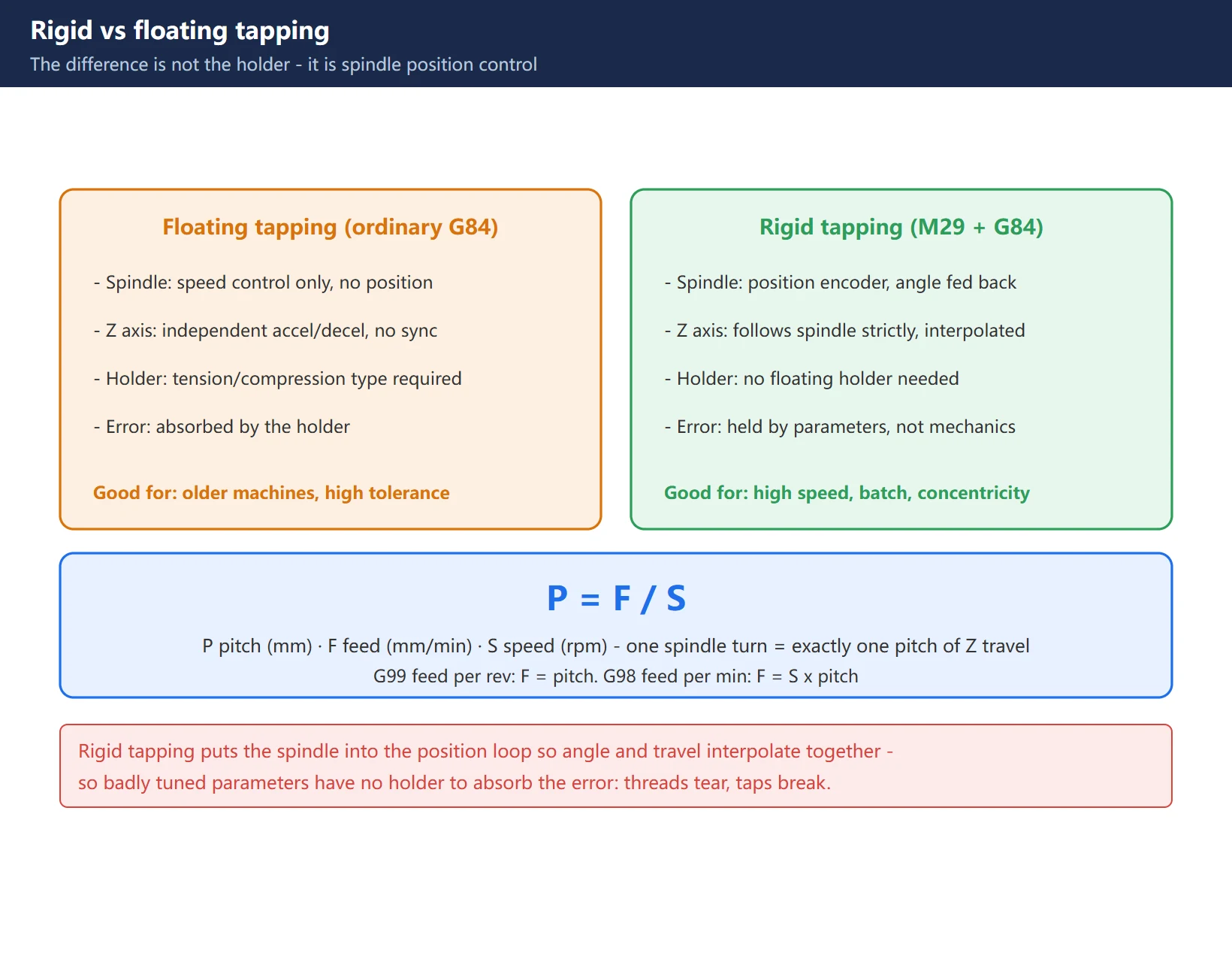
The difference is not the price of the holder – it is whether the spindle has position control.
| Floating tapping (ordinary G84) | Rigid tapping (M29 + G84) | |
|---|---|---|
| Holder | Tension/compression tapping holder required | Not required; a rigid holder works |
| Spindle | Speed control only, no position control | Spindle carries a position encoder, rotation angle fed back in real time |
| Sync | Spindle and Z may differ in speed; the holder absorbs the error | Z servo follows spindle angle strictly, linear interpolation |
| Programming | G84 ... F__ | M29 S__; or same block G84 ... M29 S__; |
| Advantage | Tolerant, works on old machines | Higher speed, better thread concentricity, suited to batch and automation |
| Weakness | Chatter at high speed, limited thread finish | Badly tuned parameters tear threads and break taps |
There is exactly one core relation:
P = F / S
- P: thread pitch (mm)
- F: tapping axis feed (mm/min)
- S: spindle speed (rpm)
In other words, one spindle revolution must equal exactly one pitch of Z travel. In ordinary tapping the spindle and Z decelerate and reverse independently, so that relation is hard to hold at the bottom of the hole – which is why a floating holder exists. Rigid tapping puts the spindle into the position loop so rotation and travel interpolate together; the error is no longer absorbed mechanically, it is held by parameters.
2. The must-set parameters: what 5200–5294 actually control
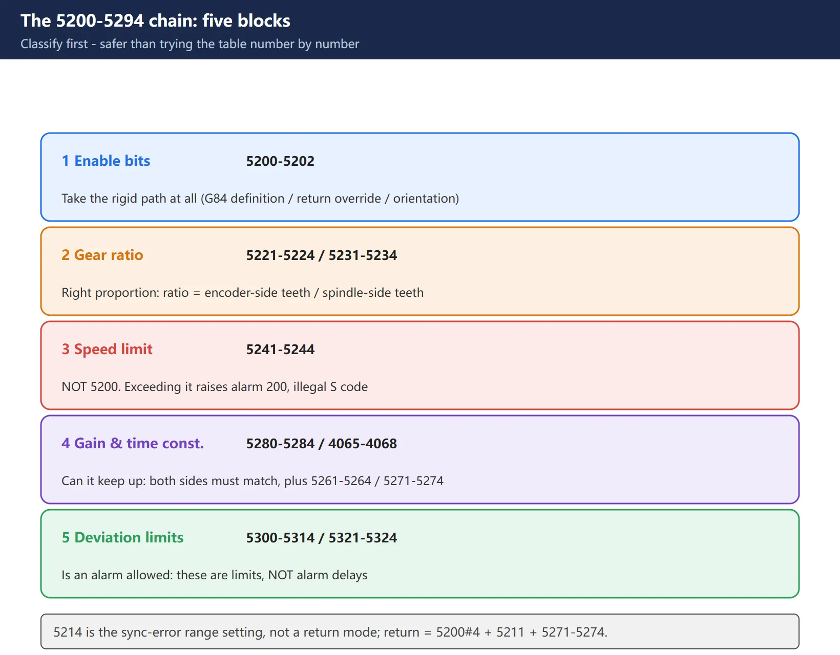
The group splits into five functional blocks. Classify before you touch anything – it beats working down a parameter table one number at a time.
2.1 Enable bits: do you take this path at all
- 5200#0 (G84):
0= G84 is ordinary (floating) tapping;1= G84 defaults to rigid tapping.
– During commissioning set 0 and call M29 explicitly; switch to 1 once production is stable.
- 5200#1 (VGR): whether an arbitrary gear ratio between spindle and position encoder is allowed in rigid tapping.
- 5200#2 (CRG): rigid tapping cancel method.
- 5200#4 (DOV): whether feed override is effective during rigid tapping return. Set
0on automated lines to lock the override. - 5200#5 (PCP): high-speed chip-clearing tapping cycle.
- 5200#6 (FHD): whether feed hold / single block is effective during rigid tapping.
- 5200#7 (SRS): spindle selection for rigid tapping in multi-spindle control.
- 5201#0 (NIZ): smoothing control during rigid tapping.
- 5201#2 (TDR): cutting-constant selection during rigid tapping.
- 5202#0 (ORI): spindle orientation on entering the tapping cycle. Enable for deep holes and frequent retract to reduce accumulated thread error.
2.2 Gear ratio: does the proportion match (wrong = permanent torn threads)
On machines where the spindle encoder is driven through a belt or gears, this block must match the mechanics:
- 5221–5224: rigid tapping spindle-side tooth count (gear 1 to 4)
- 5231–5234: rigid tapping position-encoder-side tooth count (gear 1 to 4)
- Ratio = encoder-side teeth ÷ spindle-side teeth
With a directly coupled encoder (1:1), set both sides equal. Re-check after changing a timing pulley or rebuilding the spindle – a wrong value raises no alarm, it just tears threads consistently.
2.3 Speed limit: not 5200, it is 5241–5244
⚠️ Correcting a very widely repeated error: the spindle speed limit is not 5200. It is:
- 5241–5244: rigid tapping spindle maximum speed (gear 1 to 4)
An S command above this range triggers alarm 200 (illegal S code). To change the ceiling, change 5241–5244 – 5200 has nothing to do with it.
2.4 Gains and time constants: can the axis keep up
- 5280: rigid tapping position loop gain for spindle and tapping axis (common value).
- 5281–5284: the same, per gear (active when 5280 is 0).
- 5291–5294: gain multiplier per gear.
- 4065–4068: rigid tapping spindle-side loop gain per gear – must be set equal to 5280 / 5281–5284. This is the most commonly skipped step. With mismatched spindle and axis gains, sync error will never come down.
- 5261–5264: rigid tapping entry acceleration/deceleration time constant per gear. Increase for stainless and deep holes; shorten for aluminium and shallow holes.
- 5271–5274: rigid tapping return acceleration/deceleration time constant per gear. If the retract phase misbehaves, tune here first.
- 4099: delay for stable motor excitation during rigid tapping.
2.5 Deviation limits: is an alarm allowed
- 5310: tapping axis position deviation limit during motion
- 5311: spindle position deviation limit during motion
- 5312: tapping axis deviation limit at stop
- 5313: spindle deviation limit at stop
- 5314: tapping axis movement deviation limit
- 5300 / 5301: in-position width for tapping axis / spindle
- 5321–5324: spindle backlash per gear
⚠️ Second correction: 5310/5311 are deviation limits, not alarm delays. Set too large they stop protecting you (torn threads and no alarm); set too small they trigger spurious SP0741. On worn ballscrew machines you may widen them – but pair that with backlash compensation.
Also note 5214 is the rigid tapping sync-error range setting, not a “return mode”. Return-related parameters are 5200#4 (override effective), 5211 (return override value) and 5271–5274 (return time constants). Do not mix them up.
3. M29 and G84: three calling forms
Any one of three forms works:
Form 1: M29 on the preceding block (recommended)
M03 S600;
M29 S600;          ; activate rigid tapping sync mode
G84 X_ Y_ Z_ R_ F1.5;
Form 2: same block as G84
G84 X_ Y_ Z_ R_ F1.5 M29 S600;Form 3: G84 alone as rigid tapping
Driven by 5200#0 = 1; G84 itself runs rigid tapping and M29 is not needed.
Two feed modes – the F word is written completely differently:
- Feed per revolution (G99):
Fis the pitch. M6×1.0 at S1000 →F1.0 - Feed per minute (G98):
F = S × pitch. S1000 with 1.0 pitch →F1000
⚠️ This is the single most common field error. Writing a per-minute feed under G99 is the classic cause of torn threads. Prefer G99: the program decouples from speed, and changing rpm needs no F edit.
⚠️ Third correction: there is no such thing as “per-revolution feed parameters 5201/5202”. 5201#0 is the smoothing switch and 5201#2 is cutting-constant selection; F is determined entirely by G99/G98 and the pitch.
4. Diagnostic 452 / 453: reading sync error and setting thresholds
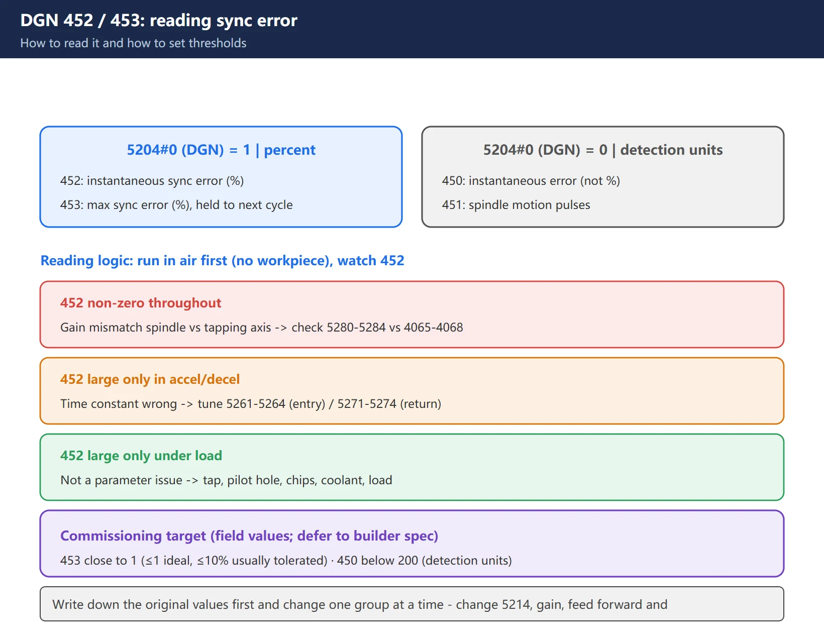
Parameter 5204#0 (DGN) selects how the diagnostic screen displays:
| 5204#0 | DGN | Meaning |
|---|---|---|
| 1 | 452 | Instantaneous sync error between spindle and tapping axis (%), positive = spindle leads |
| 1 | 453 | Maximum sync error (%), held until the next cycle |
| 0 | 450 | Instantaneous error in detection units (not %) |
| 0 | 451 | Spindle motion pulses (detection units) |
Commissioning targets (common field values; defer to the builder’s accuracy spec):
- 453 as close to 1 as possible (≤1 ideal; up to about 10% is still commonly tolerated)
- 450 below 200 (detection units)
How to read it:
- Run the program in air first and watch 452. If 452 is non-zero throughout → gain mismatch between spindle and tapping axis; check that 5280–5284 and 4065–4068 are set to the same value.
- If 452 is large only during accel/decel → time constant problem; adjust 5261–5264 (entry), 5271–5274 for the retract phase.
- If 452 is large only under cutting load and fine in air → not a parameter problem. Go to tooling, hole preparation, chip evacuation, coolant and mechanical load (section 5).
- Always re-run air + trial cut after any change and check that 453 converges.
⚠️ Write down the original values before starting, change one group at a time, and record it. Change 5214, gain, feed forward and time constants together and you can no longer tell which one did anything.
5. SP0741 alarm: failed spindle or wrong parameters?
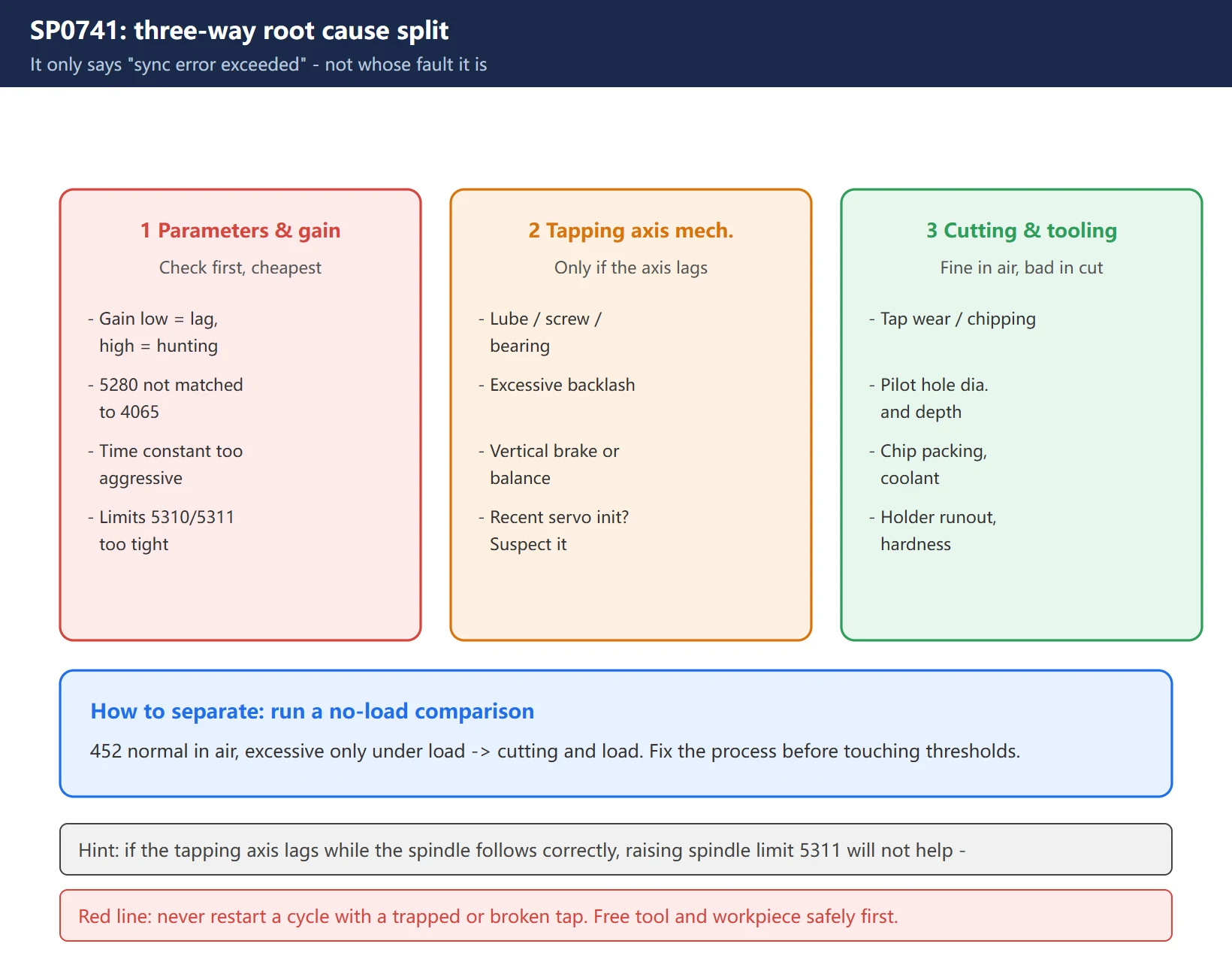
SP0741 / SV0741 = rigid tapping excess error. It only says “sync error exceeded the limit” – it does not tell you whose fault it is. Split three ways: parameter/gain side, tapping-axis mechanical side, cutting load side.
1) Parameters and gain (check first, cheapest)
- Position loop gain too low → excessive following lag; too high → overshoot, hunting, unstable reversal
- 5280 (or 5281–5284) and 4065–4068 mismatched → sync error will not come down
- Acceleration/deceleration time constant too aggressive → one side lags during accel or reversal
- Deviation limits (5310/5311) set too tight → normal variation alarms
2) Tapping axis mechanics
- Poor lubrication; worn ballscrew / bearings / guides / coupling; excessive backlash
- Vertical-axis brake or counterbalance fault
- Holder and axial compliance, servo load and torque
- Recent servo parameter initialization or motor replacement (suspect this first if init was just done)
- Diagnostic hint: if the tapping axis lags while the spindle follows correctly, raising the spindle deviation limit (5311) will not help – go to the axis side.
3) Cutting and tooling
- Tap size, geometry, coating, wear, damage
- Pilot hole diameter and usable depth, blind-hole clearance
- Poor chip evacuation, chip packing
- Cutting fluid and lubrication delivery
- Holder/collet runout, spindle taper condition
- Workpiece hardness variation
How to separate them: run a no-load program for comparison. If 452 is normal in air and only exceeds under load, the problem is cutting and load – fix the process first, then consider touching the alarm threshold.
⚠️ Red line: never repeatedly restart a cycle with a trapped or broken tap. Confirm the tool and workpiece can be separated safely before moving either axis.
6. Five field traps
- Speed above the ceiling. An S command above 5241–5244 → alarm 200 (illegal S code). The ceiling lives in 5241–5244, not 5200.
- Gear ratio 5221/5231 not matching the mechanics. Pulley changed or spindle rebuilt without updating the ratio → consistent torn threads, no alarm.
- Gains mismatched between the two sides. Only 5280 changed, 4065–4068 forgotten → sync error never comes down however you tune.
- Per-minute feed written under G99. The classic torn-thread cause, especially easy to miss after a speed change.
- M29 and G84 used inconsistently. With 5200#0 = 1 (G84 already rigid), additionally writing M29 and a different S value can create a conflict (alarms 203/204/205 class).
7. Acceptance checklist
- [ ] Air run: diagnostic 453 ≈ 1 (or ≤ 10%), 450 < 200
- [ ] Air run: 452 zero throughout (gains matched)
- [ ] Trial cut: go/no-go gauge passes on every thread
- [ ] 100 consecutive taps with no SP0741 / 200 / 203
- [ ] Repeat after every gear change (5221–5224 / 5231–5234 / 5241–5244 / 5261–5264 are per gear)
- [ ] Re-test after a speed change (no F edit needed under G99, but confirm 5241–5244 is high enough)
- [ ] Original parameters backed up, all changes recorded
FAQ
Does Fanuc rigid tapping always need M29? Can I just write G84?
It depends on parameter 5200#0 (G84):
- Set to
0→ G84 is ordinary (floating) tapping; M29 is required to enter rigid mode. - Set to
1→ G84 itself runs rigid tapping; M29 can be omitted.
M29 has three forms: M29 S__; on the preceding block then G84 ...; the same block as G84 ... M29 S__;; or relying on 5200#0=1 so G84 carries it.
One caveat: even when the parameter allows omitting M29, some machine builders still require a pre-arm M code in the ladder (commonly M29 itself). If the program still does not enter rigid mode (alarms 203/205), inspect the PMC ladder condition feeding G61#0 (rigid tapping signal). During commissioning, write M29 explicitly – it is far easier to troubleshoot than relying on an implicit parameter behaviour.
Is SP0741 a failed spindle or wrong parameters?
Do not conclude either way up front. SP0741 / SV0741 only states that the sync error between spindle and tapping axis exceeded the limit; it is a result, not a cause.
Work from cheapest to most expensive:
- Read the diagnostics first. Run in air; if 452 is non-zero throughout, it is almost certainly a gain mismatch – verify that 5280 (or 5281–5284) and 4065–4068 hold the same value. A few minutes rules this out.
- Then the time constants. If 452 is large only in accel/decel, tune 5261–5264 (entry) / 5271–5274 (return).
- Normal in air, excessive under load → not a parameter issue. Check tap wear/chipping, pilot hole size, chip evacuation, coolant, holder runout; and on the axis side lubrication, ballscrew, coupling and vertical-axis counterbalance.
If the tapping axis lags while the spindle is fine, increasing spindle deviation limit 5311 does nothing – go to the axis mechanics and servo load.
DGN 452 reads a large deviation but the thread is fine – should I care?
Investigate, but do not necessarily change anything yet. Two cases:
- Large in air (not cutting) → the spindle and tapping axis have mismatched dynamic response, usually 5280 versus 4065–4068 mismatch. The thread “happens to be fine” only because the load is light and the speed low; raise the speed or cut harder material and it will start tearing. Match the gains so 452 returns to zero in air.
- Large only under cutting load → normal reflection of cutting force. Focus on whether 453 (max error) converges to an acceptable value and re-check tooling and process. If the gauge passes and 453 is stable, it is acceptable.
Either way, 453 is the trend indicator – it holds the maximum deviation of the whole tapping cycle, which is exactly what you are trying to drive toward 1.
Last updated: 2026-10-31
Quick reference: Fanuc rigid tapping parameter chart — the on-machine lookup: the five blocks of 5200-5294, DGN 452/453/450/451 target values, the three SP0741 root causes, and alarms 200-205.
Related: Rigid tapping on an analog spindle: G61.0 sync and the three-layer SP742 check — this page explains the tapping parameter chain; that one covers the drive-side requirements and why reversed A/B phases trip SP742 immediately. Read both when tapping on a VFD spindle.
Where to go next
- FANUC Troubleshooting — the full guide library: alarms, diagnosis numbers, servo, spindle, PMC and electrical faults, organised by symptom.
- CNC Repair Tools — which instrument measures what: multimeters, clamp meters, insulation testers and oscilloscopes, with the specification that actually matters.
- Remote Technical Support — have the readings reviewed with you: alarm reverse lookup, PMC ladder analysis and servo tuning advice by call. Repair companies and integrators welcome.
Read the guide, get the right instrument, or walk the diagnosis through with someone — pick whichever you need.
The original Chinese version — same procedure, with the full field notes.












暂无评论内容