


🚨 Scope and compliance: Ranges and landmark numbers are cross-checked against the Fanuc parameter manuals (30i/31i/32i-B Plus
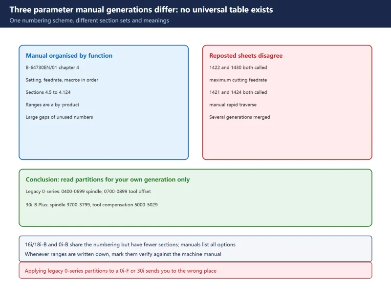
B-64730EN/01, chapter 4, sections 4.5-4.124;B-63530EN;GFZ-63840EN) and publicly available third-party parameter indexes. Manual text, bit-definition figures and per-number descriptions are copyright material; this page provides objective grouping and lookup navigation only, and offers no manual download link, file mirror, archive or bundled package. The meaning, bit definition, valid range and even the existence of any parameter on your control must be confirmed against the parameter manual supplied with that specific CNC model and software version. The widely reposted “0000-0027 system / 0400-0699 spindle / 0700-0899 tool offset” layout belongs to legacy 0-series controls and must not be applied to a 0i-F or 30i.1422versus1430, and1421versus1424, carry different meanings across generations; this page does not adjudicate them and marks them “verify against the machine-specific manual”.
30-Second Triage: What Are You Holding
Table 0 – Six field needs and where to start
1. Why No Universal Parameter Table Exists
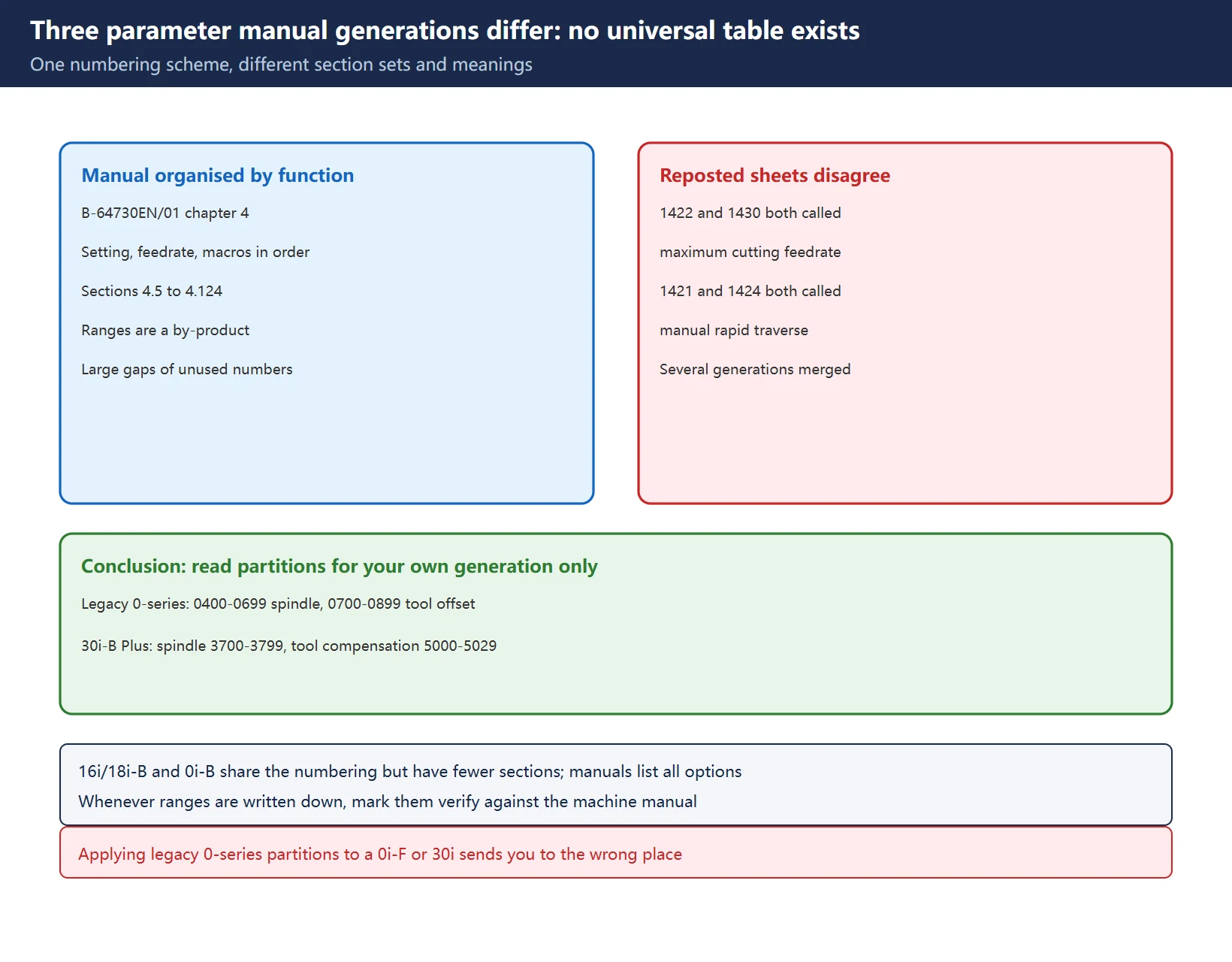
Treating “range to function” as a fixed dictionary is the classic field mistake. Three verifiable facts:
- The manual is organised by section, not by a continuous run of numbers. Chapter 4 of
B-64730EN/01starts with “Parameters of Setting” and continues through feedrate, axes, servo, display and editing, macros, tool compensation and spindle, with section numbers from 4.5 to 4.124. Ranges are a by-product of those sections, and large gaps of numbers are unused. - Same numbering scheme, different section sets. The 16i/18i-B and 0i-B manuals use the same numbers with fewer sections. Legacy 0-series controls differ more sharply: reposted Chinese tables put spindle at
0400-0699and tool offset at0700-0899, while the 30i-B Plus manual places spindle control at3700-3799and tool compensation at5000-5029. - Reposted tables contradict themselves. One widely copied “common Fanuc parameters” list defines
1422as maximum cutting feedrate and then defines1430as maximum cutting feedrate per axis in the same table;1421and1424are both described as manual rapid traverse. That is not a typo – parts of several manual generations were merged into one sheet.
| Dimension | 30i/31i/32i-B Plus (B-64730EN/01) | 16i/18i-B / 0i-B | Legacy 0-series (third-party layout) |
|---|---|---|---|
| Organising principle | Chapter 4 functional sections, 4.5-4.124 | Same scheme, fewer sections | Number bands grouped by function, third-party source |
| Spindle block | 3700-3799 | Broadly inherited, check the supplied manual | 0400-0699 and 3000-3299 both appear |
| Tool compensation block | 5000-5029 | Broadly inherited | 0700-0899 and 4000-4999 both appear |
| Feedrate block | 1401-1465 (1420 rapid) | Inherited, bit definitions may differ | 1400-1600, with duplicated 1422/1430 descriptions |
| PMC block | 11900+ multi-PMC execution order | Older i-series clusters near 9000 | 9000-9999 PMC signals and K-address mapping |
| Interchangeable? | No | No | No |
Table 1 – How the three manual generations differ (framework layer only, no per-number definitions)
Table 1 exists to show that a universal table cannot work, not to let you reverse-engineer a specific number. Always return to the manual supplied with the machine.
2. How Chapter 4 Is Organised: Functional Blocks
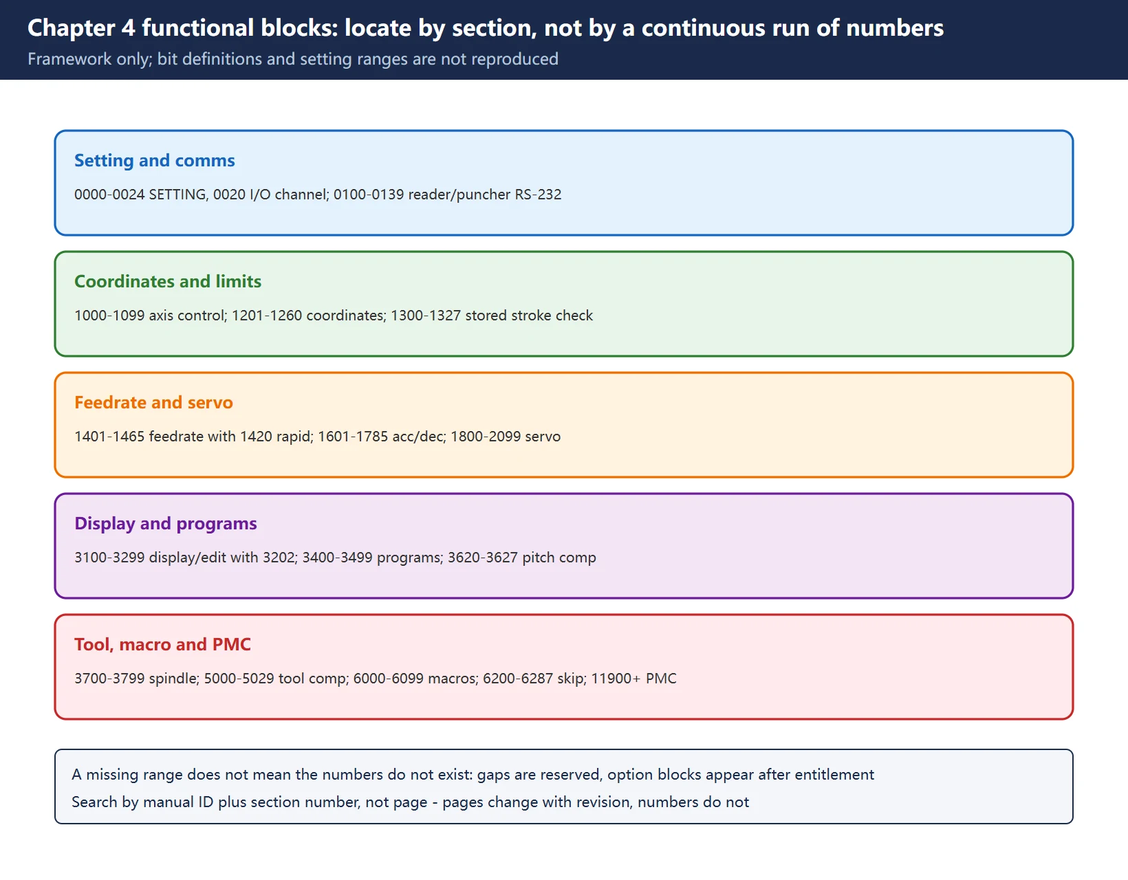
The table below follows the section order of B-64730EN/01 chapter 4 and gives only three things: range, function family, and where to look in the manual. Bit definitions, setting ranges and units are not reproduced.
| Range (decimal) | Function family | Manual landing point | Field note |
|---|---|---|---|
0000-0024 | Setting (SETTING screen) | Early chapter 4 | 0020 selects the I/O channel for program transfer |
0100-0139 | Reader/puncher (RS-232) interface | Communication section | One group per channel; record originals |
1000-1099 | Axis control / increment system | Axis and coordinate sections | 1001 mm/inch, 1002 JOG behaviour |
1201-1260 | Coordinates | Coordinate section | 1240 reference position in machine coordinates |
1300-1327 | Stored stroke check (soft limits) | Stroke check section | Directly tied to overtravel alarms |
1401-1465 | Feedrate | Feedrate section | 1420 rapid traverse per axis; verify 1422/1430 locally |
1601-1785 | Acceleration/deceleration | Acc/dec section | 1622 cutting feed accel/decel time constant |
1800-2099 | Servo | Servo section | 1825 servo loop gain, 1851 backlash compensation |
3001-3033 | DI/DO machine interface signals | Interface signals section | Related to the PMC signal chain |
3100-3299 | Display and edit | Display/edit section | 3202/3204 program protection, 3210/3211 password |
3400-3499 | Programs | Program section | 3401 editing behaviour, 3457 folder search order |
3620-3627 | Pitch error compensation | Dedicated section | Entered on the pitch compensation screen, not the general parameter screen |
3700-3799 | Spindle control | Spindle section | 3741 maximum spindle speed for gear 1 |
5000-5029 | Tool compensation | Tool compensation section | 5001 tool length compensation type bits |
5101-5199 | Canned cycles | Canned cycle section | 5101 drilling cycle bits |
5200-5321 | Rigid tapping | Rigid tapping section | 5200 G84-related bits |
6000-6099 | Custom macros | Macro section | 6050-6059 G-code calls, 6071-6089 M-code calls |
6200-6287 | Skip function (G31, probing) | Skip section | 6200/6201 skip signal bits |
6300-6399 | External data input/output | External I/O section | Related to program number search |
6700-6758 | Run hour and parts count | Counter section | 6710 parts-count M code |
8130s | Basic function selection | Function selection section | Power-off activation class |
11900+ | Multi-PMC execution order | PMC section | Power-off activation class |
Table 2 – Chapter 4 range-to-function framework in section order (not a per-number table)
A range missing from the table does not mean the number does not exist. Large gaps are reserved between sections, and option-specific blocks (expanded macro variables, AI contour control levels, additional axes) appear only when the corresponding option is authorised. That is exactly the hiding mechanism covered in Why parameters disappear.
3. Verifiable Landmark Parameters
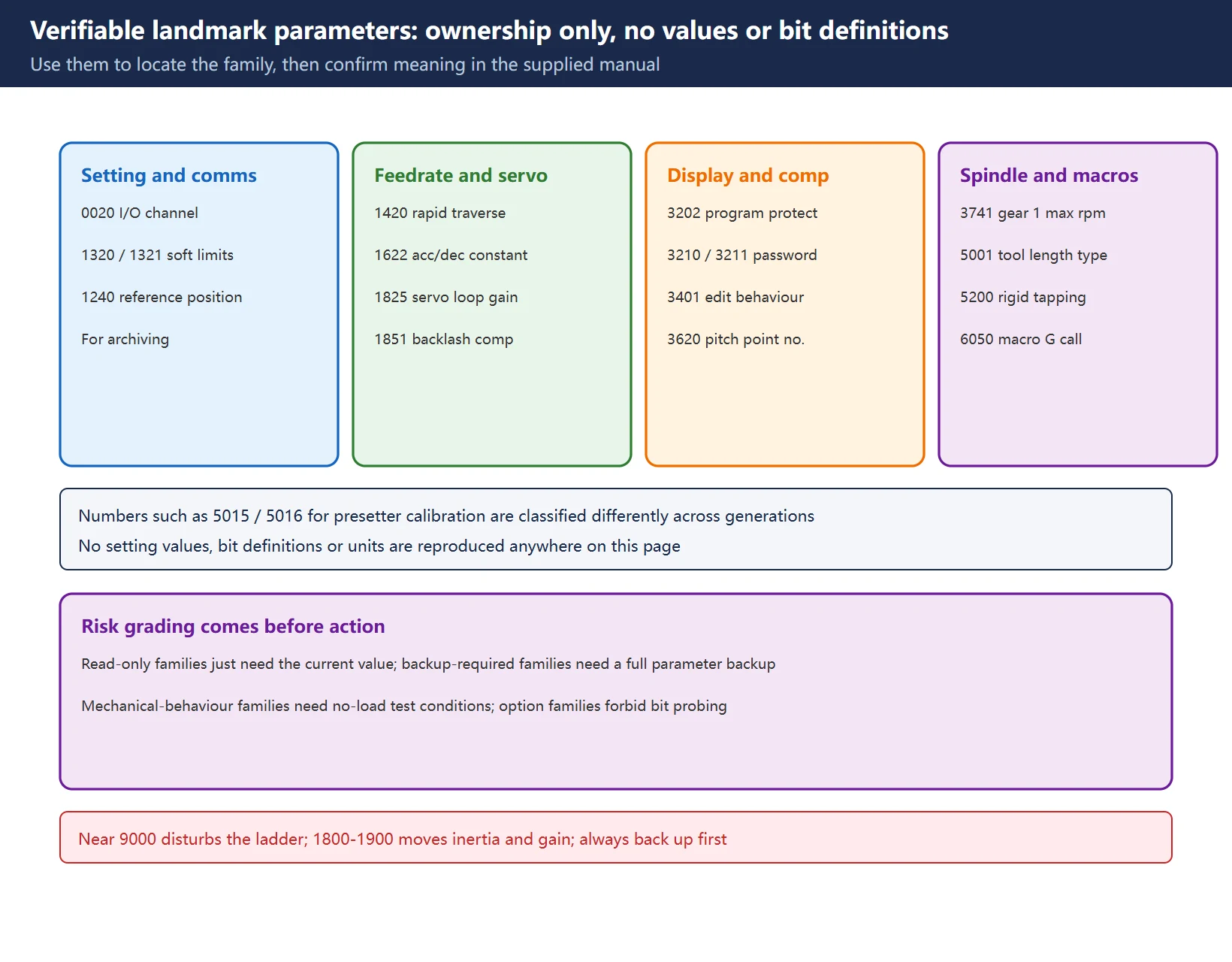
Only numbers whose ownership can be traced to the official parameter manual are listed. They are anchors for “find the family from the number”. No setting values, bit definitions or units are given here.
Table 3 – Verifiable landmark parameters and their families (ownership only, no bit definitions or values)
🔎 Numbers such as
5015/5016, associated with tool presetter calibration in some generations, are not consistently classified across manuals. They are kept here at anchor level only; confirm meaning against the machine-specific manual.
4. Change-Risk Grading
| Risk class | Typical families | Before changing | After changing |
|---|---|---|---|
| Read-only observation | Display, counters, run hours, diagnostics | Record the current value | Watch the screen reading |
| Backup required | Setting, program protection, communication, I/O channel | Full parameter backup plus original values | Retest transfer and protection |
| Affects mechanical behaviour | Servo gain, acc/dec, pitch compensation, backlash, soft limits | Backup plus no-load test conditions | Low-speed no-load run, bidirectional positioning, circularity or test cut |
| Option entitlement related | Macro variable range, additional axes, advanced contour, option bits | Confirm the entitlement record; do not probe by flipping bits | Confirm through the builder or an authorised channel |
| Power-off activation class | Some axis configuration, function selection, multi-PMC order | Backup plus a planned downtime window | Power-cycle and verify item by item |
Table 4 – Change-risk grading by function family (not a per-number list)
Before touching anything, work through Data backup and recovery, Export and print parameter tables and Parameter write protect (PWE), and remember to restore PWE to 0 afterwards. Changing PMC-related parameters near 9000 can disturb the ladder; changing the 1800-1900 servo block moves inertia and gain behaviour. Never experiment on a machine without a backup.
5. What We Refuse to Invent
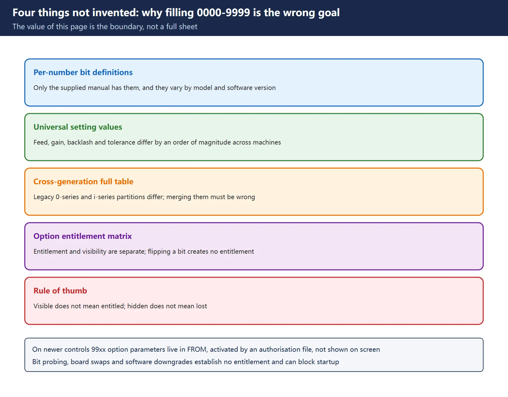
This is the most important boundary on the page. Many “complete Fanuc parameter lists” manufacture authority by filling every number from 0000 to 9999, which in practice means stitching together three manual generations. Four categories are deliberately absent:
| Not invented | Why | What to do instead |
|---|---|---|
| Per-number bit definitions and setting ranges | Only the supplied manual has them, and they vary by CNC model and software version | Search by manual ID plus section number |
| Universal setting values (feed, gain, backlash, tolerance) | Machine classes and accuracy grades differ by an order of magnitude | Use the builder specification and supplied manual |
| A cross-generation “0000-9999 full table” | Legacy 0-series and i-series partitions differ; merging them must be wrong | Read the framework for your own generation only |
| An option entitlement matrix (which bit turns on which function) | On newer controls entitlement and visibility are separate; flipping a bit is not an entitlement | Check the option record and contact the builder or Fanuc |
Table 5 – Four categories we do not invent and the alternative for each
The last row matters most: on newer controls, option parameters in the 99xx region are not displayed on the parameter screen at all. They live in FROM and are activated by an authorisation file. Repeatedly changing bits, swapping boards or downgrading system software establishes no valid entitlement and may leave the control unable to boot. That is not “a hidden parameter” – entitlement and visibility are simply two different things.
6. Official Manual Lookup Keys
| Key | Content | How to use |
|---|---|---|
B-64730EN/01 | 30i/31i/32i-B Plus parameter manual | Chapter 4 by function, sections 4.5-4.124 |
B-63530EN | 16i/18i-B parameter manual | Same numbering scheme, fewer sections |
GFZ-63840EN | 0i-B parameter manual | Legacy i-series reference |
| Manual type + software version + section number | General practice | Search by number, not page – pages change with revision, numbers do not |
| Control model and series name | SYSTEM / software version screen | Identify the generation before choosing a manual |
| Builder specification and contract | Options and configuration | Decide which functions were actually purchased |
Table 6 – Six official lookup keys
7. Internal Parameter Index
Table 7 – Internal parameter-level index (published pages, linked back by family)
Frequently Asked Questions
What do Fanuc parameters 8000 through 9999 control?
There is no cross-model answer. In the 30i/31i/32i-B Plus manual, the 8000 region covers basic function selection and PMC-related content has moved to 11900+. In third-party layouts for legacy 0-series controls, 8000-8399 is grouped as basic fourth-axis servo parameters and 9000-9999 as PMC signals and K-address mapping. Those are different generations, and merging them sends you to the wrong place. Identify the control model and software version on the SYSTEM screen first, then search the matching manual by number.
Which range is servo, and which is tool compensation?
Under the B-64730EN/01 framework, 1800-2099 is servo (1825 position loop gain and 1851 backlash compensation live there), 5000-5029 is tool compensation (5001 tool length compensation type), canned cycles are 5101-5199 and rigid tapping is 5200-5321. That is the 30i/31i/32i-B Plus layout; 0i-B and 16i/18i-B have different section counts and some ownership differs, and legacy 0-series differs more. Use Table 2 to locate the family, then confirm the exact number in the supplied manual.
Under what conditions does a whole parameter range disappear?
At least four distinct mechanisms: an unauthorised option, axis-count filtering, model and software version differences, and newer controls moving option parameters off the parameter screen into FROM. Note that not displayed does not mean lost – in most cases the data is still in non-volatile memory and only the listing is filtered. More importantly, visible does not mean entitled: on newer controls, flipping bits repeatedly, swapping boards or downgrading software cannot create an entitlement and can prevent the control from booting. A step-by-step field check is in Why parameters disappear.
Last updated: 2026-11-15
Beyond the range framework: where 5015-5018 sit in the offset block
Beyond the range framework: 1420-1425 belong to the feed-rate group
Beyond the range framework: comparing model ceilings and options
Beyond the range framework: options govern real capability
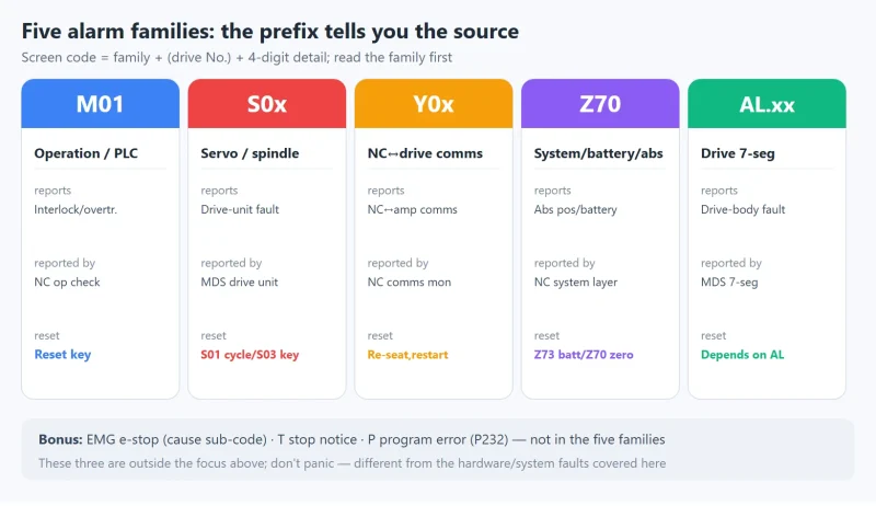
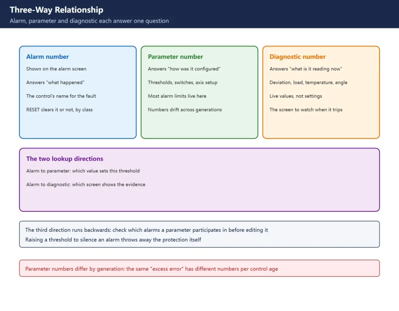
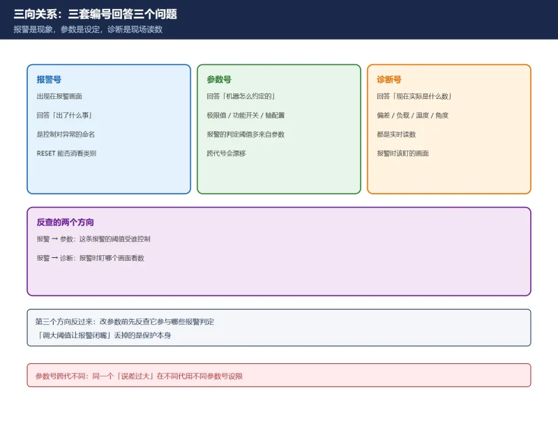
Beyond parameter bands: mapping parameters back to alarms
Where to go next
- FANUC Troubleshooting — the full guide library: alarms, diagnosis numbers, servo, spindle, PMC and electrical faults, organised by symptom.
- CNC Repair Tools — which instrument measures what: multimeters, clamp meters, insulation testers and oscilloscopes, with the specification that actually matters.
- Remote Technical Support — have the readings reviewed with you: alarm reverse lookup, PMC ladder analysis and servo tuning advice by call. Repair companies and integrators welcome.
Read the guide, get the right instrument, or walk the diagnosis through with someone — pick whichever you need.
The original Chinese version — same procedure, with the full field notes.























暂无评论内容