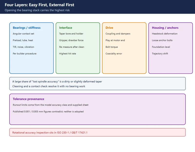



🚨 Scope and compliance: The four-layer split, the two-point test-arbor method, the high-spot phase test, taper contact-pattern checking with layout blue, drawbar force verification, and the distinction between constant-pressure and fixed preload on this page come from public spindle service and machining references (industrialmonitordirect, glcncmachining, anebon and similar) plus field-maintenance compilations. All are third-party sources; no single builder’s official spindle service manual was verified clause by clause here. They are diagnostic reasoning, not a work instruction. The numerical values those sources publish (radial runout limits such as 0.01 / 0.005 mm, taper contact 80% or 85-90%, CAT40 / BT40 drawbar force of 1200-1500 kgf, test-arbor distances of 20/25/100/150/200/300 mm from the nose, lapping passes, oil-bath temperatures, warm-up durations and tool overhang ratios) conflict with each other and depend on the machine model; this page adopts none of them as a universal limit and states instead “per the machine’s accuracy class, builder torque values and supplied acceptance sheet”. No numerical tolerance table is reproduced. Lapping a spindle taper changes the taper and axial position and is a specialist-builder repair process, explicitly not presented here as a do-it-yourself field procedure. Manuals and standards are copyright-protected; no downloads, cloud-drive links or bundled files are offered. Spindle disassembly involves stored spring energy, heavy lifting, live conductors and high-speed rotating parts; only qualified personnel following the builder’s written procedure and lockout/tagout rules should perform it.
30-Second Triage: Locate the Layer Before Ordering Bearings
| Observation | More likely layer | First action | What not to do first |
|---|---|---|---|
| Near-point reading good, far-point reading clearly larger | Interface / arbor seating / support stiffness (two competing readings, see section 2) | Two-point test-arbor reading plus a high-spot phase test | Do not conclude “bearing preload is low” |
| Runout acceptable but parts drift or the tool wobbles | Toolholder / drawbar mechanism | Verify drawbar force; clean and inspect the taper and holder taper | Do not adjust bearing preload |
| High spot stays at the same clock angle | Bent arbor, face tilt or shaft eccentricity | Swap the test arbor / recheck seating | Do not strip the spindle for bearings |
| Cold machine passes, drifts after running | Thermal state, lubrication, temperature control | Re-measure after warm-up per procedure; record cold and warm separately | Do not judge a warm fault from a cold reading |
| Low-speed vibration, noise, abnormal temperature rise | Bearings / lubrication / preload / balance | Check lubrication, temperature rise and vibration | Do not decide from one runout reading alone |
Table 0 – Five observations and their layers
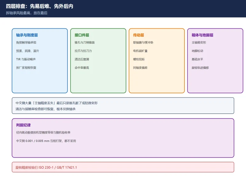
Spindle runout belongs to the rotational accuracy error family, whose inspection method sits in ISO 230-1 / GB/T 17421.1 (no-load or quasi-static conditions); VDI/DGQ, JIS and ASME are separate systems. Parameter compensation and servo tuning are a different layer entirely – see Machine Geometric Accuracy Check and Adjustment Framework for the framework and Fanuc Backlash Compensation 1851 for the compensation layer.
1. Four-Layer Diagnostic Framework
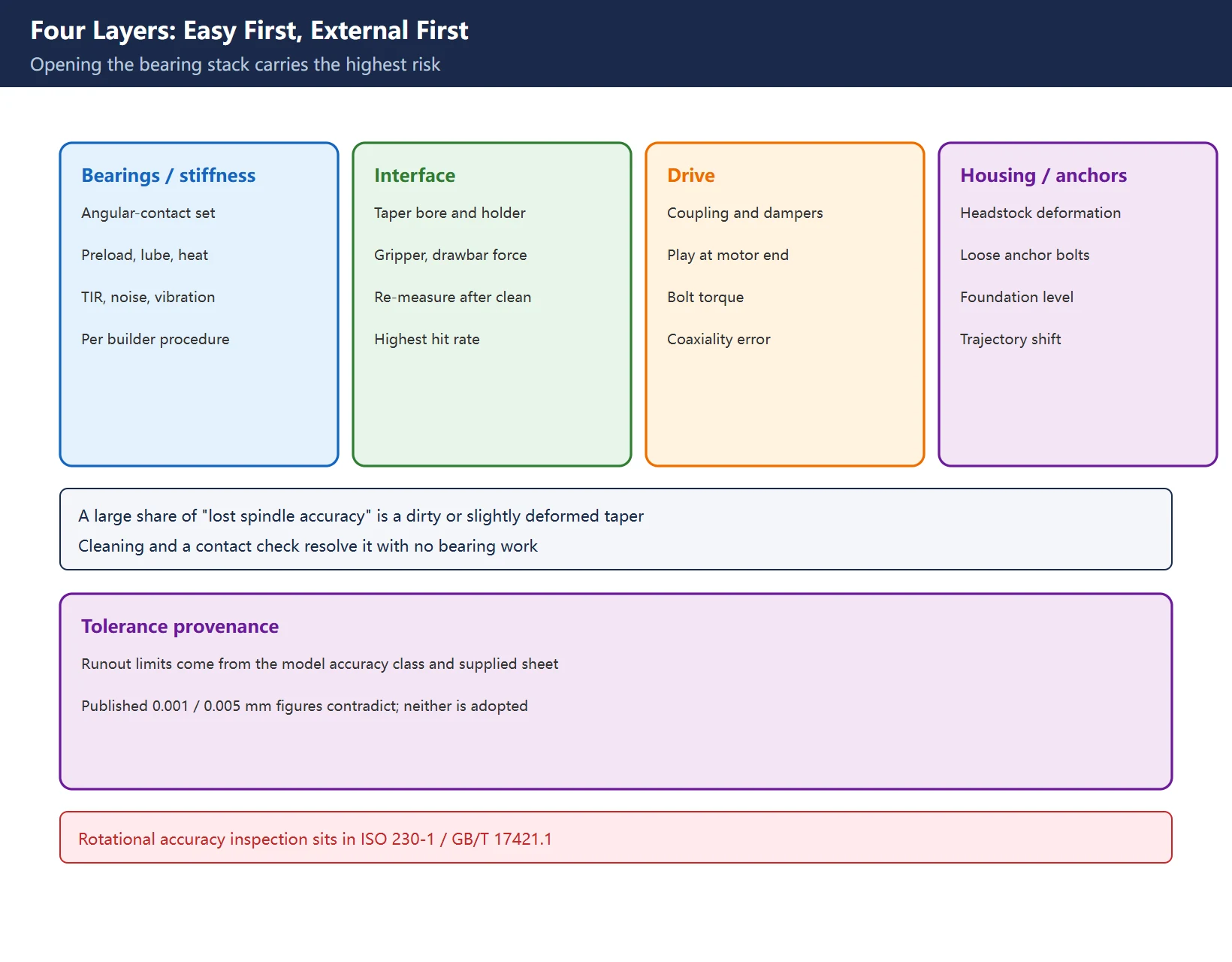
| Layer | Objects | Typical checks | Direction of action |
|---|---|---|---|
| 1 Bearing and stiffness | Angular-contact bearing set, preload, lubrication, temperature rise, balance | TIR, temperature rise, vibration and noise, lubrication supply | Restore preload per builder procedure or refer for a professional rebuild |
| 2 Interface | Taper bore, toolholder / arbor taper, gripper and drawbar force, face contact | Re-measure after cleaning, contact pattern, drawbar force test | Clean, repair or replace interface parts |
| 3 Drive | Coupling, dampers, play at the motor end, bolt torque | Turn the motor end by hand to feel play; check coaxiality | Reassemble to builder torque and coaxiality requirements |
| 4 Housing and foundation | Headstock deformation, loose anchors, foundation level | Recheck anchors and level; observe the rotation trajectory | Re-torque and re-level per assembly procedure |
Table 1 – Four-layer diagnostic framework
The order is “easy first, external first”: the interface layer needs only cleaning and a test indicator and gives the highest return; the bearing layer carries the highest disassembly risk and cost, so it comes last. For the electrical and pneumatic side of the clamping mechanism, see Spindle Unclamp Failure / Tool Not Seated; this page covers mechanical accuracy only.
2. The Two-Point Split: Two Readings That Must Be Kept Side by Side
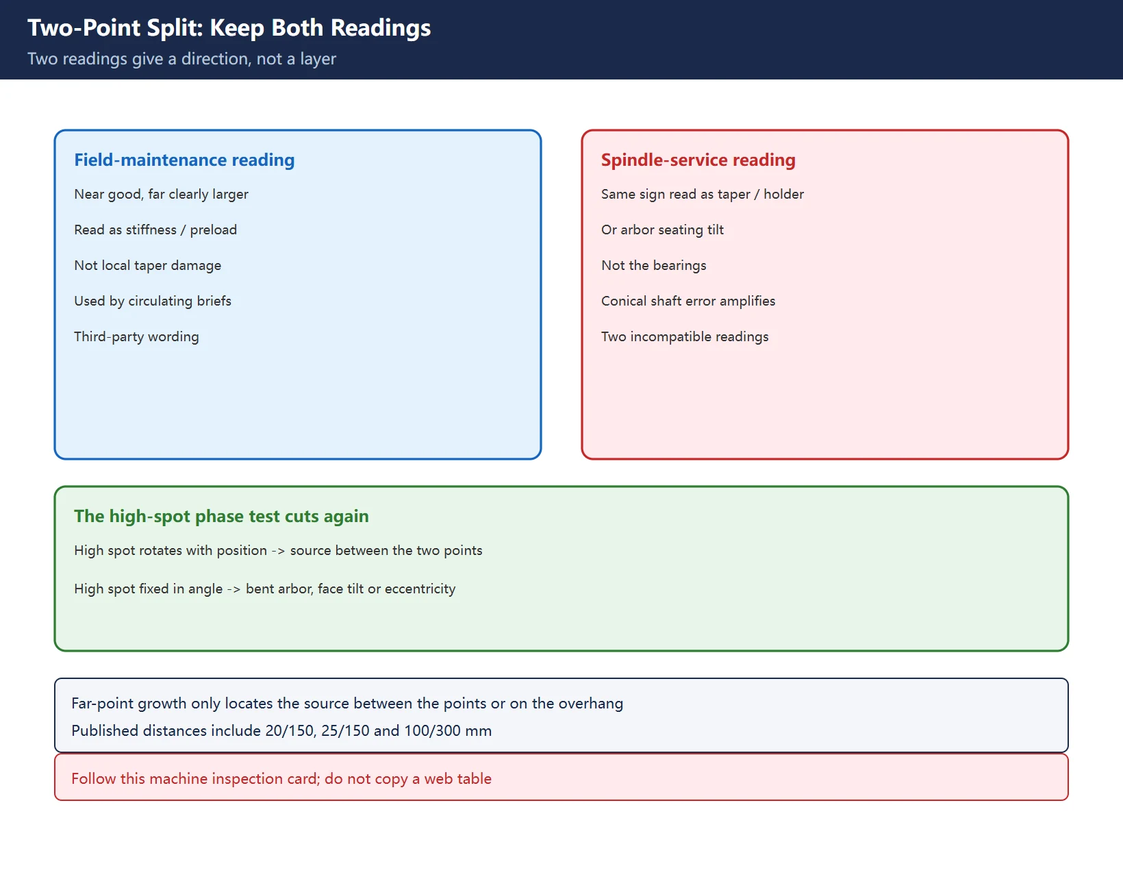
The method itself transfers across languages: seat a certified test arbor in the spindle taper at the specified drawbar force, read TIR with a test indicator at a position near the nose and a position further out, rotating the spindle slowly by hand through a full revolution, then compare both the two readings and the angular position of the high spot. Published measuring distances vary widely (20 / 150-200 mm, 25 mm / 150 mm, 100 / 300 mm, 30 / 180 mm and others), so follow this machine’s inspection card; no single pair is adopted here.
The disagreement is in the interpretation:
| Source reading | Interpretation of “near good, far clearly larger” | How this page handles it |
|---|---|---|
| Chinese-language field-maintenance compilations | Insufficient support stiffness or bearing preload, not local taper damage | Recorded as one reading |
| English-language spindle service / machining references | Usually the taper or toolholder interface, not the bearings; far-point amplification can also come from arbor seating tilt or a conical shaft error | Recorded as the other reading |
| High-spot phase test (third-party service cases) | High spot rotates as the measuring point moves out -> error source lies between the two points; high spot fixed at one clock angle -> bent arbor, face tilt or eccentricity | Recommended as the actionable next step |
Table 2 – Two conflicting interpretations of the two-point result and the way to subdivide
The conclusion: two readings give a direction, not a layer. Far-point amplification means the error source lies between the two measuring points or beyond the near point on the overhang – it may be the interface, arbor seating, support stiffness, or a bearing inner race not fully seated on its journal. The high-spot phase test cuts once more before deciding whether to clean the interface or open the bearing stack. Promoting either interpretation to a single verdict is exactly how copied guides become progressively more absolute than the evidence.
3. Taper Contact Pattern Checking: The Highest-Return Check
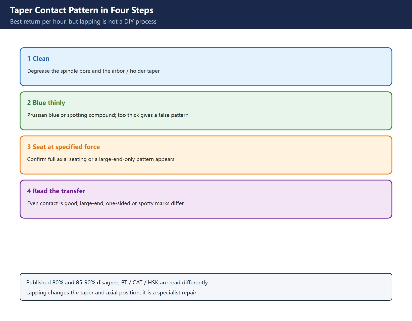
| Step | What to do | Reading direction |
|---|---|---|
| 1 Clean | Degrease the spindle taper bore and the arbor / holder taper with solvent | Chips, coolant film and rust are the most common sources of false runout |
| 2 Blue | Apply a thin, even film of layout compound (Prussian blue / spotting blue / red lead paste) to the taper | Too thick a film produces a false contact pattern |
| 3 Seat | Clamp at the specified drawbar force and confirm full axial seating | Incomplete seating produces a false “large-end only” pattern |
| 4 Read | Inspect the transferred contact pattern on the taper | Even continuous contact is desirable; large-end-only, one-sided heavy contact, and spotty / irregular marks each point elsewhere |
Table 3 – Four steps of contact-pattern checking and how to read them
Published contact percentages (80%, 85-90% and similar) disagree, and BT / CAT / HSK dual-contact tapers are read differently, so this page gives no universal percentage: judge by the interface type and the builder’s acceptance standard. Equally important: lapping a spindle taper changes the taper and the axial position and is a specialist repair process, not a do-it-yourself field operation. Field case results such as “runout reduced from 0.02 to 0.005 mm after a few lapping passes” are individual outcomes, not a transferable process or a guarantee. A large share of “lost spindle accuracy” needs only cleaning and correct re-clamping.
4. Drawbar Force and the Remaining Layers
| Check | Method family | Boundary |
|---|---|---|
| Drawbar force | Verify with a drawbar force tester against the taper specification and builder value | Acceptable runout but weak drawbar force points to the clamping mechanism, not the bearings; published kgf figures are model-specific |
| Bearing preload | Distinguish constant-pressure (spring stack) from fixed (spacer / ground offset) preload; restore to builder torque values | Not “as tight as possible”; excessive preload shows as abnormal temperature rise, judged per builder procedure |
| Bearing replacement | Replace angular-contact bearings as matched pairs, press in per procedure, never hammer | Heating method and temperature belong to the builder's service manual |
| Toolholder and clamping | Clean taper and holder taper before clamping; prefer better-repeatability holding; control overhang | Overhang ratio and runout target follow the process tolerance and tool data |
| Coupling layer | Bolt torque, damper ageing, play when turning the motor end by hand, coaxiality | Coaxiality error feeds vibration into the spindle |
| Housing and foundation | Headstock deformation, loose anchor bolts, foundation level | Check this when the whole rotation trajectory shifts |
Table 4 – Six checks and their boundaries
That fixed preload is stiffer but runs hotter while spring preload tolerates thermal growth better is a useful mechanism-level intuition, not a setting. Which arrangement a given spindle uses, and at what torque, must come from the builder’s service manual. Likewise “a clear warm-up rise above ambient after 30 minutes at no load means preload is too high” is only a screening clue – temperature rise also depends on lubrication type, speed and cooling.
5. Tolerance Provenance and Verification
| Not to be copied | Why | Correct wording |
|---|---|---|
| Radial runout limits such as 0.001 / 0.005 mm | Accuracy classes, taper sizes, measuring positions and cold / warm states differ by an order of magnitude; published figures contradict each other | Per the machine's accuracy class and supplied acceptance sheet |
| Taper contact percentages | BT / CAT / HSK are read differently; third-party 80% vs 85-90% disagree | Per interface type and builder acceptance standard |
| Drawbar force kgf tables | Taper specification and builder design differ | Verify against the taper specification and builder value |
| Measuring distances, lapping passes, heating temperatures, warm-up durations | All from single third-party cases | Per this machine's inspection card and the builder service procedure |
Table 5 – Four classes of numbers not to copy, and the wording to use instead
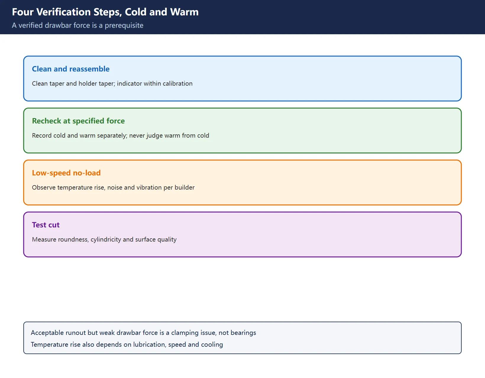
The verification loop matches the geometric-accuracy framework: clean and reassemble, recheck at the specified drawbar force and torque (recording cold and warm states separately), observe temperature rise, noise and vibration at low speed per the builder procedure, then cut the agreed test piece and measure roundness, cylindricity and surface quality. A published case where roundness degraded markedly and was traced to insufficient taper contact, resolved without changing bearings, is useful as an illustration of “check the interface layer first” – and nothing more.
6. Site Index
Table 6 – Eight further reading links
Frequently Asked Questions
How much spindle radial runout is abnormal, and where does the limit come from?
There is no cross-machine universal number. Guides that state “<= 0.001 mm" and "precision class <= 0.005 mm" contradict each other because they do not separate accuracy class, taper specification, measuring position (at the nose or at a stated distance from it) and cold versus warm state. The correct sequence is to fix the test method from the rotational-accuracy item in ISO 230-1 / GB/T 17421.1, then take the limit from the supplied acceptance sheet, the builder’s product inspection standard or the spindle data sheet for that model, recording measuring position and state. Micrometre figures in third-party articles indicate an order of magnitude, not an acceptance limit. Prerequisites for any reading are a clean taper and arbor taper, a verified drawbar force and an in-calibration indicator.
Does high spindle runout always mean new bearings, or can lapping the taper fix it?
Not necessarily – and the order is the reverse. In the four-layer framework the interface layer (cleaning, taper contact pattern, drawbar force) is cheapest and most often decisive, followed by the coupling and foundation layers; the bearing layer carries the highest disassembly risk and comes last. In a published case, markedly degraded roundness was traced to insufficient taper contact and resolved with interface and drawbar work, with no bearing replacement. But note: lapping a spindle taper changes the taper and axial position and is a specialist-builder repair process, not a do-it-yourself field operation; single-case results like “a few lapping passes reduced runout from 0.02 to 0.005 mm” are neither a transferable process nor a guarantee. Read the layout-blue contact pattern first, then decide between cleaning, replacing interface parts and referring the spindle for professional repair.
How do I use a test arbor to separate a bearing problem from a taper problem?
Use two steps: the two-point reading and the high-spot phase test. First, seat a certified arbor at the specified drawbar force and read TIR near the nose and further out, rotating slowly by hand through a full turn. A far reading markedly larger than the near one points between the two points or beyond the near point on the overhang – and here the published interpretations disagree: Chinese-language field compilations tend to write “support stiffness / preload”, while English-language spindle service references tend to write “usually the taper or toolholder interface”; arbor seating tilt produces the same signature. Two readings therefore cannot fix the layer. Second, without moving the indicator stand, move the measuring point outward along the arbor and watch whether the high-spot clock angle changes: a rotating high spot indicates the source lies between the two points (interface / bearings / conical error), while a high spot fixed at one angle suggests a bent arbor, face tilt or shaft eccentricity. Combine that with the taper contact pattern and a drawbar force test before converging on the interface layer or the bearing layer. Measuring distances follow the machine’s inspection card, not a web table.
Last updated: 2026-11-15
Where to go next
- FANUC Troubleshooting — the full guide library: alarms, diagnosis numbers, servo, spindle, PMC and electrical faults, organised by symptom.
- CNC Repair Tools — which instrument measures what: multimeters, clamp meters, insulation testers and oscilloscopes, with the specification that actually matters.
- Remote Technical Support — have the readings reviewed with you: alarm reverse lookup, PMC ladder analysis and servo tuning advice by call. Repair companies and integrators welcome.
Read the guide, get the right instrument, or walk the diagnosis through with someone — pick whichever you need.
The original Chinese version — same procedure, with the full field notes.

























暂无评论内容