


Backlash compensation (1851) only removes the lag at the instant of a direction reversal. It does nothing for position error that grows along the stroke — screw pitch error and accumulated travel error belong to pitch error compensation. On FANUC i-series controls that means parameters 3620–3624, but the biggest trap in most web guides is parameter mix-ups across generations: 0712 on a 0M and 3624 on a 0i are not the same thing, and bidirectional compensation on 16i/18i adds 3626/3627 on top.
This page walks the whole procedure — laser measurement → compensation point numbering → parameter entry → accuracy verification — with a cross-generation table so you can match the manual before touching anything. Every parameter number below was checked against FANUC parameter manuals and the Connection Manual (Function).
Start here if you have not read it yet: Fanuc Backlash Compensation 1851 — the two compensations treat different faults, and the order matters (see the FAQ).
1. When pitch compensation is mandatory: the errors backlash cannot save
Learn to tell the three faults apart before touching a parameter:
Table 1 Three types of position error and their correct fix
| Error signature | Behaviour | Correct fix |
|---|---|---|
| Reversal lag | Accurate in one direction, wrong on the return; only at direction reversal | Backlash compensation 1851/1852 |
| Accumulated travel error | Accurate near the reference point, drifting further away; error grows or oscillates with position | Pitch error compensation (this page) |
| Poor repeatability | The same point lands differently every cycle | Screw accuracy / assembly — electrical compensation cannot fix it |
One-line test: does the error change with position? Position-dependent error is pitch compensation’s job; direction-dependent, position-independent error is backlash compensation’s job.
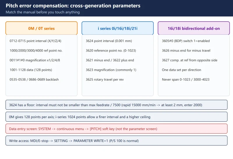
2. Cross-generation parameter table: match the manual first (the core value of this page)
FANUC pitch compensation parameters changed structure completely across generations. Using a 0i manual on a 0M — or a 0M number on a 0i — guarantees a wrong setup:
Table 2 FANUC pitch error compensation: cross-generation parameter table
| Item | 0M/0T series | i series (0i/16i/18i/21i etc.) | 16i/18i bidirectional add-on |
|---|---|---|---|
| Compensation point interval | 0712/0713/0714/0715 (X/Y/Z/4th, unit 0.001 mm) | 3624 (per axis, unit 0.001 mm) | Same 3624 |
| Reference point compensation number | 1000 / 2000 / 3000 / 4000 (X/Y/Z/4th, 0–127) | 3620 (per axis, 0–1023) | Same 3620 |
| Most distant point on the − side | Sequential downward from 1001 | 3621 | 3621 (− end for + travel) |
| Most distant point on the + side | Sequential upward to 1128 | 3622 | 3622 (+ end for + travel) |
| Magnification | 0011#1/#0 (×1/×2/×4/×8) | 3623 (commonly 1) | Same 3623 |
| Compensation data area | 1001–1128 (X) / 2001–2128 (Y) / 3001–3128 (Z) | Compensation points (0–1023 or 3000–4023 block) | Two data sets, one per direction |
| Backlash (for reference) | 0535–0538 feed / 0686–0689 rapid | 1851 / 1852 | Same as i series |
| Bidirectional switch | Not supported | — | 3605#0 (BDP) |
| Bidirectional extras | — | — | 3626 (− end for − travel), 3627 (compensation when reaching reference from the opposite side) |
Three details people miss:
- i-series point numbers come in two blocks: 0–1023 and 3000–4023 (0i-F: 0–1535 / 3000–4535), and one axis’s data must not span both blocks.
- 0M gives you only 128 points per axis (0–127), so long strokes force a coarse interval; i-series 1024 points allow a much finer interval and a higher accuracy ceiling.
- 3624 has a floor: the interval must not be smaller than maximum feedrate ÷ 7500. For an axis rapid at 15000 mm/min the interval is at least 2 mm (enter 2000), otherwise the compensation output cannot keep up.
3. Four preparations before compensation
Table 3 Four preparations before compensation (order matters)
4. Measurement and compensation point numbering
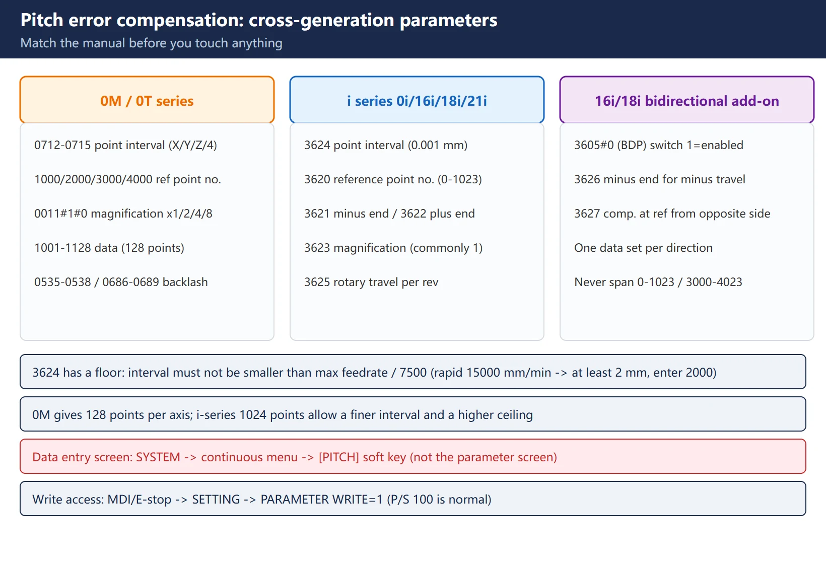
Measure with a laser interferometer, points evenly spaced along the stroke. Program structure per FANUC’s recommended test program: approach every point from one direction only (move +5 mm, then come back −5 mm to take up backlash) → G04 dwell 5 s for the laser to count → record → 5 cycles per point, averaged.
Numbering is where most mistakes happen. Worked example: X axis travel −400 to +800 mm, interval 50 mm, reference point compensation number 100:
Table 4 Point numbering worked example (interval 50 mm, reference number 100)
| Parameter | Formula | Substitution | Result |
|---|---|---|---|
| 3620 reference point number | Free choice in 0–1023, leave room both sides | — | 100 |
| 3621 most distant − point | Reference − (−travel ÷ interval) + 1 | 100 − 400 ÷ 50 + 1 | 93 |
| 3622 most distant + point | Reference + (+travel ÷ interval) | 100 + 800 ÷ 50 | 116 |
| 3624 interval | Free, ≥ max feedrate ÷ 7500 | 50 mm | 50000 (0.001 mm units) |
| 3623 magnification | Commonly 1 | — | 1 |
| Number of points | 8 on − side + 16 on + side + reference | 400/50=8, 800/50=16 | 25 points (Nos. 93–116) |
Why 3621 subtracts then adds 1: compensation points are the cells of the interval grid. Counting 8 intervals toward − from No. 100 lands on No. 92, but the farthest point itself must occupy a compensation number, hence +1 = 93. The + side needs no such correction (100 + 16 = 116).
Swapping 3621 and 3622 mirrors the compensated range: instead of being cancelled, the error is doubled — with no alarm, discovered only at laser re-verification. One of the most expensive rookie mistakes in the field.
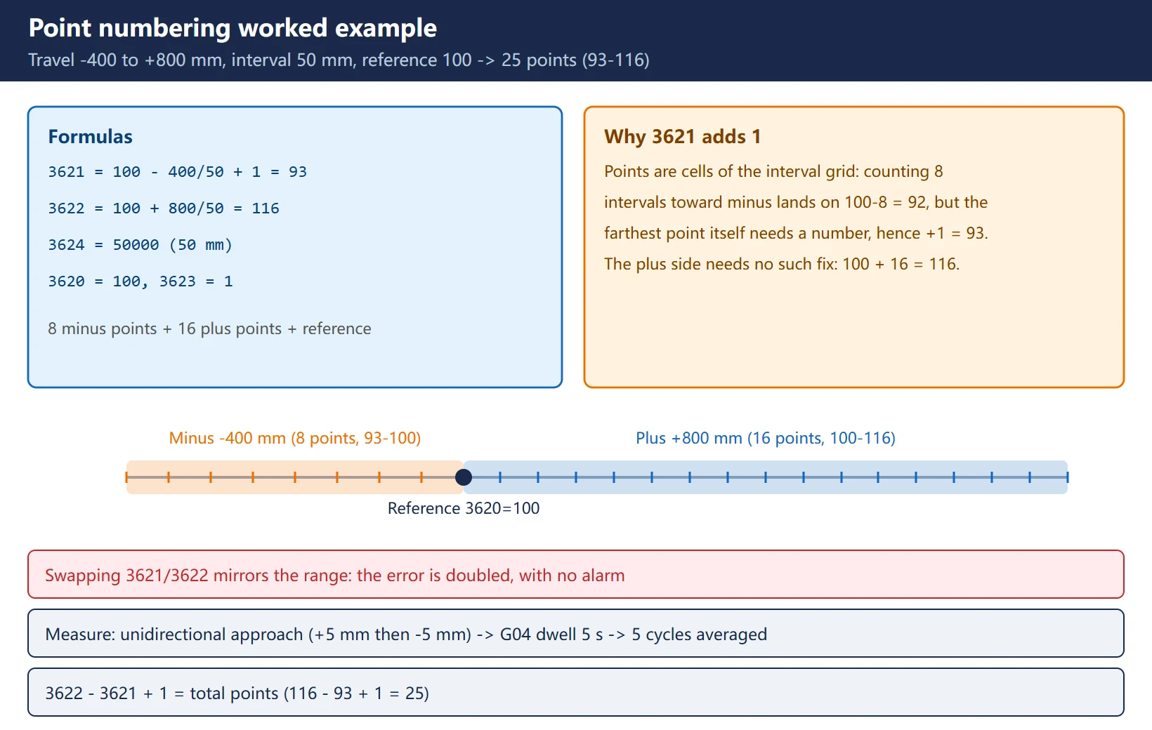
5. Parameter entry: 3620 / 3621 / 3622 / 3623 / 3624 / 3625
Table 5 i-series pitch compensation parameters, item by item
| Parameter | Meaning | Unit / range | Entry notes |
|---|---|---|---|
| 3620 | Compensation point number of the reference position | 0–1023 (or 3000–4023 block) | Reference point must be a compensation point; pick the number mid-stroke |
| 3621 | Most distant compensation point on the − side | 0–1023 | From the table above; must be < 3620 |
| 3622 | Most distant compensation point on the + side | 0–1023 | Must be > 3620; 3622 − 3621 + 1 = total points |
| 3623 | Compensation magnification | 1 (common) | The 0M ×1/×2/×4/×8 lives in 0011#1#0 — do not mix |
| 3624 | Compensation point interval | 0.001 mm, ≥ max feedrate ÷ 7500 | 50 mm is entered as 50000 |
| 3625 | Travel per revolution for a rotary-axis type | Rotary axes only | Leave empty on linear axes (section 9) |
Writing path is the same as backlash: MDI or E-stop → SETTING screen PARAMETER WRITE = 1 (P/S 100 is normal) → SYSTEM → PARAM → number → NO.SRH → enter → PWE back to 0. The compensation data itself is entered on the pitch compensation screen (SYSTEM → continuous menu → [PITCH] soft key), not the ordinary parameter screen — the place newcomers most often cannot find.
6. The sign trap: compensation data = measurement data negated, and it is incremental
Two rules; breaking either sends the compensation the wrong way:
- Sign: compensation data = measured data negated. If a point measures +5 µm ahead of command, enter −5.
- Form: enter increments, not absolute values. Each point takes the increment relative to the adjacent point on the − side (incremental value viewed toward the negative direction) — FANUC pitch compensation is incremental, and the official bidirectional manual states it as “always set incremental values as viewed in the negative direction”.
One measurement point spanning several compensation points: measurement spacing is usually wider than the compensation interval (e.g. measure every 20 mm with a 5 mm interval — one measurement point covers 4 compensation points). Spread that point’s compensation amount across its 4 points so the algebraic sum equals the measured compensation value. Official example: at −800.000 the measured deviation is 1 µm, so the compensation is −1, spread over 4 points as 0, −1, 0, 0 — not −1 in all four (that over-compensates fourfold).
Some models support a total-value input mode (0i-series parameter 3602#0 APE) where cumulative values are entered directly; whether you use it depends on your measurement software’s output format — confirm against your model’s manual.
7. Bidirectional compensation (3605#0): separate tables for each direction
Ordinary stored pitch compensation does not distinguish travel direction — both directions share one data set. Bidirectional pitch error compensation gives each direction its own table and, at reversal, computes the compensation from the data the way backlash does. It exists to fix “the + path and the − path do not coincide”, the classic semi-closed-loop symptom.
Table 6 Bidirectional pitch compensation extra parameters
| Parameter | Meaning | Notes |
|---|---|---|
| 3605#0 (BDP) | Bidirectional switch | 1: enabled; 0: disabled |
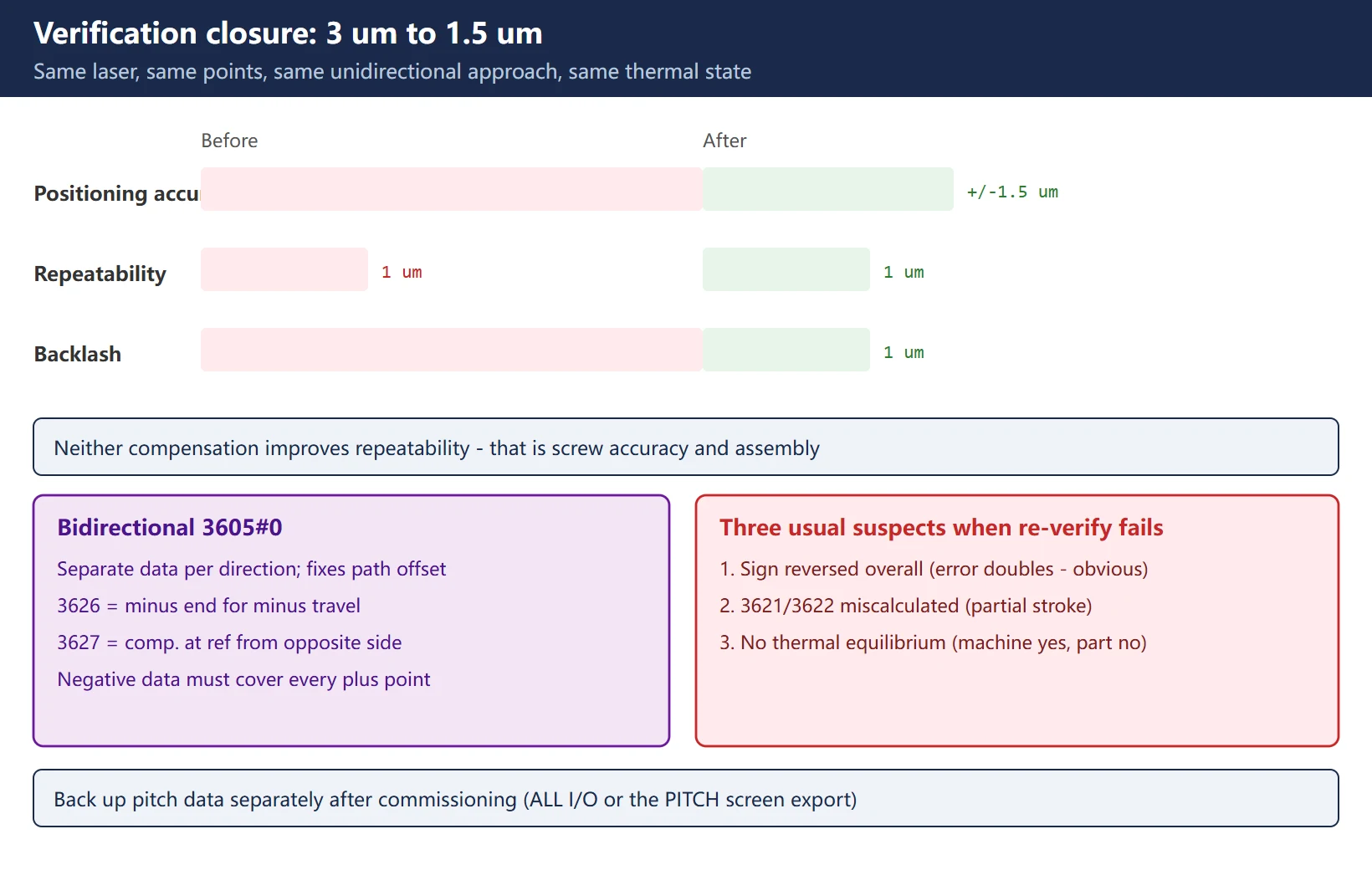
| 3626 | Most distant compensation point on the − side for travel in the − direction | Start of the negative-direction data area, independent of 3621 |
| 3627 | Compensation amount (absolute) at the reference position when reaching it opposite to the reference return direction | When manual reference return is positive, enter the negative-direction value |
| Data rule | Negative-direction data must cover every positive-direction point | Fill all points; same negative-direction increments |
Point numbers may use the 0–1023 and 3000–4023 blocks (0i-F: to 1535/4535); the two directions may share a block, but one axis must not span blocks.
8. Verification: how ±3 µm becomes ±1.5 µm
Re-verify with the identical method: laser interferometer, same points, same unidirectional approach, same thermal state. A published before/after comparison (X axis, same conditions):
Table 7 Before/after re-verification comparison
| Metric | Before | After | Note |
|---|---|---|---|
| Positioning accuracy | ±3 µm | ±1.5 µm | Halved — the accumulated error is flattened |
| Repeatability | 1 µm | 1 µm | Unchanged — pitch compensation does not improve repeatability |
| Backlash | 3 µm | 1 µm | That is 1851's job, shown here only to keep the two apart |
Three usual suspects when re-verification fails: ① the whole data set has the wrong sign (error doubles — obvious); ② the range 3621/3622 is miscalculated (only part of the stroke is compensated); ③ thermal equilibrium was not achieved (the data matches the machine but not the part). Back up the pitch compensation data separately after commissioning (ALL I/O, or export from the pitch screen) — it is an independent asset when the main board is replaced or data is restored.
9. Rotary axes vs linear axes
- 3625 is mandatory for rotary axes (travel per revolution); leave it empty on linear axes.
- Units become angular: compensation data is entered as angular values in detection units; under the IS-B standard the smallest detection unit can reach 0.001° (3.6″) — confirm against your model’s manual.
- Bidirectional on a rotary axis adds one more step: the point span per revolution must be reconciled against 3625; the numbering logic is the same as for linear axes.
- Measurement usually uses an angular reference (polygon / angle interferometer); the procedure is identical: unidirectional approach → dwell for counting → negate → enter as increments.
Frequently Asked Questions
Should FANUC pitch error compensation use a laser interferometer or a dial indicator?
Formal compensation must use a laser interferometer. A dial indicator measures single-point round-trip difference — fine for backlash (1851), which is single-point, bidirectional and direction-dependent. Pitch error is a full-stroke, position-dependent error requiring absolute position deviation collected point by point along the travel; a dial indicator’s range and resolution cannot do it. Without a laser on site, use a dial indicator plus gauge blocks at a few critical points to decide *whether* pitch compensation is needed — but the real data requires the laser. And measure with unidirectional approach (move +5 mm, come back −5 mm) so backlash is excluded from the data.
What do 3621 and 3622 represent, and why does swapping them break the compensation completely?
3621 is the most distant compensation point number on the − side and 3622 the most distant on the + side; together they define the compensated range. Swapped, the system reads a mirrored range — the point that should receive +5 µm receives −5 µm instead, doubling the original error with no alarm, exposed only at laser re-verification. Memorise the formulas: 3621 = reference number − (−travel ÷ interval) + 1; 3622 = reference number + (+travel ÷ interval).
Is backlash compensation still needed after pitch error compensation, and in what order?
Both are needed — they treat different faults: pitch compensation fixes full-stroke position error, backlash compensation fixes reversal lag; neither replaces the other. The order is backlash first, pitch second: ① measure and compensate 1851/1852 (or zero them); ② then measure and compensate pitch. Reversing the order lets the post-compensation change in backlash strip the pitch data of its baseline; ③ after pitch compensation, if bidirectional positioning differences are still large, go back and check 1851/1852. Neither compensation improves repeatability — that is mechanical.
Last updated: 2026-10-24
The original Chinese version — same procedure, with the full field notes.















暂无评论内容