


The most common “the program looks fine but the machine refuses to run” fault on a FANUC lathe: PS0041 INTERFERENCE IN G41/G42. The operator will say “wrong insert” — and swapping to a smaller nose radius does clear it — but the real cause is almost always a radial step smaller than 2× the tool nose radius (TNR).
This page covers the whole fault: which alarm number appears on which control, why the 2×TNR minimum step exists, the TNR matrix, the five cause families, and the parameter bits — including 5008#0, which one widely-read English site has backwards (it will get your interference check switched off). Every parameter bit below is quoted from FANUC’s own parameter manuals (0i-PB B-63980EN/01 and the 16i/18i Connection Manual).
Related: how the three tool compensation values (geometry / wear / radius) are managed on SINUMERIK 828D is covered in 828D Programming: Tool Offsets and Touch-off; the servo-side context is in FANUC Servo Gain 2021 / 1825.
1. What the alarm looks like: PS0041 / 0041 / 0325 by control
Table 1 G41/G42 alarm numbers by control (with official text)
| Number | Where it appears | Official alarm text | Source |
|---|---|---|---|
| PS0041 | 0i / 0i-D / 0i Mate-D: overcut in tool nose radius compensation | “In tool radius/tool nose radius compensation, excessive cutting may occur. Modify the program.” | 0i-D alarm list B-64305EN/03 |
| BG0041 / SR0041 | Same original number 0041 with the background-edit / RS232 prefix | Identical text | Same |
| PS0325 | Lathe: a G40/G41/G42 written inside a multiple repetitive canned cycle (G70/G71/G72/G73) | “Prohibited command in the contour” | Lathe operator's manual |
Correction one: “PS5400” is not this alarm. We could not verify PS5400 as the tool-compensation interference alarm in any official FANUC alarm manual; the correct number is PS0041 (shown as BG0041/SR0041 in some modes). If you see “PS5400”, go back to your machine’s own alarm list — chasing it as 0041 sends you the wrong way.
2. The one principle: why the radial step must be at least 2×TNR
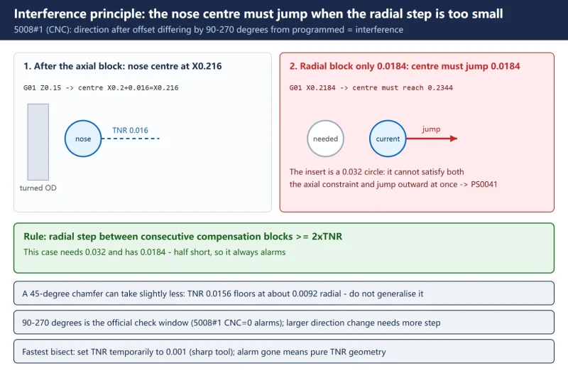
The official definition is buried in parameter 5008#1 (CNC): interference is judged when, after the offset is applied, the direction of movement differs from the programmed direction by between 90° and 270° (0: alarm issued; 1: no alarm). Here is why a small radial step triggers it, using a real case:
Turning OD with G41, TNR = 0.016″ (1/16 nose), block sequence:
G01 Z0.15(pure axial) — the imaginary nose centre sits at X0.2 + 0.016 = X0.216 (diameter value);G01 X0.2184(pure radial, diameter changes only 0.0184″) — the nose centre would have to jump to 0.2184 + 0.016 = 0.2344, an outward step of 0.0184″.
But the insert is a circle of radius 0.016″ (0.032″ wide): the nose centre cannot satisfy the previous axial constraint (hugging the already-turned cylinder) and jump 0.0184″ outward at the same time. The control computes that the compensation vector would have to reverse — which gouges the finished surface — and raises PS0041.
The rule: between two consecutive compensation blocks, the radial step must be at least 2×TNR. The example needs 0.032″ and has 0.0184″ — half of it, so the alarm is guaranteed.
A 45° chamfer can take slightly less: with TNR 0.0156″ and a 45° following move, the measured floor is about 0.0092″ radial — below 2×TNR (0.0312″), but do not treat the chamfer floor as a general value. For square transitions use the full 2×TNR.
3. TNR minimum-step matrix
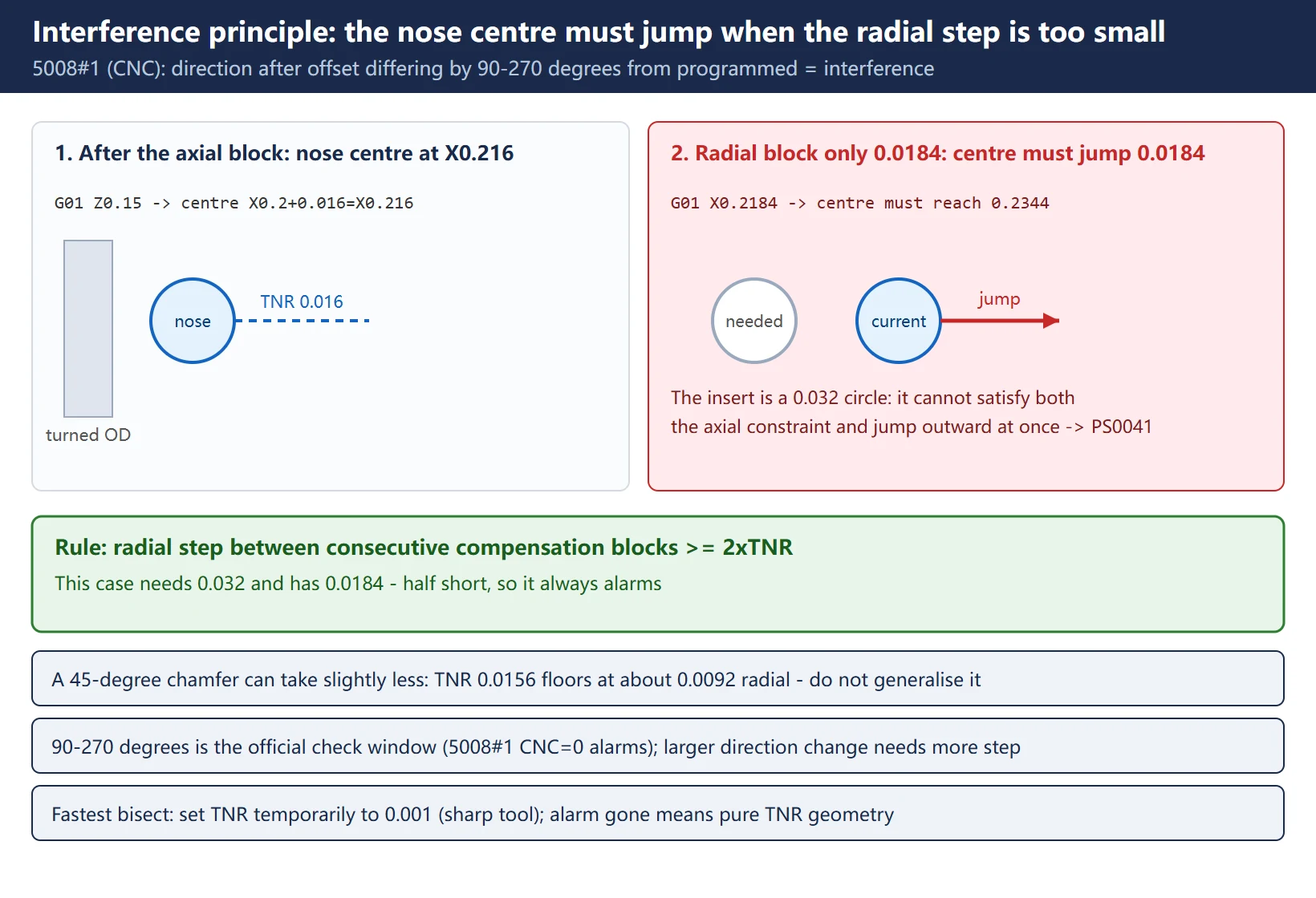
On a lathe with diameter-programmed X, read the matrix directly in programmed values (if your X is radius-programmed, halve the numbers — radius/diameter programming is set by machine data, confirm on the machine):
Table 2 TNR to minimum X step matrix (90-degree transition, diameter programming)
| Tool nose radius (TNR) | Minimum X step | Typical insert |
|---|---|---|
| 0.008″ (0.2 mm) | 0.016″ | 1/32 finishing |
| 0.016″ (0.4 mm) | 0.032″ | 1/16, most common |
| 0.031″ (0.8 mm) | 0.062″ | 1/32 heavy |
| 0.047″ (1.2 mm) | 0.094″ | 3/64 roughing |
| 0.004 mm | 0.008 mm | metric fine |
| 0.4 mm | 0.8 mm | metric common |
| 0.8 mm | 1.6 mm | metric heavy |
Bench rule: matrix value = TNR × 2.
4. The five cause families
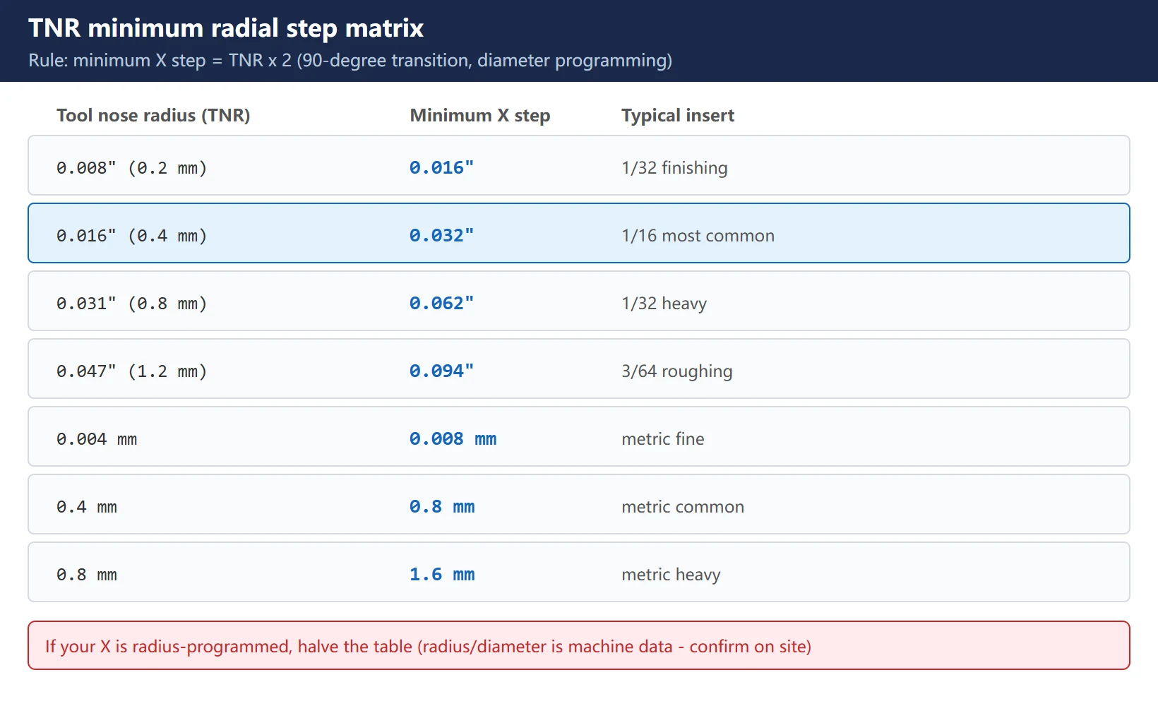
Table 3 Five cause families: symptom, first check, fix
| Cause | Typical symptom | First check | Fix |
|---|---|---|---|
| 1. Lead-in X step too small | Alarm on the 2nd–3rd block after G41/G42 engages | Compute each block's X delta against 2×TNR | Enlarge lead-in / intermediate radial moves to ≥2×TNR |
| 2. Arc in R format with a mislocated start | Alarm on a G02/G03 block; contour looks correct | R format lets the control fit a phantom centre | Re-run with explicit I/K |
| 3. Inside radius smaller than the nose | Boring a small hole / internal groove alarms | Compare the internal R with TNR | Smaller TNR insert, or re-design the feature |
| 4. Wrong T-register (imaginary tip number) | Alarm even on axial blocks; offset looks inverted | Match the offset table's T number to the physical tip orientation | Correct T (commonly 3/4/6/8/9) |
| 5. No G40 between tools | Alarm on the first compensation block after every tool change | Residual compensation vectors | Issue G40 at the end of each tool path; re-engage cleanly |
Two hidden high-frequency causes: the compensation value entered in the wrong unit (diameter typed where radius is expected — decided by 5004#0 ODI, and it overcuts instantly), and a stale R value in the offset table from the previous job (check the offset screen first).
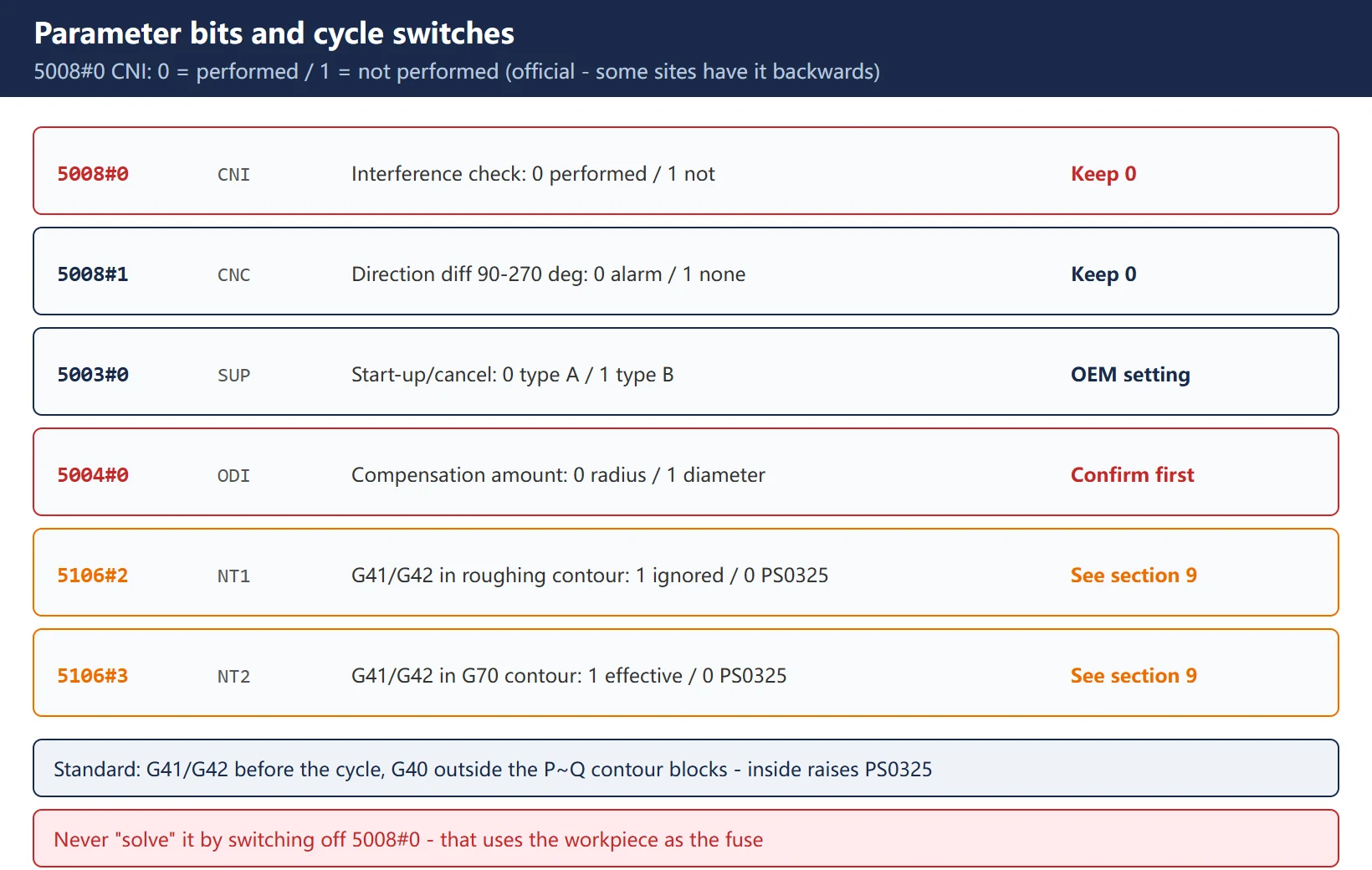
5. The parameter bits: why 5008#0 must not be switched off
Table 4 Tool compensation interference parameter bits (0i official manual)
| Bit | Name | Official definition | Recommendation |
|---|---|---|---|
| 5008#0 | CNI | Interference check for cutter compensation: 0 = performed; 1 = not performed | Keep 0 (default). Setting 1 removes the safety net |
| 5008#1 | CNC | During the interference check, when the movement direction after the offset differs from the programmed direction by 90°–270°: 0 = alarm; 1 = no alarm | Keep 0; OEM-only special cases |
| 5003#0 | SUP | Start-up / cancel in cutter compensation C: 0 = Type A; 1 = Type B | Machine-builder setting — do not change casually |
| 5004#0 | ODI | A cutter compensation amount is set using: 0 = a radius; 1 = a diameter | Confirm before entering any compensation value |
| 5106#2 | NT1 | G41/G42 written inside a roughing cycle contour (G71 etc.): 1 = ignored, no alarm; 0 = PS0325 | See section 9 |
| 5106#3 | NT2 | G41/G42 written inside the G70 contour: 1 = effective in G70; 0 = PS0325 | See section 9 |
Correction two: a widely-read English site states “5008#0 = 1 enables the interference check” — the opposite of the official manual. FANUC’s 0i-PB parameter manual (B-63980EN/01) defines CNI as 0: Performed / 1: Not performed. Following their advice sets the bit to 1 and switches the interference check off: the alarm goes quiet and the gouge goes straight into the part. Their “5008#2 selects Type B compensation” is also wrong — Type A/B is selected by 5003#0 (SUP); on 16i/18i, 5008#2 is the G39 corner-rounding switch.
6. Choosing between compensation types A/B/C
Table 5 FANUC series compensation types and look-ahead
| Series | Types available | Look-ahead blocks | Notes |
|---|---|---|---|
| 0i / 0i-Mate | A (5003#0=0) or B (=1) | 2 (basic) | Type A start-up/cancel is the lathe default |
| 0i-MF / 16i / 18i / 21i | A or B | 2 (A) / 5+ (B) | Type B looks further ahead; more forgiving on tight geometry |
| 30i / 31i / 32i | A / B / C | 2 / 5+ / 10+ | Type C is full look-ahead; handles very tight geometry with small TNR |
| Selection rule | — | — | The same program alarming on a 0i and running on a 30i is a look-ahead difference, not a program error |
Fastest field test: set TNR temporarily to 0.001″ (effectively a sharp tool). Alarm gone → it is TNR geometry, 100%, not a coordinate error. That is the fastest bisect you can run.
7. Cross-brand: 2×TNR is an ISO rule, not a FANUC quirk
Table 6 Cross-brand comparison
| Control | Alarm / behaviour | Compensation | Rule |
|---|---|---|---|
| FANUC 0i/16i/18i/30i | PS0041 / PS0325 | G41/G42, types A/B/C | Radial ≥ 2×TNR (ISO 6983) |
| SINUMERIK 840D sl / 828D | Contour monitoring alarms (e.g. 25050) | G41/G42 + CRC 3D/plane/contour | Same geometric constraint, different parameter set |
| Mitsubishi M80/M800 | Tool-compensation M01 alarm (G41.1/G42.1) | A or B | Same 2×TNR rule (one English site records a 2249 number group — not verified by us against an official manual; trust your machine's alarm text) |
The point: parameter numbers and alarm texts differ by vendor, but “radial step ≥ 2×TNR between consecutive compensation blocks” is the general geometric constraint of ISO 6983 tool nose radius compensation. Change controls and you change lookup tables, not physics.
8. Three verification methods
Table 7 Three verification methods
| Method | How | Finds | Limitation |
|---|---|---|---|
| 1. Graphic simulation | Program manager → Simulation with compensation display | Reversed tool path, insufficient lead-in | Depends on correct offset data |
| 2. Dry run with Z raised | Raise Z by 50 mm (or shift G54 Z) and dry-run | Where the vector vanishes / gouges in real motion | Slow; must be at a safe position |
| 3. Single-block stepping | Step through block by block; the alarm pins the block | The exact N-number | Needs supervision |
Acceptance after the fix: three consecutive first-article parts dimensionally stable, no 0041 recurrence, no witness marks. Never “solve” it by switching off 5008#0 — that uses the workpiece as the fuse.
9. G41/G42 inside G71/G70: the 5106#2 / 5106#3 switches
The FANUC lathe manual is explicit: with tool nose radius compensation, specify G41/G42 before the multiple repetitive canned cycle (G70/G71/G72/G73) and G40 outside the P-to-Q contour blocks; if G40/G41/G42 appears inside the G70/G71/G72/G73 command, PS0325 is issued.
Real machines show both behaviours, decided by parameters:
- G41/G42 inside a roughing cycle contour → 5106#2 (NT1): =1 the compensation command is ignored, no alarm; =0 raises PS0325.
- G41/G42 inside the G70 contour → 5106#3 (NT2): =1 compensation is effective during G70; =0 raises PS0325.
This answers the classic question “why does G71 roughing never alarm but G70 finishing does?” Two mechanisms: ① parameter behaviour — with NT1=1 the roughing contour’s G41/G42 is ignored (no alarm, but no compensation either), while NT2=0 in the G70 contour raises directly (note: G70 raises PS0325; if you see PS0041, compensation really was calculated); ② a step problem hidden by roughing — roughing passes have naturally large X steps, while finishing contours contain 0.00x” steps at chamfers and shoulders that blow up once compensation is real. Order of work: read 5106#2/5106#3 → move G41/G42 outside the cycle and G40 outside P~Q → verify every block’s X step against table 2.
Frequently Asked Questions
Is FANUC 0041 a wrong insert? Why does a smaller nose radius fix it?
Usually not “wrong” — it is a mismatch between nose radius and the programmed radial step. A smaller TNR lowers the 2×TNR threshold (0.016″ → 0.008″ moves the minimum step from 0.032″ to 0.016″), so your original 0.0184″ step suddenly passes — which proves the problem is the step, not the insert. The real fix: check every X step against the matrix, enlarge the lead-in/intermediate moves, or restructure the program. Swapping inserts “until it works” also drags in mismatched cutting data.
Can I switch off the interference check with parameter 5008#0?
No. The official definition is 5008#0 (CNI): 0 = check performed, 1 = not performed — several sources, including an English one, have this bit backwards; setting it to 1 per their advice disables the check. The alarm goes quiet and the gouge goes into the part with nothing left to stop it. Legitimate uses are OEM commissioning of a specific process, or a controlled test where you know exactly what you are doing. Production machines keep 0. If the bit mysteriously became 1, find out who changed the parameter before continuing production.
Why does G71 roughing never alarm, but G70 finishing raises PS0041?
Two common mechanisms: ① parameter behaviour — 5106#2 (NT1)=1 ignores G41/G42 inside the roughing contour (silent, and uncompensated), while 5106#3 (NT2)=0 in the G70 contour raises directly (though that one raises PS0325; PS0041 means compensation was genuinely being computed); ② the step problem masked by roughing — roughing X steps are naturally larger than 2×TNR, while finishing contours hide 0.00x” steps at chamfers and shoulders. Order of work: read 5106#2/5106#3 → normalise G41/G42 outside the cycle with G40 outside P~Q → verify each block’s X step against TNR.
Last updated: 2026-10-24

















暂无评论内容