


🚨 Scope and compliance:
IEC 60204-1(electrical equipment of machines, stop categories),ISO 13849-1(SRP/CS architecture categories and PL),IEC 61800-5-2(drive safety functions such as STO / SS1),ISO 13850(emergency stop design),ISO 12100(risk reduction hierarchy),IEC 62061(SIL) and related standards are copyright texts. This page only distinguishes concepts and gives lookup navigation; it reproduces no clause text and cites no clause numbers, so that second-hand summaries are not mistaken for the standard. Clause numbers and editions must be taken from the standards themselves and the machine documentation. The definitions of stop categories, the STO / SS1 mapping, common PL e / Cat 3 or 4 / SIL 3 design targets, the EDM definition and the reasons an ordinary PLC output cannot form a safety function come from the published JEMA functional-safety PLC guideline, drive manufacturer operating manuals and third-party safety engineering material. Quantified claims such as “single-channel STO is at most PL c” come from third-party material and were not verified against the standard text here; they are design hints, not compliance rulings. The achievable PL / SIL must be established by risk assessment, certified component data and whole-machine validation, and varies with machine type, local regulation and builder design. Wiring, modification and bypassing of safety circuits involve personal risk and must be performed by qualified personnel following the standards, the risk assessment and the builder’s written procedure, with records retained. This page is not wiring, selection or modification guidance, and offers no downloads, file mirrors, cloud drives or packaged archives of standards.
30-Second Triage: Identify Which Problem You Are Solving
| Question | Which system to open | First discrimination line |
|---|---|---|
| Should E-stop remove torque immediately or ramp down first | IEC 60204-1 stop categories 0 / 1 / 2 | Category 2 keeps power and cannot be used for E-stop |
| Dual channels, diagnostic coverage, achievable PL | ISO 13849-1 architecture categories B / 1 / 2 / 3 / 4 and PL a-e | Architecture categories are a different numbering system from stop categories |
How to use the STO / SS1 terminals on a drive | IEC 61800-5-2 drive safety functions | STO maps to stop category 0, SS1 to category 1 |
| Can an ordinary PLC transistor output drive STO directly | Qualification of devices in a safety-related control system | No; non-safety devices are not counted in PL calculations |
| Safety relay reports a cross fault and will not reset | Dual-channel consistency and EDM feedback | Check both inputs and external contact feedback |
| Vertical axis drops after E-stop | Stop category and mechanical brake | STO does not prevent gravitational drop |
Table 0. Six problem classes and the first discrimination line
Fanuc Emergency Stop Circuit covers the signal chain and “reset but still not ready”, while Heidenhain TNC Guard Doors Are Open covers four-layer safety-chain localisation; both are troubleshooting oriented. This page only classifies concepts and does not replace machine-specific diagnosis.
1. Two Kinds of Category: Stop 0/1/2 versus Architecture B/1/2/3/4
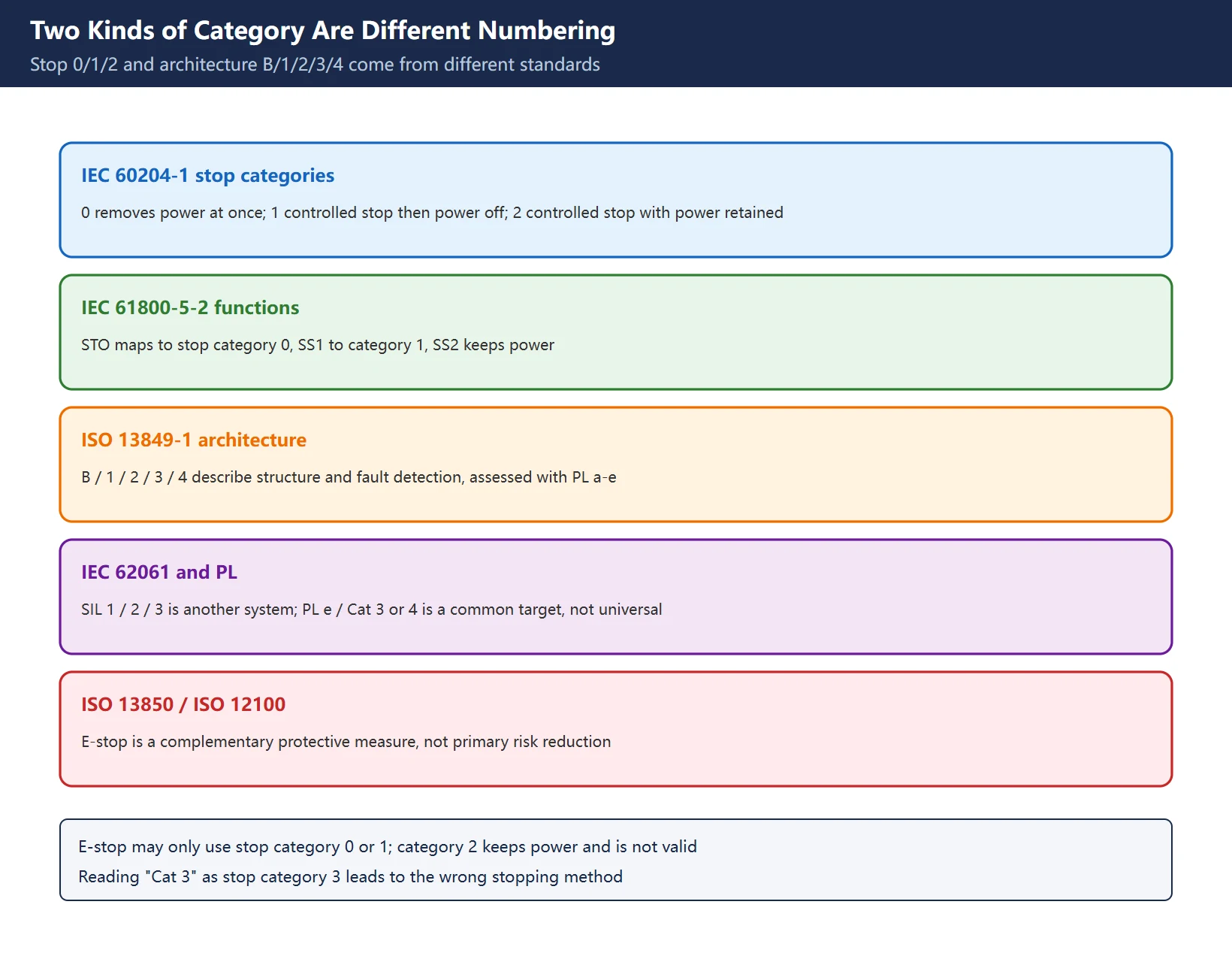
This is the main correction to the circulating brief, which lists “Cat0 / Cat1 / Cat2 / Cat3 criteria” under “defined by ISO 13849”. Those are two different concepts in two different standards.
| System | Numbering | What it describes | Typical values | Common misuse |
|---|---|---|---|---|
| IEC 60204-1 stop categories | 0 / 1 / 2 | How the machine stops and when power is removed | 0: immediate power removal; 1: controlled stop then power removal; 2: controlled stop with power retained | Treating category 2 as valid for E-stop |
| IEC 61800-5-2 drive safety functions | STO / SS1 / SS2 and others | Which safety function the drive implements | STO maps to stop category 0, SS1 to category 1 | Reading STO as “stop and hold position” |
| ISO 13849-1 architecture categories | B / 1 / 2 / 3 / 4 | Structure and fault-detection capability of the safety-related control part | Assessed together with PL a-e | Reading “Cat 3” as stop category 3 |
| IEC 62061 | SIL 1 / 2 / 3 | Failure-probability level of safety-related control systems | Related to PL but a separate system | Writing “SIL 3 is mandatory on every machine” |
| ISO 13850 / ISO 12100 | Principles | E-stop design principles and the risk reduction hierarchy | E-stop is a complementary protective measure, not the primary risk reduction | Assuming risk is controlled because an E-stop is fitted |
Table 1. Five conceptual systems in separate columns
One directly applicable rule: an E-stop may only use stop category 0 or 1, because both end with power removed; category 2 leaves power available at standstill and carries a restart-on-fault risk. Meanwhile “PL e / Cat 3 or 4 / SIL 3” is a common design target for industrial drive integration, not a universal requirement — the required level comes from the risk assessment. Third-party material suggests a single-channel STO reaches roughly PL c and that a dual-channel safety relay driving dual STO inputs is the conventional route to higher levels; such quantified claims must be checked against the standard text and component certificates, and are not ruled on here.
2. STO versus SS1: The Real Difference Between Category 0 and 1
| Dimension | STO (Safe Torque Off) | SS1 (Safe Stop 1) |
|---|---|---|
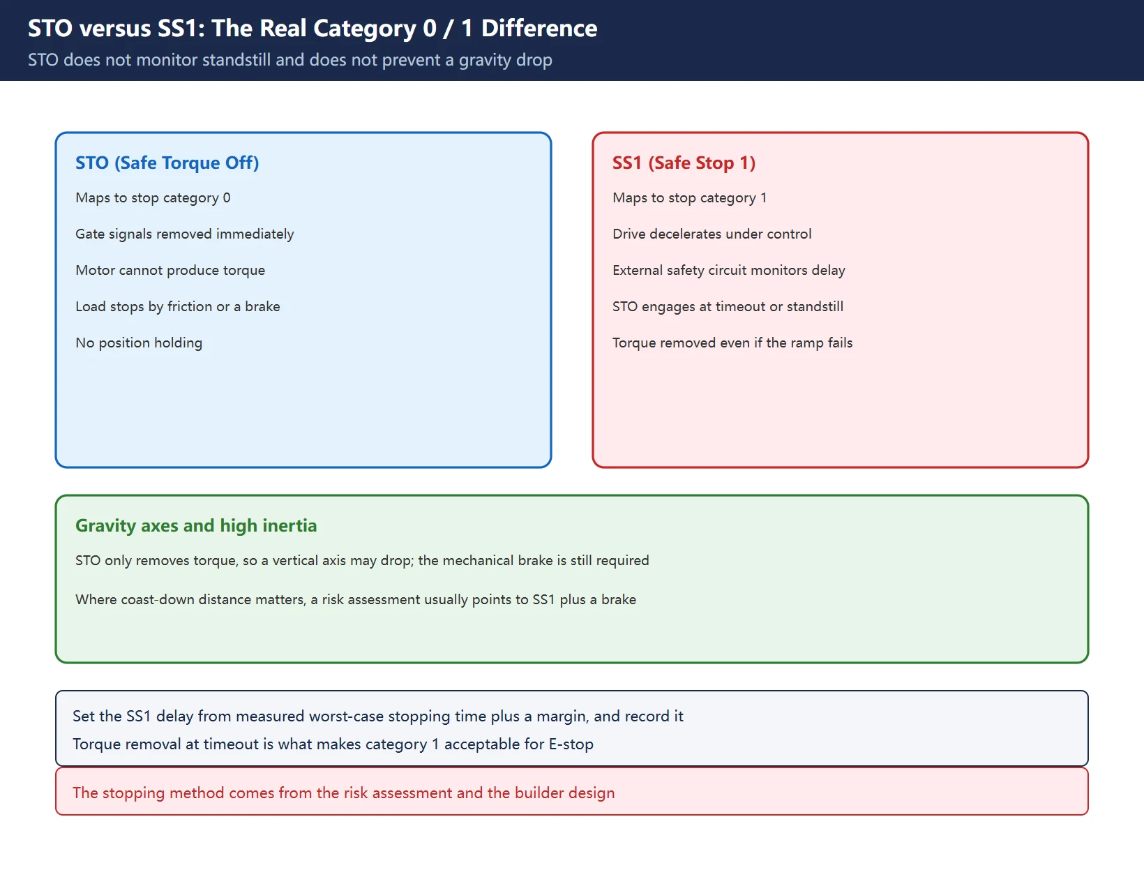
| Corresponding stop category | Category 0: immediate removal of power to actuators, uncontrolled stop | Category 1: controlled stop with power available, then power removed |
| Drive behaviour | Gate signals to the output stage are removed so the motor cannot produce torque | Drive ramps down, an external safety circuit monitors a delay, then STO engages at timeout or standstill |
| Standstill monitoring | Not provided; no position holding | Ramp is monitored; STO still removes torque at the end |
| Vertical / gravity axis | Coasting or gravitational drop is handled by a mechanical brake; STO itself does not prevent it | Often selected when inertia coast-down distance matters, but the brake is still required |
| If the controlled stop fails | Not applicable | Torque must still be removed when the safety delay expires; this is what makes category 1 acceptable for E-stop |
| Basis of the delay setting | Not applicable | Measured stopping time at worst-case load plus a margin, recorded in the validation file |
Table 2. Six differences between STO and SS1
The classic field misreading is “STO fitted means the machine stops safely”: STO only stops producing torque, so a high-inertia spindle may coast for a long time and a vertical axis may drop. The stopping method therefore comes from the risk assessment, not from the parts list. Brake timing on gravity axes is covered in Fanuc Gravity-Axis Brake, and the Siemens side in 840D sl Safety Integrated Alarms.
3. Four Architectures: Who Makes the Final Decision
| Architecture | Decision device | Achievable level direction | Advantage | Cost and boundary |
|---|---|---|---|---|
| Dedicated safety relay | Dual-channel relay with force-guided contacts | Depends on certificates and dual-channel wiring; covers most single-function cases | Fixed logic, straightforward wiring, bypass requires physical rewiring and is visible at audit | Wiring grows quickly with logic complexity |
| Safety PLC / safety bus | Certified safety PLC with PROFIsafe, CIP Safety, Safety over EtherCAT and similar | High levels remain achievable with complex logic | Many safety functions in one place, rich diagnostics | Needs a certified development process, version control and validation records |
| Ordinary PLC transistor output | One general-purpose PLC output | Cannot form a safety function | Lowest cost, easy to reprogram | Single-channel faults undetectable, no self-test, failure rates uncertified, excluded from PL; bypass is one ladder edit |
| Hybrid | Safety circuit decides; ordinary PLC receives read-only status | Determined by the safety circuit | Host can display, log and “request a stop” | Ordinary PLC may request but must not veto; software watchdogs and heartbeats are not accepted in formal assessment |
Table 3. Four architectures compared
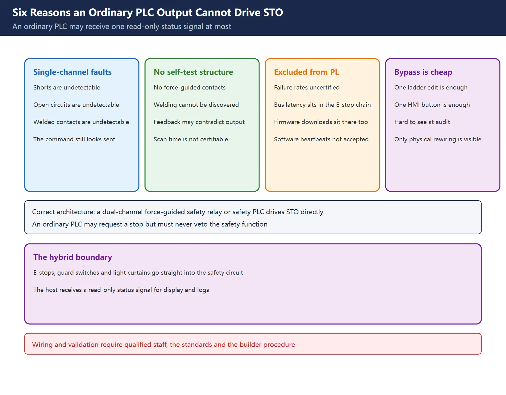
The hybrid row is the one most often written incorrectly. The safety circuit (relay or safety PLC) takes E-stops, guard interlocks and light curtains directly and drives the STO inputs directly; the host or ordinary PLC receives one status output for logging and may issue a soft-stop request, but cannot prevent the safety circuit from triggering a stop. That “read-only status, never veto” boundary has a counterpart in How to Use FANUC PMC Force Output: forcing a signal is a diagnostic tool, not a substitute for a safety function.
4. Why an Ordinary PLC Output Cannot Drive STO
| Reason | Concrete failure mode | What the safety circuit provides instead |
|---|---|---|
| Single-channel faults are undetectable | Output short, open circuit or welded contact still looks like the stop command was sent | Dual channels, cross-fault detection and a safe state on disagreement |
| No force-guided contacts or self-test | A welded ordinary relay contact cannot be discovered by logic | Force-guided contacts mechanically link NO and NC states |
| Timing is not certifiable | Scan time, bus latency and firmware downloads sit between E-stop contact closure and STO de-energising | Hardwired safety circuit independent of the CNC program and fieldbus |
| Failure rates are excluded from PL | General-purpose PLC failure data is not functionally safety certified | Only certified component PFHd / MTTFd enters the PL calculation |
| Bypass is cheap | One ladder edit or one HMI button removes the safety function | Bypass needs physical rewiring and is immediately visible at audit |
| Software “safety” is not accepted | Watchdogs, heartbeats, host ROS nodes | Useful engineering value, but no substitute in formal assessment |
Table 4. Six reasons it cannot be wired that way
One more principle is often missed: E-stop is a complementary protective measure, not the primary means of risk reduction. Risk reduction comes from inherently safe design, guards and the safety functions themselves. E-stop buttons must latch and use a positive-opening (direct-opening) contact structure, and the reset action alone must not restart the machine; verify these principles in the standards and the builder’s documentation, since no clause numbers are quoted here. The CNC-side signal chain is described in Fanuc Emergency Stop Circuit.
5. Dual Channels, Force-Guided Contacts and EDM
| Element | Purpose | If omitted |
|---|---|---|
| Two normally closed channels | One channel can still cut power when the other fails, and disagreement is detectable | A single fault loses the safety function |
| Positive-opening E-stop button | Mechanical structure forces the contact open, independent of springs or electronics | A welded or jammed contact makes the button ineffective |
| Force-guided relay contacts | NO and NC contacts are mechanically linked, so the feedback contact is trustworthy | Feedback can contradict the real output state |
| Cross-short detection | Detects shorts between the two channels and cross-wiring | Safety relay reports a cross fault and refuses to reset |
| EDM (External Device Monitoring) | Safety relay or safety PLC reads back the real state of external contactors and drives, and stops its output on a discrepancy | If an external device does not open as expected, the fault latches and re-enable is refused |
| Status signal as read-only uplink | Feeds PLC / HMI display and logs | If writable, it creates a path for a non-safety system to veto the safety function |
Table 5. Six elements and the consequence of omitting each
EDM is defined in the JEMA functional-safety PLC guideline as follows: external devices such as E-stop switches and magnetic contactors have no self-diagnostic function of their own, so the safety controller checks their actions and stops its output if anything is abnormal — also called back-check. The typical “what happens if I omit it” symptom is: the safety output has opened but the drive feedback never returns, so the relay latches a fault and no amount of resetting enables the machine. That is the same trap as “PLC shows E-stop OK but the drive never powers up” in Fanuc Emergency Stop Circuit: a status word is not the real safety output state.
6. Commissioning and Periodic Tests
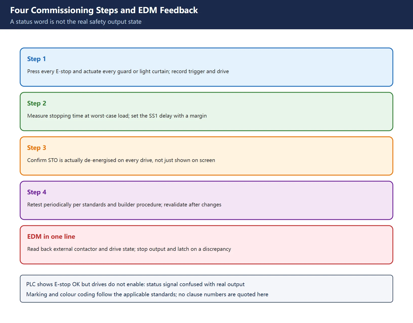
| Step | Action | What to record |
|---|---|---|
| 1 | Press every E-stop button and actuate each guard switch or light curtain, confirming each one triggers | Trigger point and corresponding drive object |
| 2 | Measure stopping time at worst-case load, set the SS1 delay with a margin | Measured value, delay setting and its basis |
| 3 | Confirm the STO inputs of every relevant drive are actually de-energised, not just that the screen shows E-stop | State and measurement point for each drive |
| 4 | Retest periodically and after any modification, following the standards and the builder's procedure | Test date, results, deviations and corrective actions |
Table 6. Four commissioning steps and the record
Three boundaries. First, stopping time must be measured rather than copied from a datasheet; the delay must cover worst-case load, and a failed ramp must still end with torque removed by the safety timeout. Second, marking, colour coding and documentation requirements follow the applicable standards and the builder’s design; no clause numbers are quoted here so that second-hand notes are not mistaken for the standard. Third, for nuisance trips in thunderstorm season or intermittent cross faults, check surge protection, shielding and dual-channel wiring before replacing components. Reading the relevant drawings is covered in How to Read a CNC Machine Electrical Schematic.
7. Common Fault Readings and Site Index
Table 7. Nine symptoms and further reading
Frequently Asked Questions
What is the difference between STO and SS1, and when is SS1 required?
STO corresponds to IEC 60204-1 stop category 0: gate signals to the drive output stage are removed immediately, the motor produces no torque, and the load stops through friction or a mechanical brake; it does not monitor standstill and does not prevent a vertical axis from dropping. SS1 corresponds to category 1: the drive decelerates under control, an external safety circuit monitors a delay, and STO engages at timeout or standstill; even if the ramp fails, torque must still be removed when the safety delay expires, which is why category 1 is acceptable for an E-stop. When coast-down distance of a high-inertia load is unacceptable, or a gravity axis has significant drift, a risk assessment will usually point to SS1 plus a mechanical brake rather than STO alone. The stopping method is determined by the risk assessment and the builder’s design, not ruled on here.
Can an ordinary PLC transistor output be wired directly to a drive STO input?
No. A short, open circuit or welded contact on a single output cannot be detected, and an ordinary relay has neither force-guided contacts nor self-test. PLC scan time and bus latency fall between E-stop contact closure and STO de-energising, and general-purpose PLC failure rates are not functionally safety certified, so they cannot enter a PL calculation. Software watchdogs, heartbeats and host nodes are not accepted in formal assessment, and bypassing takes a single ladder edit. The correct architecture uses a safety relay or safety PLC with dual-channel, force-guided outputs driving the STO inputs directly, while an ordinary PLC receives at most one read-only status signal for display and logging: it may request a stop but must never veto the safety function. Wiring, selection and validation must be performed by qualified personnel following the standards, the risk assessment and the builder’s procedure.
What does EDM feedback do in a safety circuit, and what happens if it is omitted?
EDM (External Device Monitoring) is the safety relay or safety PLC reading back the real state of external devices: E-stop switches, magnetic contactors and drives have no self-diagnostic capability of their own, so the safety controller checks their actions through auxiliary contacts and stops its output when anything is abnormal. Omitting or miswiring it is a common reason a safety relay reports a cross fault and refuses to reset or re-enable. Also note that a status word is not the real output state: a PLC screen showing E-stop OK does not prove that every drive’s STO input is de-energised. Commissioning therefore means pressing each E-stop, measuring real stopping time, verifying STO de-energising on every drive, and retesting periodically with records, following the standards and the builder’s procedure. No clause numbers are quoted here; use the standards themselves for those.
Last updated: 2026-11-15
Where to go next
- FANUC Troubleshooting — the full guide library: alarms, diagnosis numbers, servo, spindle, PMC and electrical faults, organised by symptom.
- CNC Repair Tools — which instrument measures what: multimeters, clamp meters, insulation testers and oscilloscopes, with the specification that actually matters.
- Remote Technical Support — have the readings reviewed with you: alarm reverse lookup, PMC ladder analysis and servo tuning advice by call. Repair companies and integrators welcome.
Read the guide, get the right instrument, or walk the diagnosis through with someone — pick whichever you need.
The original Chinese version — same procedure, with the full field notes.
















暂无评论内容