


Sister article: Proximity switches NPN / PNP / NAMUR for machine tools – the Chinese guide; related: How to read a CNC machine electrical schematic, Machine safety circuits: STO vs SS1 and dual channels, CNC homing failure classification, Fanuc I/O Link address assignment, Spindle unclamp failure: PMC input signal chain, CNC 24 V / 5 V control power faults.
17.1 Verdict first: default to PNP for new installs, NPN only for legacy retrofits
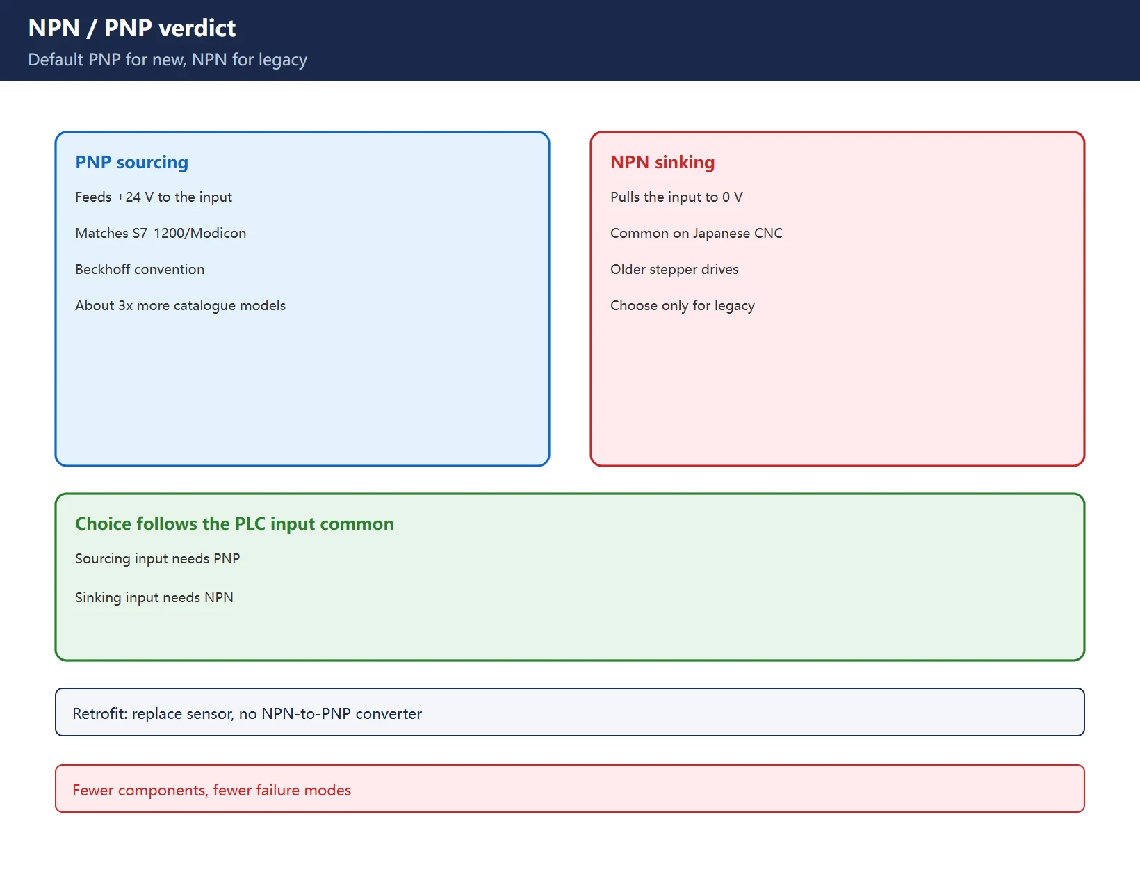
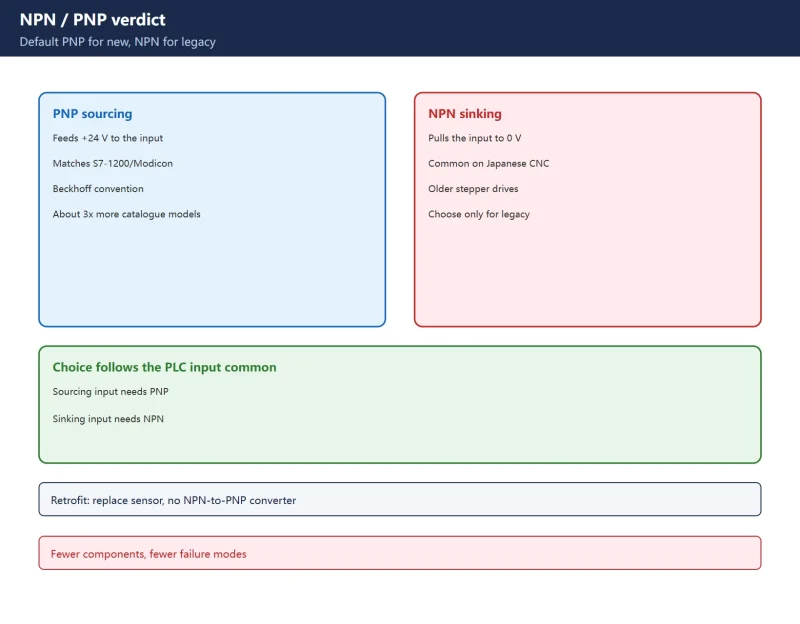
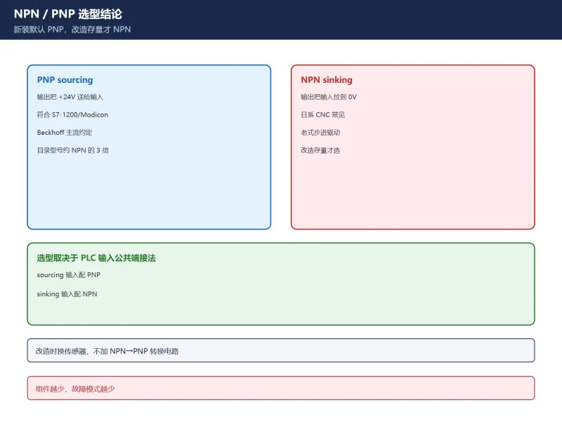
- PNP (sourcing) switches +24 V to the input and matches the sourcing-input convention of mainstream PLCs such as Siemens S7-1200, Schneider Modicon and Beckhoff. Catalogues carry roughly three times as many PNP as NPN models (one major brand lists about 207 PNP series versus 74 NPN).
- NPN (sinking) pulls the input to 0 V and is common on Japanese CNC controls and older stepper drives.
- The choice depends on the PLC input common: sourcing inputs need PNP, sinking inputs need NPN. On a retrofit, replace the sensor rather than adding an NPN-to-PNP converter – fewer components, fewer failure modes.
Table 1. NPN / PNP selection (follow the PLC input type)
17.2 The three output families
| Family | Wiring | Output behaviour | Typical use |
|---|---|---|---|
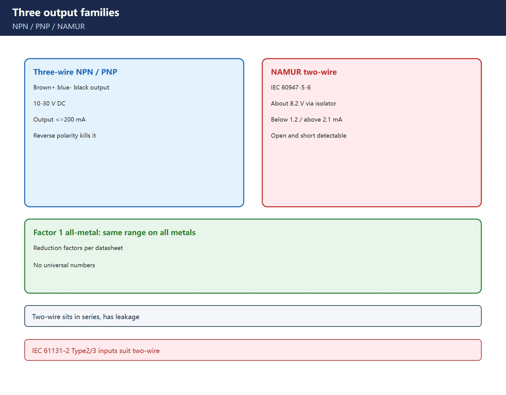
| NPN (sink) | Brown + / blue – / black output | Pulls the load to 0 V | Japanese CNC, legacy steppers |
| PNP (source) | Brown + / blue – / black output | Feeds +24 V to the load | European PLCs, new machines |
| NAMUR (IEC 60947-5-6) | Two-wire, about 8.2 V via an isolating amplifier | Current draw below 1.2 mA / above 2.1 mA | Intrinsically safe loops, Ex zones |
| Four-wire complementary | One NO plus one NC | Both states available | Series safety chains |
Table 2. Output families (four-wire is a variant; check the datasheet)
Two-wire sensors sit in series like a mechanical switch but have leakage current and an on-state voltage drop: the PLC input must tolerate them (IEC 61131-2 Type 2/3 inputs do) or the input may never turn off. The key NAMUR advantage is that wire breaks and shorts are detectable – current still flows in the low state, so a monitoring loop can see an open circuit.
17.3 The three machine roles (the focus of this guide)
1. Hard limit – prefer normally closed (NC)
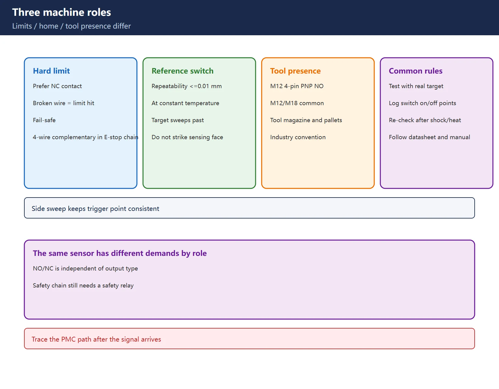
A broken wire then reads as “limit triggered” – that is fail-safe: the machine stops rather than losing protection. Four-wire complementary types (one NO, one NC) or PNP/NPN NC sensors wired in series into a single E-stop chain are the mainstream architecture for industrial machine safety circuits. See machine safety circuits for the chain design.
2. Reference / home switch – repeatability is what matters
At constant temperature, repeatability is typically ≤0.01 mm, adequate for stepper and servo reference return. Mount the target so it sweeps past the sensor rather than striking the sensing face – consistent side-swipe triggering reduces mechanical shock and improves repeatability. For home-failure diagnosis see homing failure classification; for inputs being missed see I/O Link addressing.
3. Tool / workpiece presence – M12 4-pin PNP NO is the industry convention
On automatic tool changers and pallet changers, M12 / M18, PNP, NO and 4-pin connectors are the common configuration. For the PMC-side signal path see spindle unclamp / tool not seated.
Table 3. Selection by role (part numbers follow the machine builder and datasheet)
17.4 Three corrections to sensing distance
Rated distance Sn applies only to a standard mild-steel target:
- Copper / aluminium is roughly 30-50% of steel (aluminium about 0.4, copper about 0.3 – use the reduction factor in the datasheet); small or thin targets reduce it further.
- A non-flush sensor needs at least 2 x Sn of free space around the sensing face; mounting it flush in a steel bracket leaves it permanently triggered.
- On stainless or aluminium panels, use the maker’s flush-mount accessory or a non-flush type rated around 2.2 x Sn.
For consistent distance across mixed metals, choose a Factor 1 (all-metal) sensor. All reduction factors follow the manufacturer datasheet – no universal numbers.
17.5 Wiring and supply
Three-wire sensors commonly use 10-30 V DC: brown +, blue -, black output; reverse polarity destroys the sensor. Output current is typically ≤200 mA, enough for a relay or PLC input. Two-wire types need attention to leakage and minimum load current; NAMUR must use an isolating amplifier, never a plain PLC input.
17.6 Three EMC rules
- Keep at least 300 mm from variable-frequency drives;
- Route power and signal cables separately;
- Add 0.1 uF across the PLC input to suppress spikes (per input circuit and maker recommendation).
For grounding and shielding practice see SV0381 linear scale alarms caused by poor grounding.
17.7 Four checks for intermittent operation
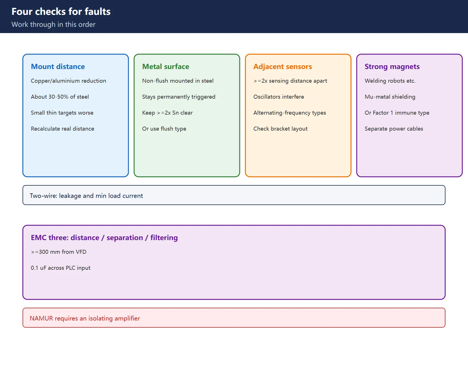
- Wrong mounting distance – especially on copper/aluminium, recalculate with the reduction factor;
- Metal mounting surface shortens the range – check whether a non-flush type was mounted flush;
- Adjacent sensors interfering – allow at least twice the sensing distance between them, or use alternating-frequency models;
- Strong magnetic sources (welding robots) – use Mu-metal shielding or a Factor 1 magnet-immune type.
17.8 Magnet selection and mounting
For magnet actuation, neodymium iron boron 15 x 5 mm with a field of at least 800 Gauss is a common starting point (follow the supplier spec). Keep axial alignment within ±3 degrees and radial spacing within 80% of nominal. Magnet specifications vary widely by brand.
17.9 Retrofit advice: replace the sensor, do not stack converters
When converting a legacy NPN installation to PNP, replace the sensors instead of adding NPN-to-PNP converter circuits. Every extra module is another failure point. If the old wiring must stay, verify the PLC input common first, then choose PNP or NPN accordingly.
17.10 Commissioning and acceptance
With the real target, verify and record both the switch-on and switch-off points in the machine log; re-check after insertion, vibration and temperature changes. Acceptance items are covered by the 30-point used-machine electrical checklist and CNC 24 V / 5 V control power faults.
Frequently Asked Questions
What is the difference between NPN and PNP proximity switches, and which should a new machine use?
PNP (sourcing) feeds +24 V to the input, NPN (sinking) pulls it to 0 V; that describes the output transistor and says nothing about NO/NC. The choice follows the PLC input common: sourcing inputs need PNP, sinking inputs need NPN. New installs default to PNP because it matches mainstream European PLCs and is far more available; choose NPN only for legacy Japanese equipment.
Why should a machine hard-limit switch be normally closed?
Because an open cable is the most likely failure in a limit loop. With NC topology, a broken wire reads as “limit triggered” and the machine stops – that is fail-safe. With NO, a broken wire reads as “not at limit” and protection is silently lost. The overall chain still needs a safety relay.
What happens if a reference switch is mounted crooked, and what repeatability is realistic?
A crooked mount makes the trigger point inconsistent, so the home position drifts with each return. At constant temperature an inductive switch typically reaches ≤0.01 mm repeatability (check the datasheet). Mount the target so it sweeps past the sensor side rather than striking the sensing face, keeping the trigger point consistent.
Last updated: 2026-11-19
Where to go next
- FANUC Troubleshooting — the full guide library: alarms, diagnosis numbers, servo, spindle, PMC and electrical faults, organised by symptom.
- CNC Repair Tools — which instrument measures what: multimeters, clamp meters, insulation testers and oscilloscopes, with the specification that actually matters.
- Remote Technical Support — have the readings reviewed with you: alarm reverse lookup, PMC ladder analysis and servo tuning advice by call. Repair companies and integrators welcome.
- Buying & Ownership Decisions — refurbished vs new, used-machine checks, software licensing and manuals: spend with the field facts in hand.
Read the guide, get the right instrument, or walk the diagnosis through with someone — pick whichever you need.
The original Chinese version — same procedure, with the full field notes.






















暂无评论内容