


Sister article: How to read SINAMICS F codes: what 230020 means on an 828D. Related: SINAMIC trigger alarm localization, 828D sign-of-life alarm 2000/2001, 828D common machine data quick reference, following error and contour error tuning.
1.1 Get the two numbers to line up first
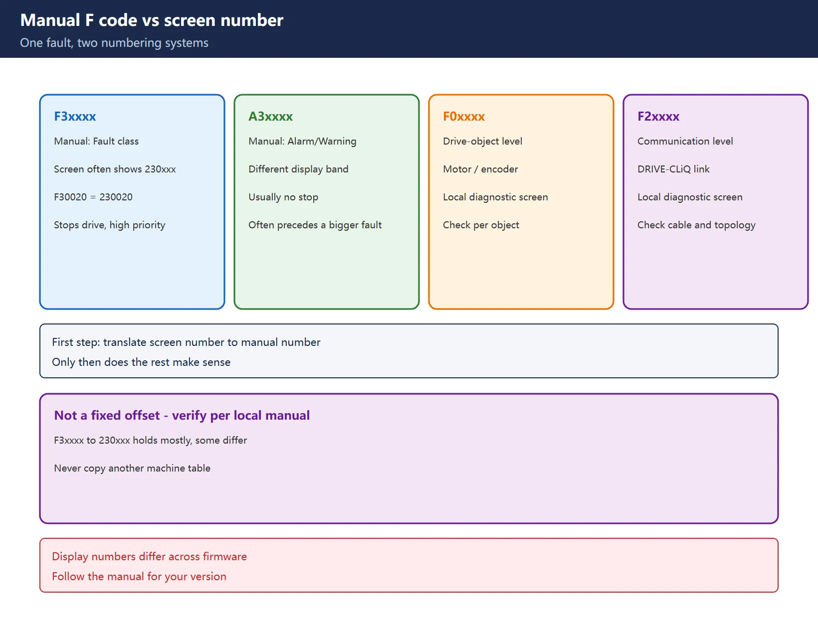
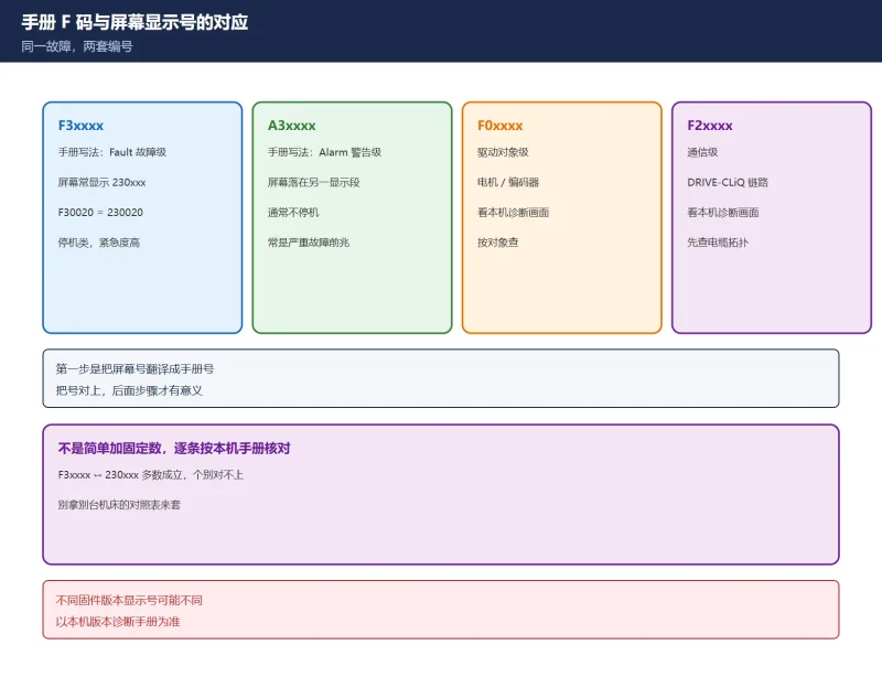
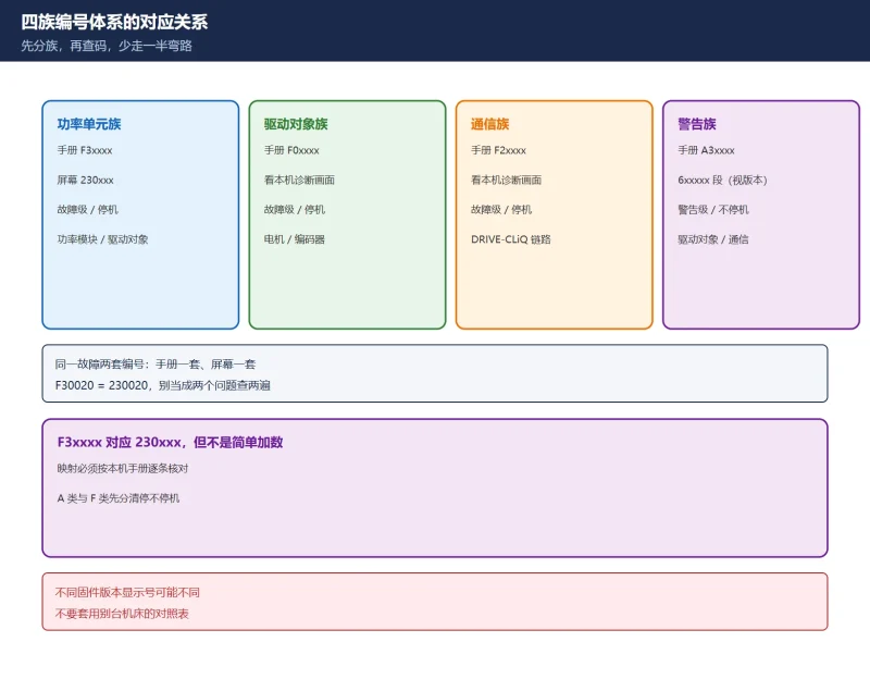
The first step is not opening the manual – it is translating the screen number into the manual number:
- The manual writes
F3xxxx(F = Fault, stops the drive); a 828D screen often shows a six-digit230xxx– e.g.F30020 ↔ 230020,F30021 ↔ 230021; A3xxxx(A = Alarm/Warning) usually does not stop the machine and appears in a different display band;F0xxxxis drive-object level (motor, encoder),F2xxxxis communication level (DRIVE-CLiQ).
Discipline: F3xxxx → 230xxx holds on most 828D systems, but it is not a fixed numeric offset; some codes and versions do not match. Verify each against the manual for your own version; never copy another machine’s table. The rest of the process only makes sense once the number is right.
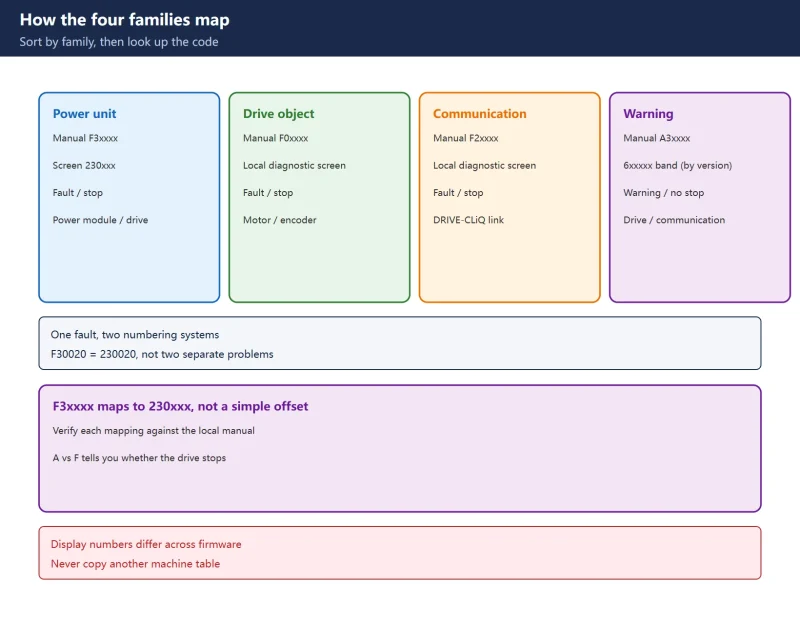
1.2 Locate the family first: power unit / drive / motor / communication
Once you have the F code, identify its family before looking up the specific entry:
| Family | Typical codes | Owned by | First landing point |
|---|---|---|---|
| Power unit | F30001 / F30011 / F30020 / F30021 | Power module, DC link | Check wiring, configuration, DC bus |
| Drive | F07011 / F07012 | Drive itself | Check cooling, overcurrent, parameters |
| Motor / encoder | F31100 / F31110 | Motor, encoder | Check encoder cable, topology |
| Communication | A30010 / F2xxxx | DRIVE-CLiQ link | Check cable, connectors, 24 V |
Table 1. Sort by family before looking up the code – it removes half the wasted diagnosis
Family matters because it decides what to check first: power-unit faults start with wiring and configuration, communication with cable and topology, drive with cooling and load. Get the family wrong and you will search further and further from the fault.
1.3 F30020 configuration not supported: fix configuration, not hardware
F30020 (screen 230020) means “the requested function is not supported by the current configuration” – a configuration problem, not a hardware failure. The low four bits of the fault value point to different causes: autonomous run request, DRIVE-CLiQ timing not permitted, PM260 with PS-ASIC version combination, initialization not complete, excessive current-loop dynamic request, firmware incompatibility.
Field path: read the fault value -> decide configuration / timing / firmware -> change the matching setting -> do a POWER ON (configuration changes need a POWER ON; a plain reset does not apply them). Do not start by replacing the power module – the classic misdiagnosis for this alarm.
1.4 F30021 ground fault: r0949 decides cable versus module
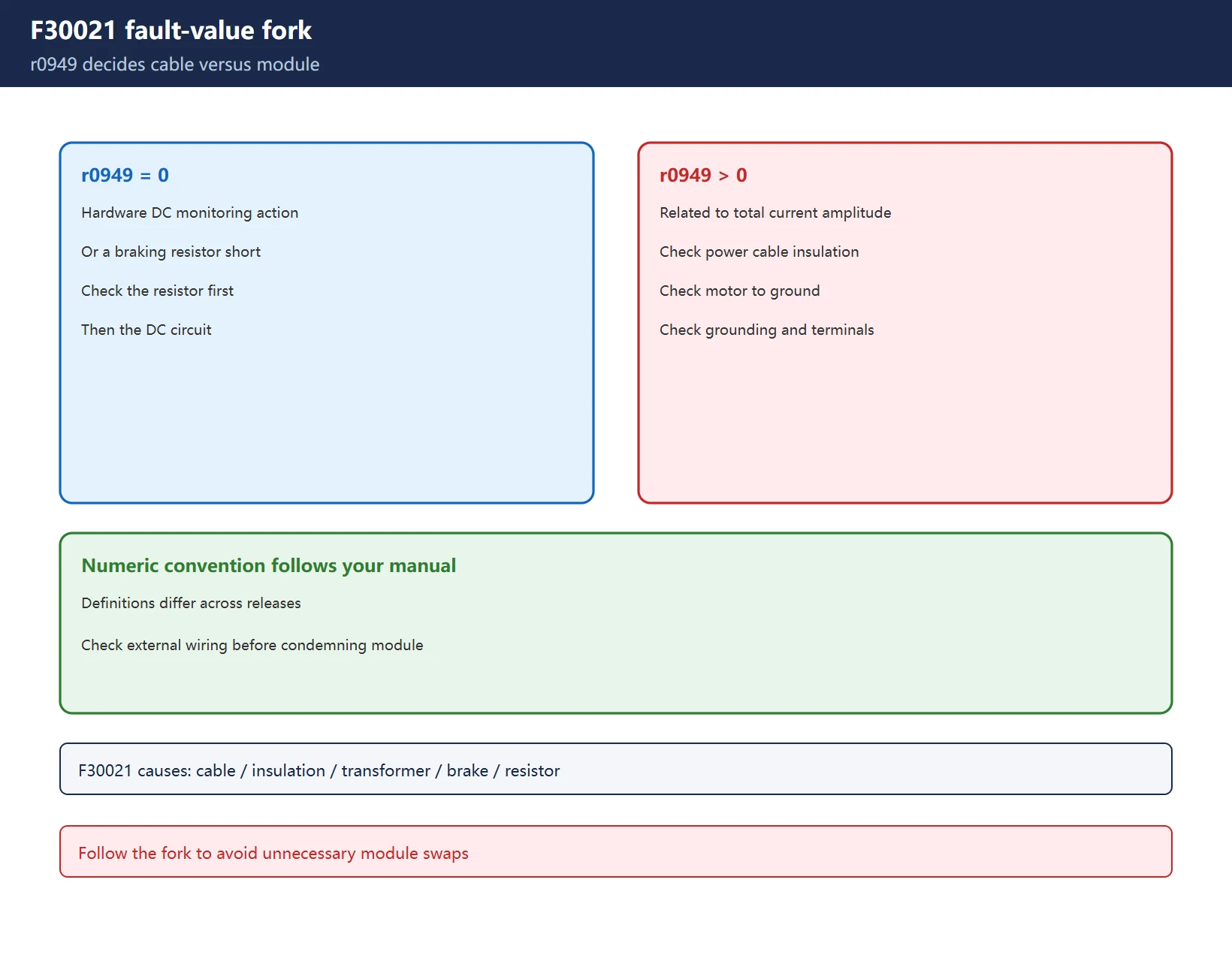
F30021 has several documented causes: power cable to ground / between phases, poor motor insulation, current transformer fault, the brake-closing transient, a braking resistor short. r0949 is the fork in the road:
r0949 = 0: points more to hardware DC monitoring action or a braking resistor short -> check the braking resistor and DC circuit first;r0949 > 0: relates to total current amplitude -> check cable, motor insulation and grounding first.
The exact numeric convention must be checked against the manual for your version – definitions are not identical across releases. Chasing external wiring first, before condemning the power module, avoids a lot of unnecessary swaps.
1.5 F30011 main circuit phase loss: the one most often misread as a bad module
F30011 means check three things: fuses (measure whether one is blown), power cable (phase-to-phase / to ground, connectors), and the line reactor.
High-frequency trap: a leftover star point in a star-delta wiring (a link not removed or removed wrongly) produces exactly the same symptom as a main-circuit phase loss. Confirm the motor connection method before judging the power module bad.
1.6 F07011 motor overtemperature: three paths, fault value tells which
The overtemperature signal can come from three paths: KTY84 / PT1000 sensor, PTC normally-closed contact, and additional overload protection. The fault value distinguishes which one (in some versions 200 = I2t model channel, 400 = additional overload protection trip) – the two actions are completely different: one is a thermal-model parameter and load issue, the other an external protection circuit.
Read the fault value definition for your version before acting; replacing a motor just because it says “motor overtemperature” is the most common waste here.
1.7 A30010 sign-of-life lost: swap the cable and see if the alarm follows
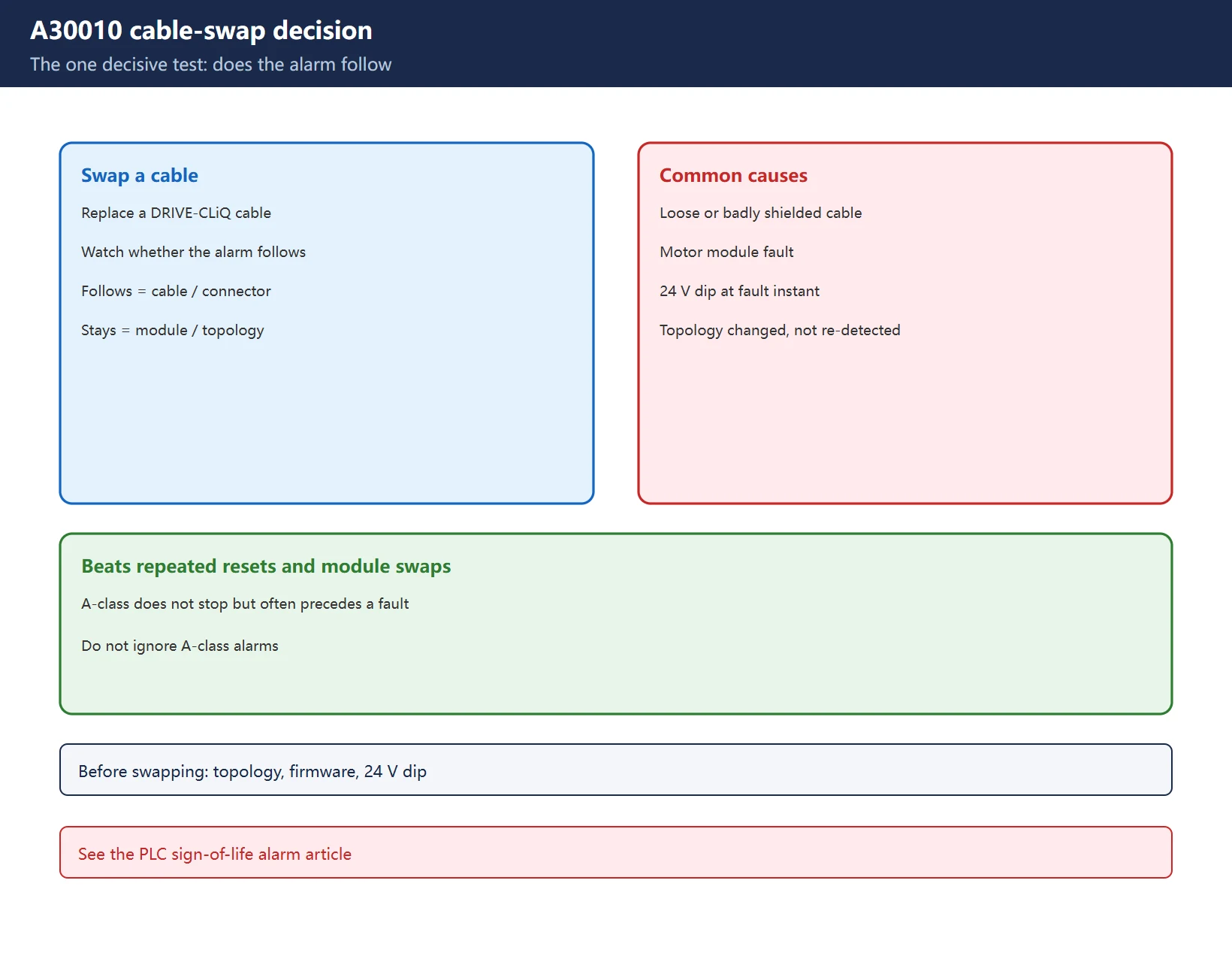
A30010 (sign of life lost) is a communication warning: common causes are a loose or badly shielded DRIVE-CLiQ cable, a motor module fault, a 24 V dip, or a topology change without re-detection.
The one decisive test: swap a cable and see whether the alarm follows – if it follows, it is the cable or connector; if not, it is the module or topology configuration. This beats repeated resets and repeated module swaps. A-class alarms do not stop the machine but often precede a more serious fault – do not ignore them long. See also the 828D sign-of-life alarm for the PLC-side life-sign mechanism.
1.8 F31xxx encoder faults: check cable and topology before swapping
F31100 / F31110 and related encoder / measuring-system faults, entry points in order: encoder cable and connectors -> is the DRIVE-CLiQ topology consistent with installed hardware -> reading head / encoder itself -> did 24 V dip at the fault instant. Encoder faults are easily misread as “the encoder is bad”, yet cable and topology problems are far more common than a failed encoder. Work through these steps before replacing the encoder. Code lists follow the manual for your own version.
1.9 The universal five-step method for any F code
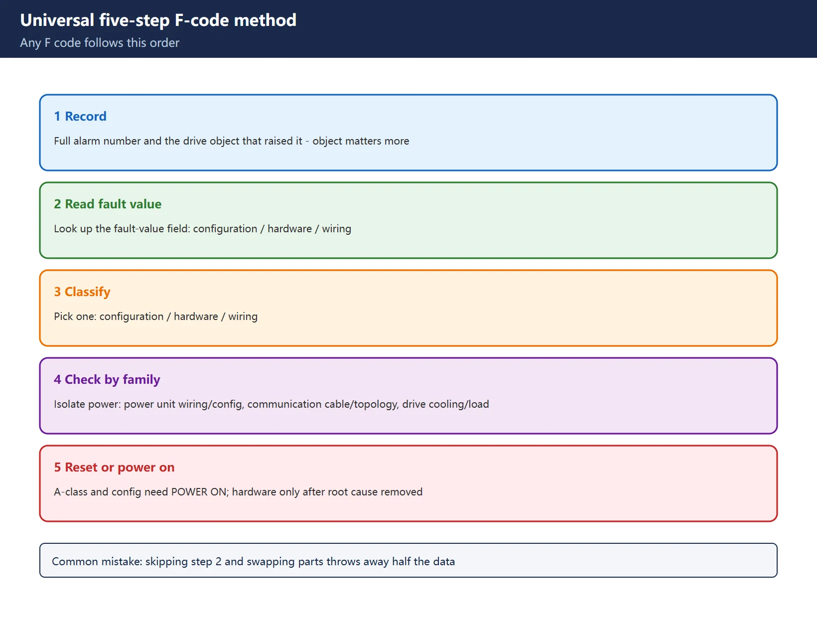
Abstract the cases above into one repeatable flow:
- Record the full alarm number and the fault object: which drive object raised it matters more than the number itself;
- Look up that entry’s fault value field: it decides configuration / hardware / wiring, half the diagnostic information;
- Classify: configuration / hardware / wiring, pick one;
- Isolate power and check by family: power unit -> wiring and configuration; communication -> cable and topology; drive -> cooling and load;
- Reset or POWER ON: A-class and configuration changes need a POWER ON; hardware faults reset only after the root cause is removed.
Table 2. Universal five-step F-code method (do not reorder the steps)
The most common mistake is skipping step 2 and swapping parts – without the fault value you throw away half the diagnostic data.
1.10 Three checks before replacing any module
Before deciding to swap a module, confirm three things: is the DRIVE-CLiQ topology consistent with the installed hardware (a changed topology without re-detection produces a flood of false faults), module firmware version (mismatch causes “configuration not supported” alarms), and did the 24 V dip at the fault instant (a dip triggers a string of seemingly unrelated alarms). Rule these out before swapping – it saves downtime and spare parts.
Frequently Asked Questions
Are the 828D alarm 230020 and SINAMICS F30020 the same fault?
Yes – one fault written two ways: the manual says F30020, the 828D screen shows 230020. But F3xxxx → 230xxx is not a fixed offset; some codes and versions differ. Verify each entry against the manual for your own version.
How do I troubleshoot a F30021 ground fault, and what does fault value r0949 mean?
Read r0949 first: = 0 points more to hardware DC monitoring or a braking resistor short, so check the resistor and DC circuit; > 0 relates to total current amplitude, so check the power cable, motor insulation and grounding. Exact numeric conventions follow the manual for your version.
For F07011 motor overtemperature and F30011 phase loss, what three things do I check first?
For F07011, work out which sensing path tripped (KTY84/PT1000, PTC closed contact, additional overload) and read the fault value; for F30011 check fuses, power cable and line reactor, and rule out a leftover star point in star-delta wiring. On both, do not judge the module bad first.
Last updated: 2026-11-19
Where to go next
- FANUC Troubleshooting — the full guide library: alarms, diagnosis numbers, servo, spindle, PMC and electrical faults, organised by symptom.
- CNC Repair Tools — which instrument measures what: multimeters, clamp meters, insulation testers and oscilloscopes, with the specification that actually matters.
- Remote Technical Support — have the readings reviewed with you: alarm reverse lookup, PMC ladder analysis and servo tuning advice by call. Repair companies and integrators welcome.
- Buying & Ownership Decisions — refurbished vs new, used-machine checks, software licensing and manuals: spend with the field facts in hand.
Read the guide, get the right instrument, or walk the diagnosis through with someone — pick whichever you need.


















暂无评论内容