


Chinese version: PMC scan cycle, missed inputs and early timers; related: what a PMC is and scan time, PMC force output, PMC ladder beginner tutorial, CNC alarm number formats by brand.
11.1 What a scan cycle is: read inputs, execute, write outputs, repeat
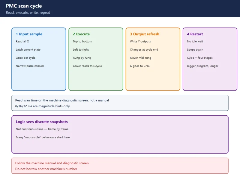
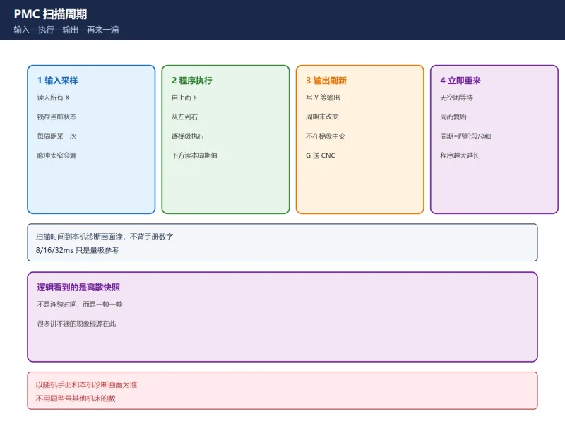
The PMC is the PLC built into every FANUC CNC. It repeats one loop continuously: sample inputs → execute the ladder top-to-bottom → refresh outputs → start again immediately. That loop is the scan cycle; the time for one loop is the scan time.
| Stage | What the PMC does | Field meaning |
|---|---|---|
| Input sampling | Reads all X addresses, latches current state | Sampled once per cycle; changes between samples can be missed |
| Program execution | Runs the ladder top-to-bottom, left-to-right | Lower rungs see values already computed this cycle |
| Output refresh | Writes results to Y and other outputs | Physical outputs change at cycle end, never mid-rung |
| Restart | Immediately begins the next cycle | No idle wait — it starts over |
Table 1: the four stages of one scan
Remember one sentence: your logic does not see continuous time — it sees a sequence of discrete snapshots. Many “impossible” behaviours trace back to this.
11.2 How long is the scan time: read it from the control, not a manual
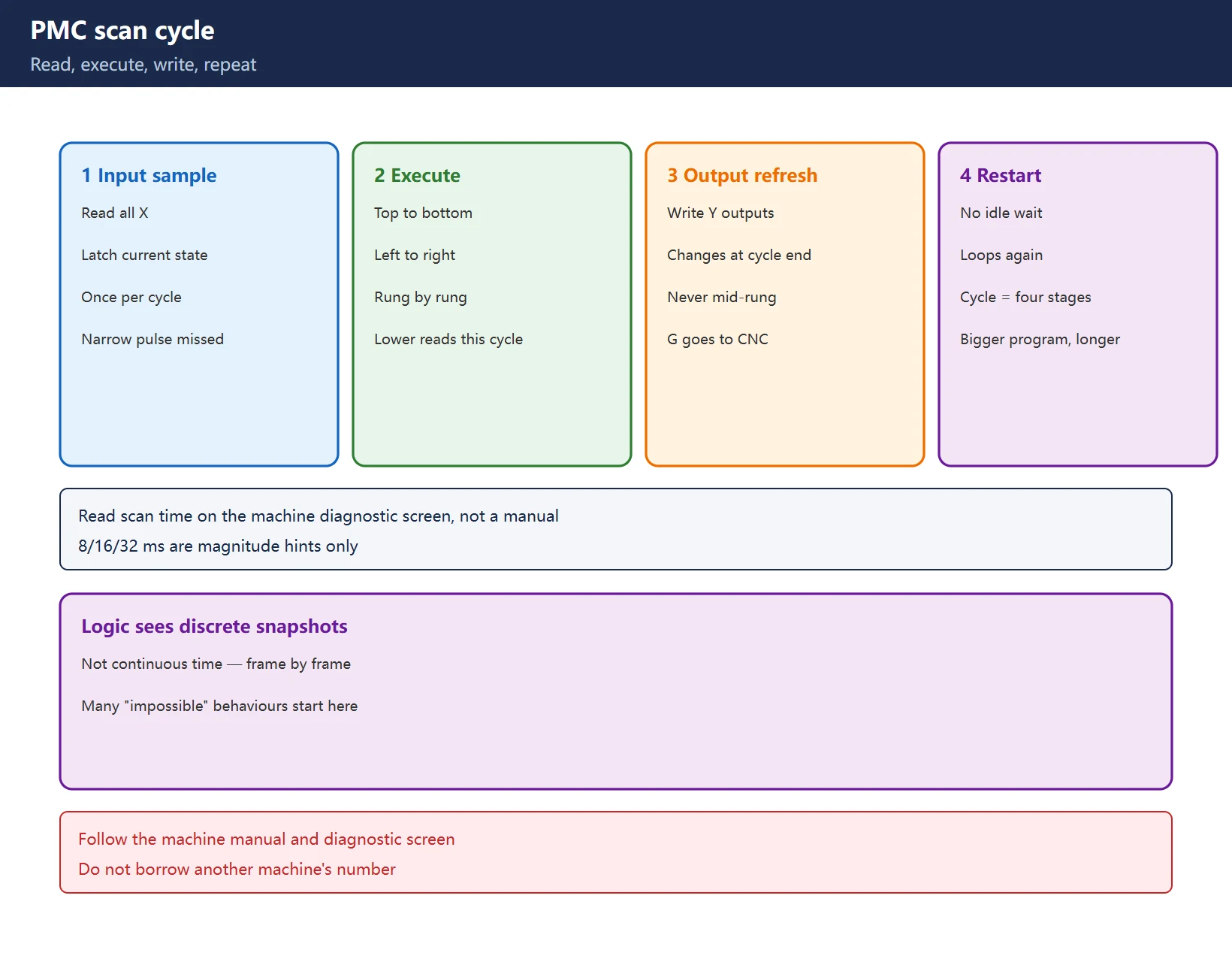
The common question is “what is the PMC scan time?” The right answer is not to quote a number — it is to read it on the machine’s diagnostic screen. On most FANUC systems the PMC or system diagnostic screen shows PMC execution time alongside ladder status. Record it as this machine’s baseline.
- Scan time varies with program length and instruction complexity — bigger programs and heavier instructions mean longer cycles;
- Different PMC models have different baselines. The “8 / 16 / 32 ms” figures circulating online are typical order-of-magnitude references only, not this machine’s measured value;
- For a timing question, use the value you read on this machine, not one from another machine of the same model.
This site gives method and magnitude only — the specific value follows the machine’s own manual and diagnostic screen. That is the standing rule against inventing parameters and numbers.
11.3 Four typical symptoms: translate “random” into scan-cycle language
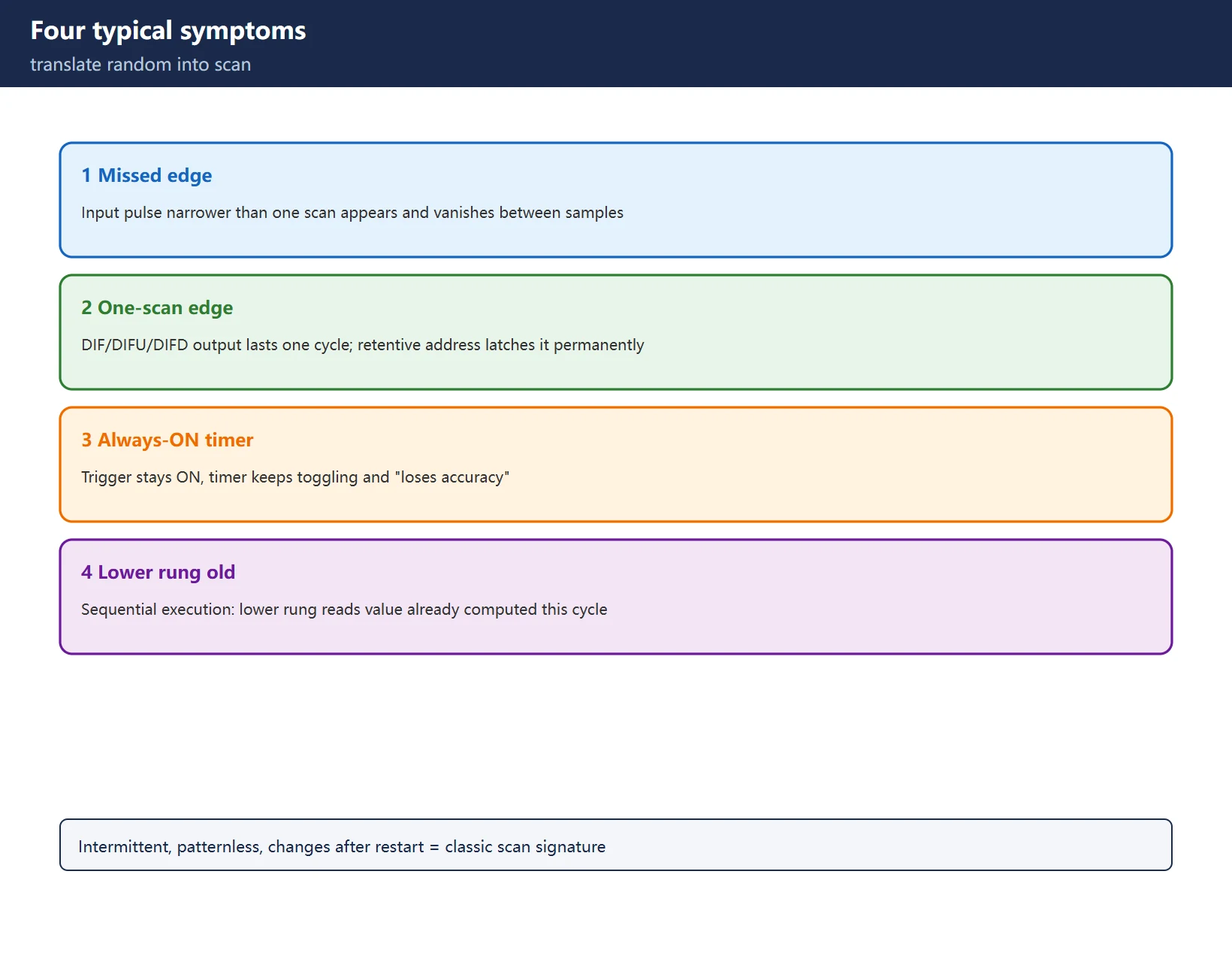
Symptom one — a missed edge input. A short input pulse narrower than one scan can appear and disappear between two samples; the PMC never sees it. The fix is to widen the signal (move the cam or sensor) or use an input with a latching function — not to blame the ladder.
Symptom two — a DIF edge output lasts one scan. DIF / DIFU / DIFD edge outputs are valid for exactly one scan cycle. That is correct behaviour, not a fault. Wire such an output into a retentive address (R) and the one-scan pulse is latched into a permanent signal, losing all meaning.
Symptom three — a constantly ON trigger breaks a timer. If the trigger condition stays ON, the timer keeps satisfying or un-satisfying its condition and “loses accuracy.” A timer needs a stable condition with a clear edge.
Symptom four — a lower rung reads last scan’s value. The sequential program executes strictly top-to-bottom. A rung written below a timer or coil reads the value already computed this cycle. If you need the “just written” value, mind the rung order.
11.4 Address layers against the scan: when X/Y/F/G change
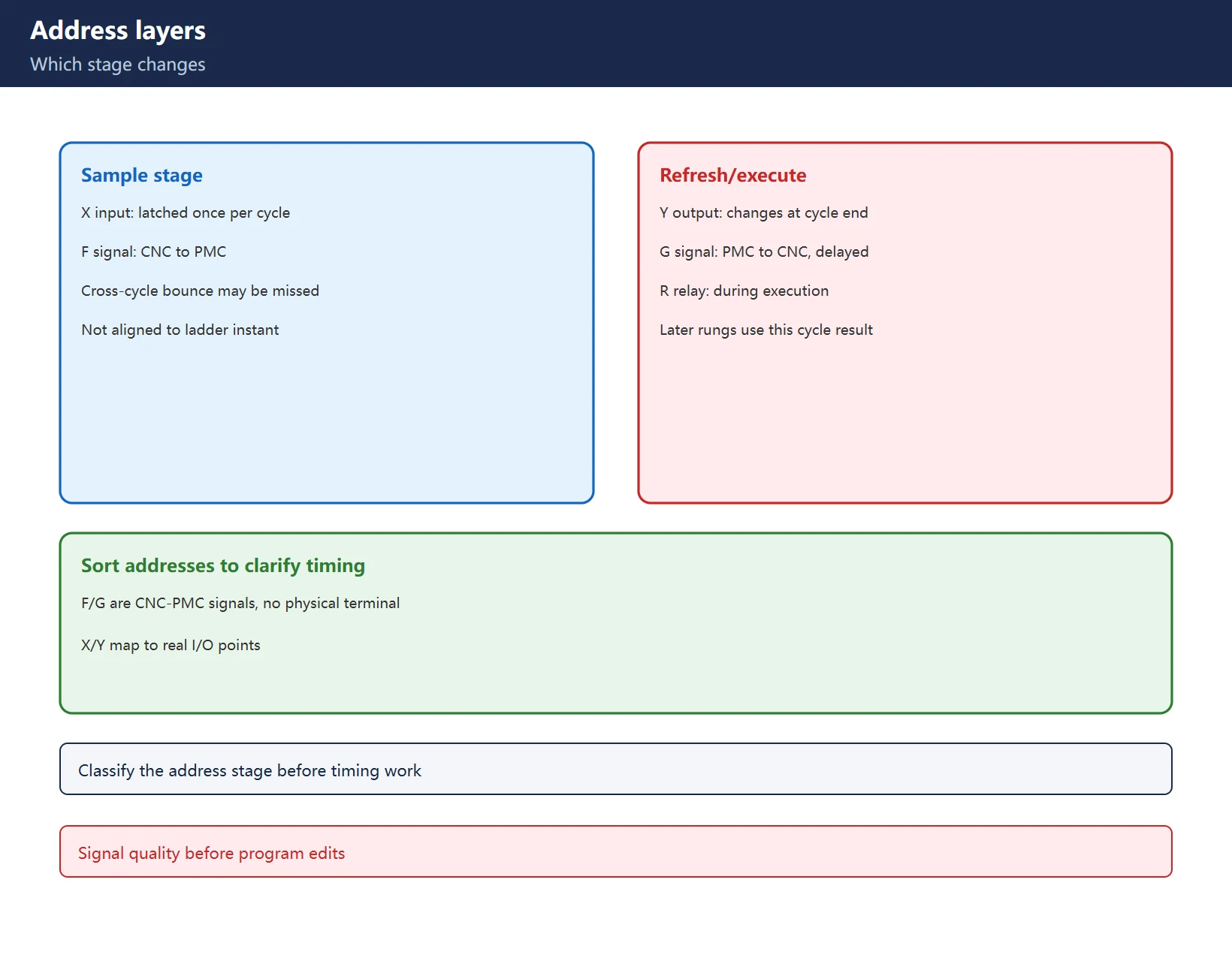
Sorting addresses by scan stage makes timing troubleshooting much clearer:
| Address | Changes at stage | Scan-cycle limitation |
|---|---|---|
| X (input) | Input sampling | Latched once per cycle; bounce across a cycle boundary may be missed |
| Y (output) | Output refresh | Physical output changes at cycle end, never mid-rung |
| F (CNC to PMC) | Input sampling | CNC signal and ladder logic are never aligned to one instant |
| G (PMC to CNC) | Output refresh | The CNC reads the refreshed value, with a delay |
| R (internal relay) | Program execution | This cycle's result is used immediately by later rungs |
Table 2: address groups vs scan stages
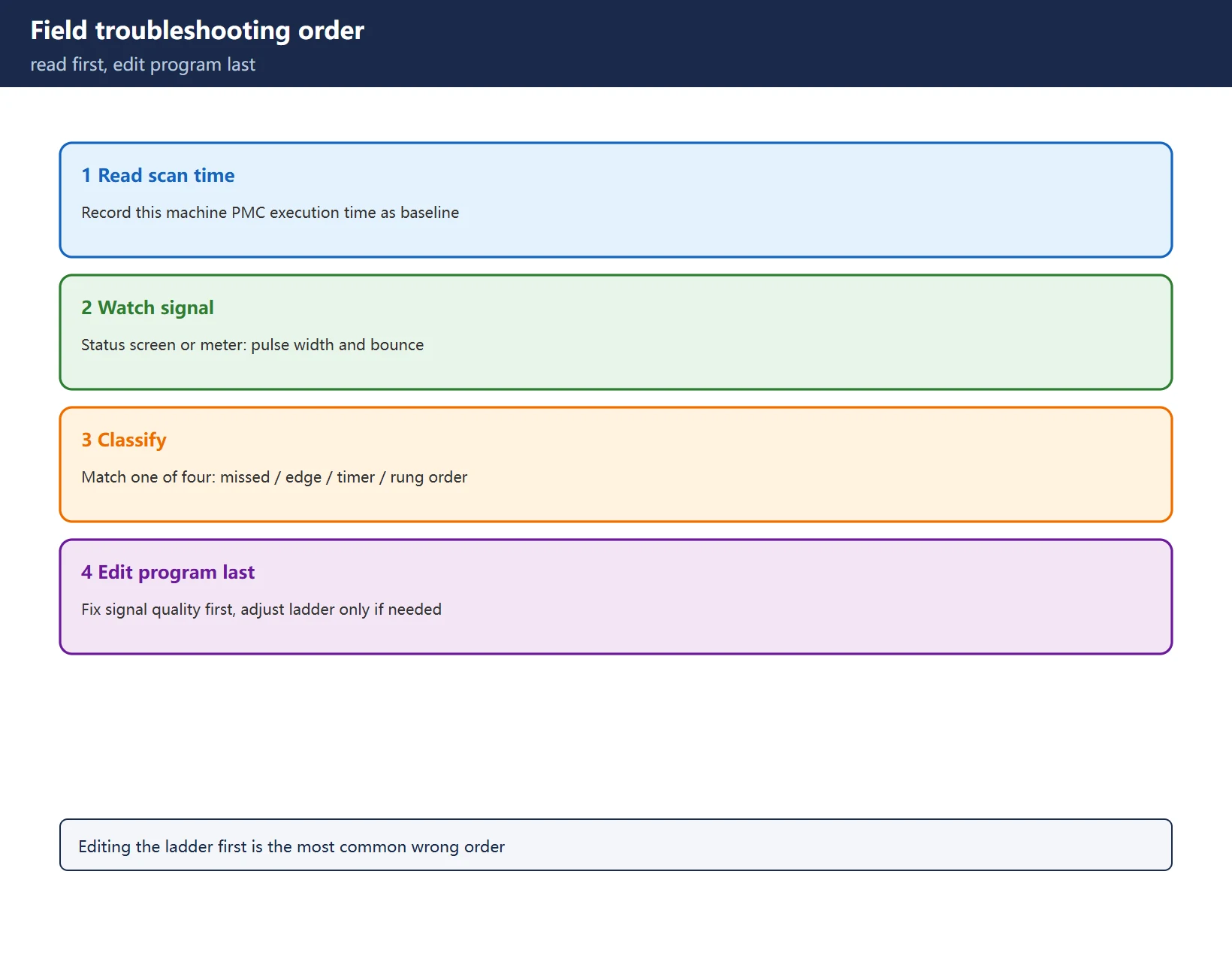
11.5 Field order: read the cycle, watch the signal, change the program last
For a suspected timing problem, work in this order to avoid wasted edits:
- Read the scan time: record this machine’s PMC execution time on the diagnostic screen as a baseline;
- Watch the signal: use the signal status screen or a meter to confirm input pulse width and any bounce;
- Classify the symptom: match against the four in section 11.3 — missed input, edge, timer, or rung order;
- Change the program last: fix signal quality first (widen the pulse, remove bounce); only then adjust the ladder if truly needed.
Editing the ladder first is the most common wrong order. Scan-cycle problems rarely get fixed by program edits — the cause is not wrong logic but a mismatch between signal and sampling timing.
Frequently Asked Questions
Is a shorter PMC scan time always better?
It is not a freely adjustable “smaller-is-better” parameter — it is set mainly by program size and PMC model. The field goal is to make critical signals much wider than the scan cycle, not to “tune down” the cycle.
Why does wiring an edge output to a retentive relay fail?
Because the edge output is valid for only one scan; once latched into a retentive address it becomes permanently ON and loses the meaning of “edge.” To trigger an action from an edge, use a set/reset or a counter input.
How do I confirm an intermittent fault is a scan-cycle issue?
Read the machine’s scan time, then measure the suspect signal’s pulse width. If the width approaches or falls below one scan cycle, that is essentially confirmation. Intermittent, patternless behaviour that changes after a restart is the classic signature.
Last updated: 2026-11-17
Where to go next
- FANUC Troubleshooting — the full guide library: alarms, diagnosis numbers, servo, spindle, PMC and electrical faults, organised by symptom.
- CNC Repair Tools — which instrument measures what: multimeters, clamp meters, insulation testers and oscilloscopes, with the specification that actually matters.
- Remote Technical Support — have the readings reviewed with you: alarm reverse lookup, PMC ladder analysis and servo tuning advice by call. Repair companies and integrators welcome.
- Buying & Ownership Decisions — refurbished vs new, used-machine checks, software licensing and manuals: spend with the field facts in hand.
Read the guide, get the right instrument, or walk the diagnosis through with someone — pick whichever you need.
The original Chinese version — same procedure, with the full field notes.


















暂无评论内容