


Chinese version: Schematic, I/O table and PMC ladder cross-reference; related: reading a CNC electrical schematic, PMC data table, counter, timer and keep relay quick reference, external alarm four-step reverse lookup, FANUC PMC force output.
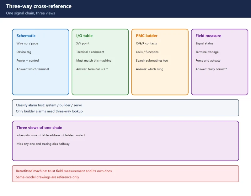
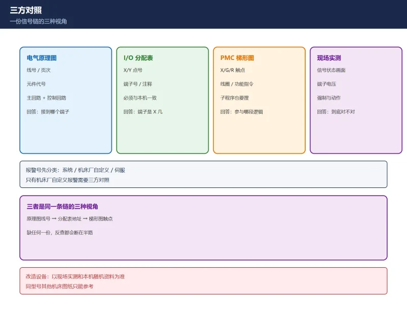
10.1 Each document owns one link — none does the whole job
| Document | Question it answers | Key fields | Most common trap |
|---|---|---|---|
| Electrical schematic | Where current flows, which terminal a device uses | Wire number, page, device tag | Reading only the power circuit, missing the control circuit |
| I/O allocation table | Which PMC address a terminal maps to | X/Y point, terminal number, comment | Stale table after a field rewiring |
| PMC ladder | What logic this address takes part in | X/G/R contacts, coils, function instructions | No contact found, assumed the address is bad |
Table 1: responsibility boundary of the three documents
The three are one signal chain seen from three angles: schematic wire number → table address → ladder contact. Reverse tracing is simply taking one known value and calculating the other two.
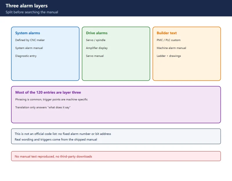
10.2 Alarm text first: decide system alarm or machine-builder alarm
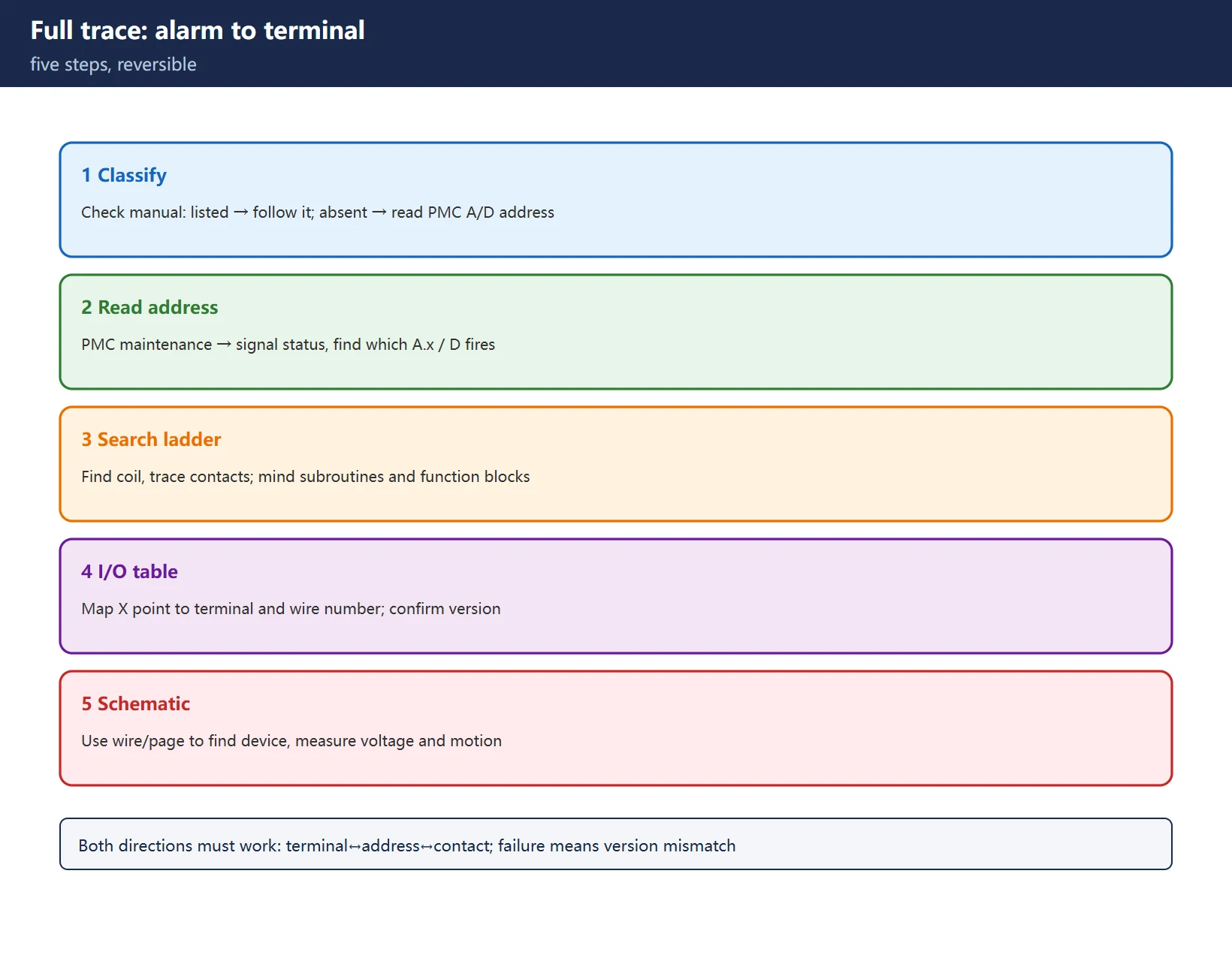
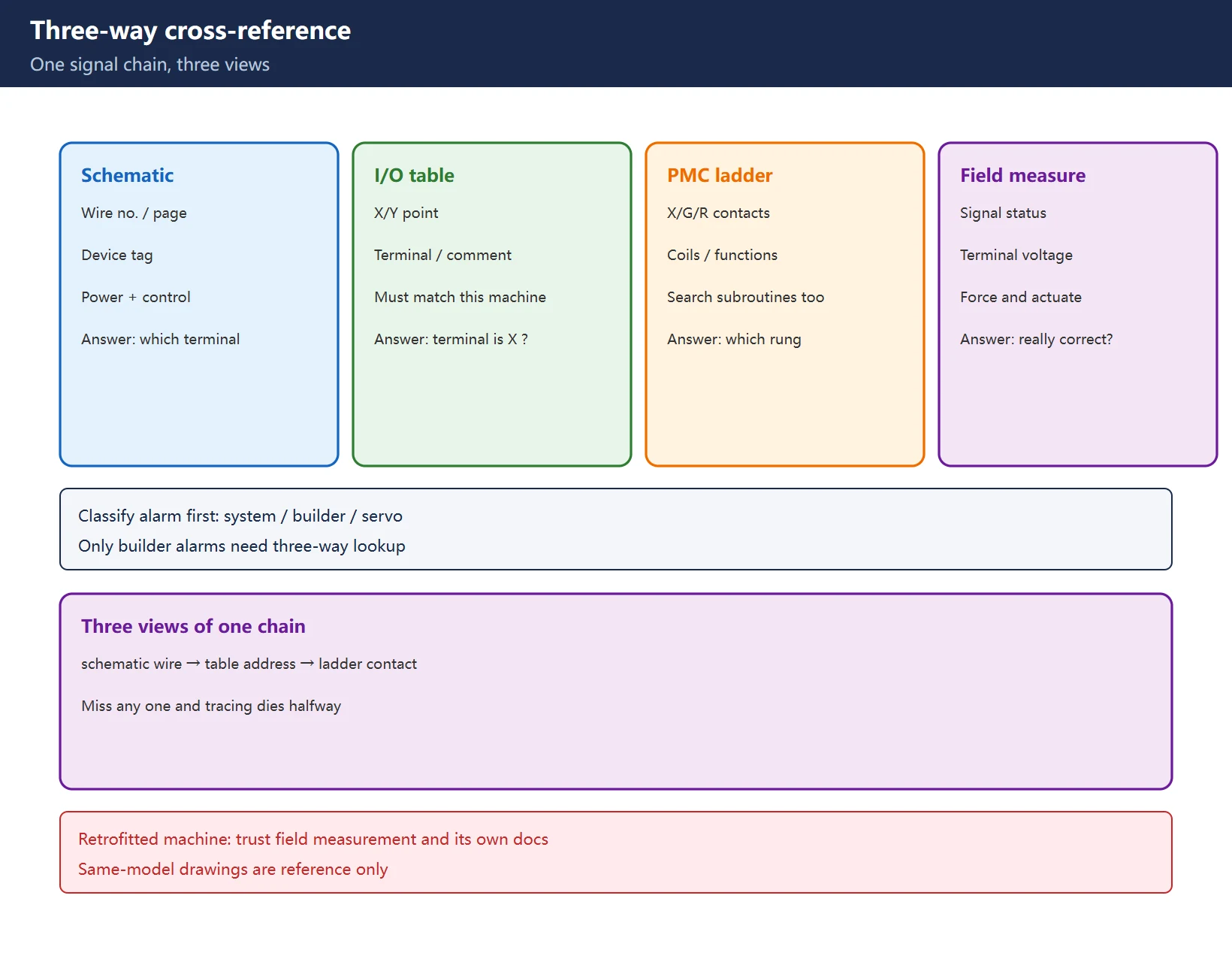
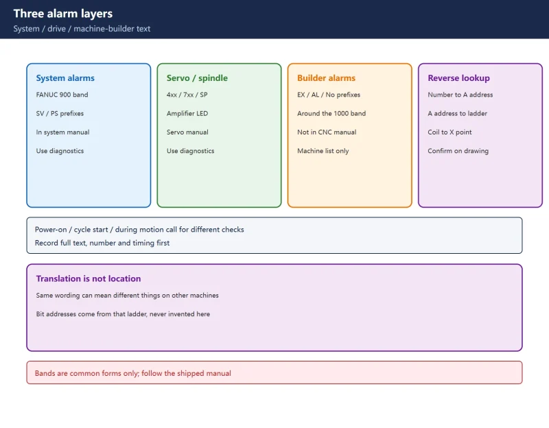
The first step is never opening the ladder. It is classifying the alarm:
- System alarm (in the FANUC manual): the number has an official meaning — consult the manual before touching addresses;
- Machine-builder custom alarm (not in the manual): reverse from a PMC A/D address to an ALARM / DISPB instruction in the ladder;
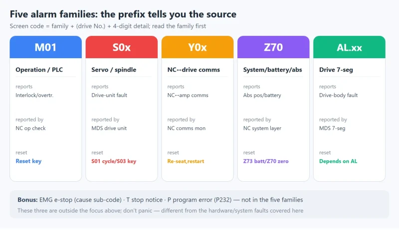
- Servo / spindle alarm: follows the SV/SP bands, unrelated to the PMC ladder — do not waste time on addresses.
Only the second class needs a three-way lookup. The test is simple: look the number up in the manual. If it is there, follow the manual; if not, go to the PMC maintenance screen and read the A or D address. Get this step wrong and everything after it is wasted effort.
10.3 Address to terminal: using the I/O table without breaking the chain
Once you have the X point, most people search the ladder immediately — that is correct; but to reach the physical terminal you must return to the I/O table:
- Find the terminal number for this X point (normally marked on the I/O module or terminal strip);
- Use the terminal and wire number to locate the page and wire in the schematic;
- Follow the wire to the actual device — limit switch, proximity sensor, pressure relay, or pushbutton contact.
The reverse works too: start from a device on the drawing, trace wire number → terminal number → X point → ladder contact. You must be able to walk both directions; if one fails, the documents have a version mismatch.
Critical reminder: the table and drawings must match this specific machine. Retrofitted machines commonly have “factory drawings, rewired field” — when that happens, trust field measurement and the machine’s own documentation, not another machine of the same model.
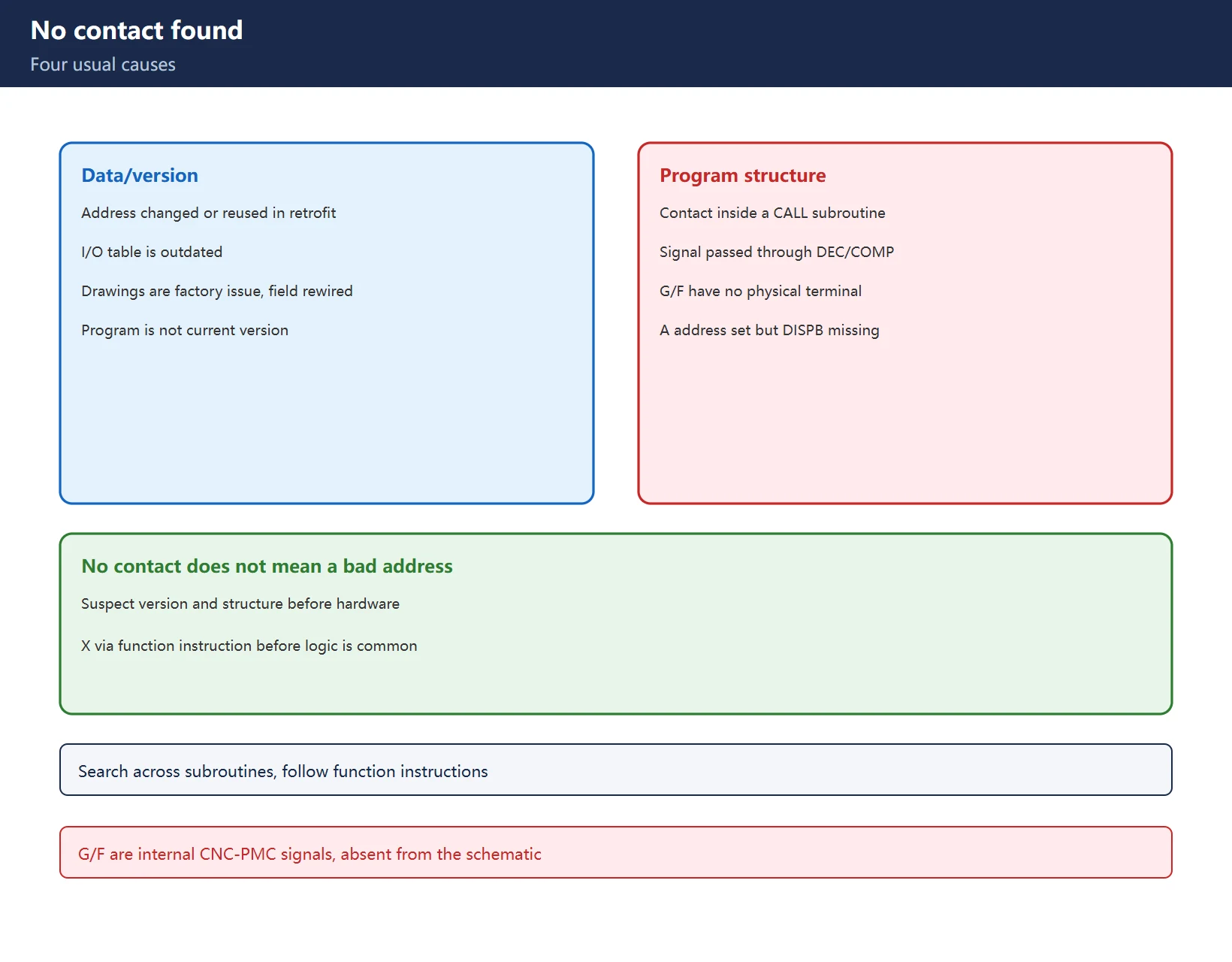
10.4 No contact in the ladder: four usual causes
When the chain breaks at the ladder stage, check in this order:
- Address reused or changed: one X point used by several circuits, or the address changed in a retrofit — confirm the current program version;
- Contact inside a subroutine: not in the main program — search inside CALL-invoked subroutines;
- Signal passed through a function instruction: the X point goes through DEC/COMP before the logic — searching X directly misses it;
- It is a signal, not a terminal: G/F are CNC-to-PMC signals with no physical terminal — do not hunt for a wire on the drawing.
10.5 Field verification: the last step is always forcing and measurement
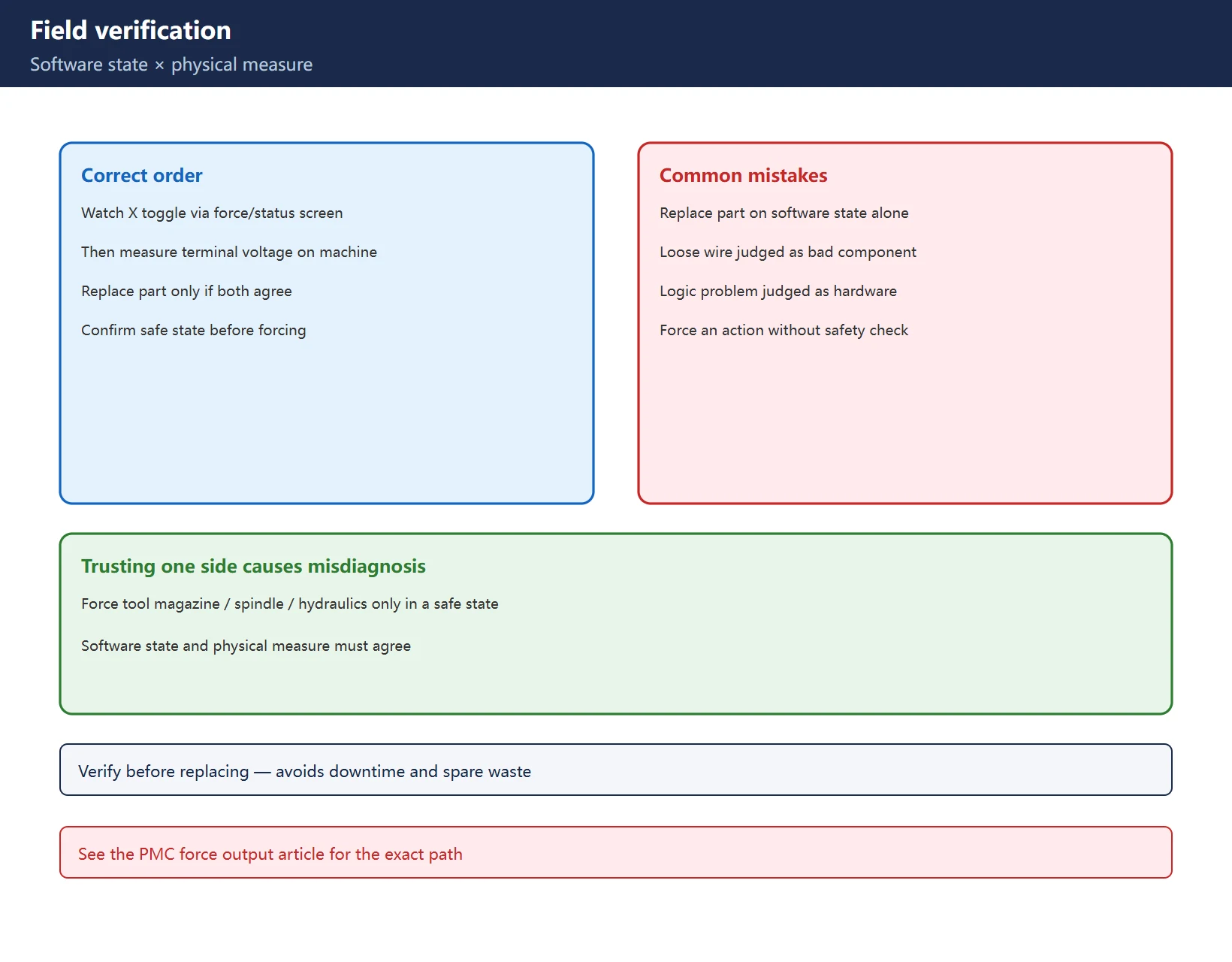
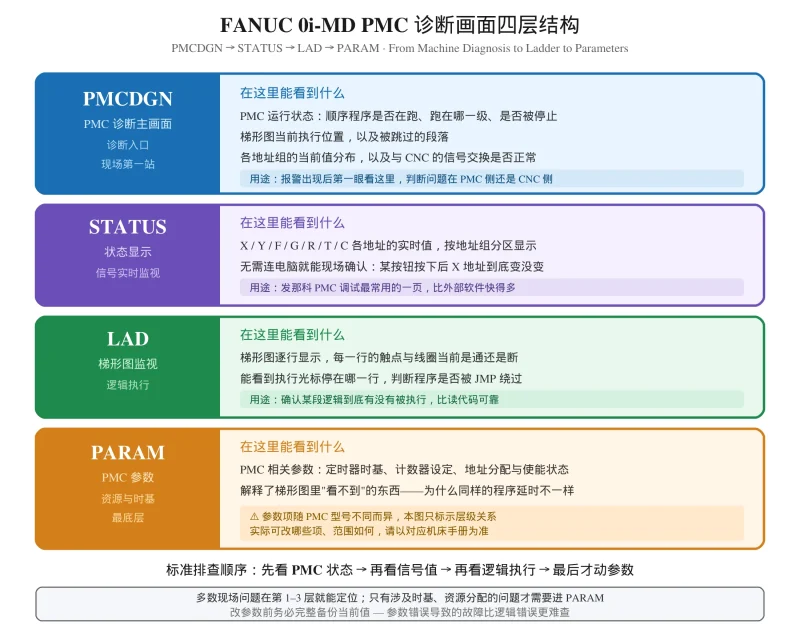
Once you have a suspect device, do not replace it yet. Use PMC force output or the signal status screen to watch whether this X point really toggles during the action, then measure the terminal voltage on the machine. Software state and physical measurement must agree at the same time before you can lock onto the fault. Trusting only one side easily misdiagnoses a loose wire as a bad component, or a logic problem as hardware failure.
Before forcing, confirm the safety preconditions — tool magazine, spindle, or hydraulic actions may execute the instant you force. Work in a safe state. For the exact path, see how to use PMC force output.
Frequently Asked Questions
Does a three-way lookup have to start from the alarm?
No. Any known value works as a start: terminal to address, address to drawing, contact to device. The rule is to first identify which link you are standing on, then decide which direction to calculate.
If the drawing and the I/O table disagree, which wins?
Field measurement first, then the machine’s own documentation that matches the current machine. Drawings from another machine of the same model are reference only — never copy them onto a retrofitted machine.
Can a G/F address be found as a terminal on the schematic?
No. G/F are internal signals between the CNC and the PMC with no separate physical terminal. To reach a physical terminal, work from an X/Y address.
Last updated: 2026-11-17
Where to go next
- FANUC Troubleshooting — the full guide library: alarms, diagnosis numbers, servo, spindle, PMC and electrical faults, organised by symptom.
- CNC Repair Tools — which instrument measures what: multimeters, clamp meters, insulation testers and oscilloscopes, with the specification that actually matters.
- Remote Technical Support — have the readings reviewed with you: alarm reverse lookup, PMC ladder analysis and servo tuning advice by call. Repair companies and integrators welcome.
- Buying & Ownership Decisions — refurbished vs new, used-machine checks, software licensing and manuals: spend with the field facts in hand.
Read the guide, get the right instrument, or walk the diagnosis through with someone — pick whichever you need.
The original Chinese version — same procedure, with the full field notes.























暂无评论内容