


Sister article: FANUC full to semi closed-loop scale bypass – the Chinese guide; related: FANUC SV0381/0384/0385 linear scale alarm family, Fanuc backlash compensation 1851, Fanuc pitch error compensation 3620-3624, SINUMERIK 828D semi-closed loop conversion, Fanuc servo amplifier replacement.
16.1 Know the cost first
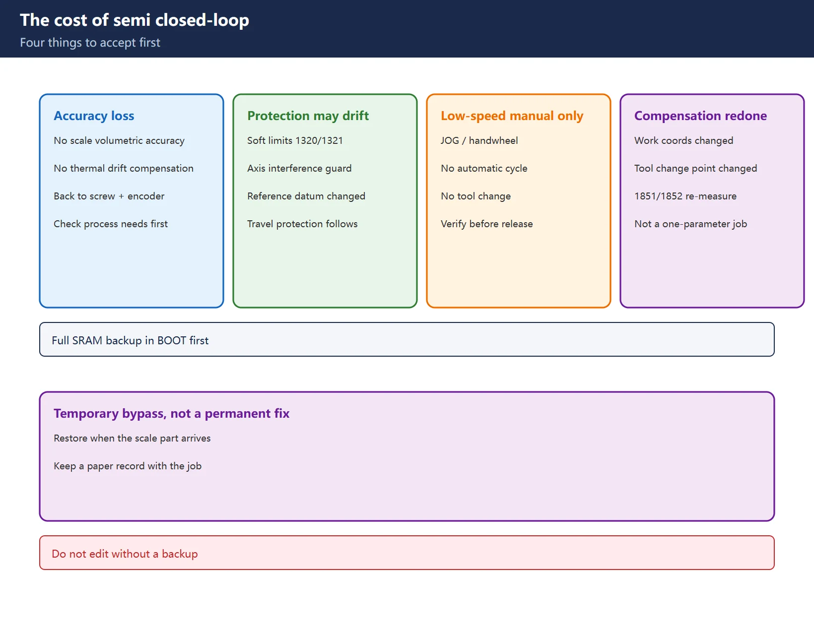
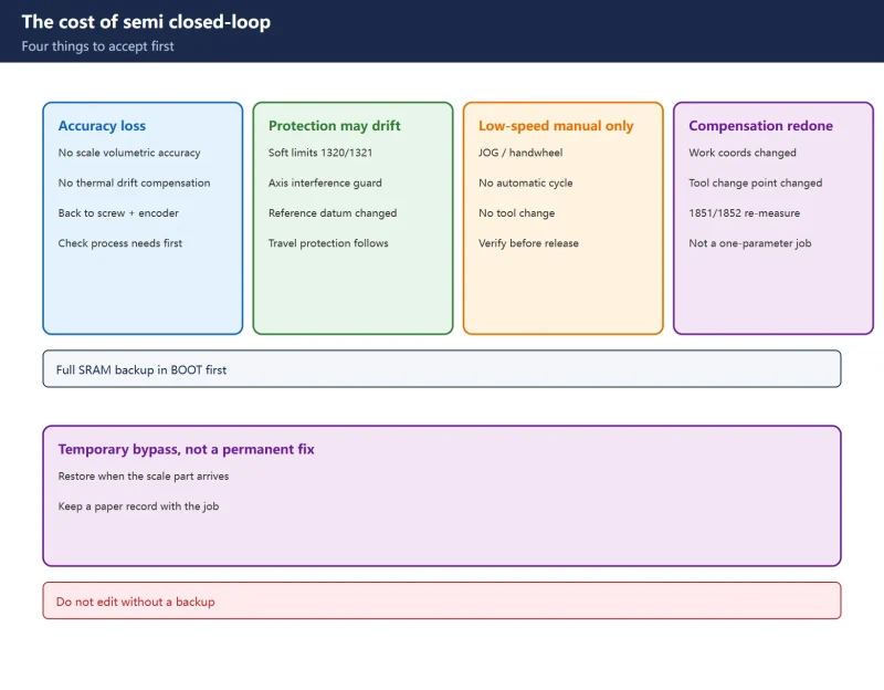
- You lose the volumetric accuracy and thermal-drift compensation the scale provided – positioning falls back to the screw and motor encoder.
- Software limits (1320/1321) and axis interference protection may no longer be reliable: the reference datum moved, so travel protection follows a different basis.
- JOG / handwheel movement only at low speed: no automatic cycle, no tool change until the three verification steps pass.
- Work coordinates, tool-change position and backlash compensation all need redoing – this is not a one-parameter job.
16.2 When to switch, and when not to
Switch for a contaminated scale, failed read head, broken cable or intermittent scale pulses – bypass first to protect production, restore when parts arrive.
Do not switch when you want to judge mechanical accuracy or drivetrain health: measure backlash in semi closed-loop on purpose. That counter-intuitive step removes the scale error from the measuring chain, so what you read is closer to the screw and coupling themselves. See the 1851 backlash measurement procedure.
16.3 Parameter cross-reference table (core; verify every item against your manual)
Table 1. Cross-reference (example values are illustrative; check every ⚠️ item against your manual)
16.4 Three disputed points – do not copy any single source
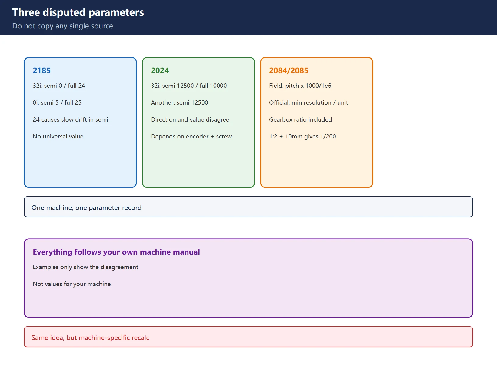
- 2185: a 32i case gives “semi 0 / full 24” and notes that 2185=24 causes slow drifting in semi mode while 0 stops it; another 0i source gives “semi 5 / full 25”. There is no universal 2185 value – follow your manual.
- 2024: the same 32i case gives “semi 12500 / full 10000”, while another gives semi 12500 – both direction and value disagree, because 2024 depends on encoder resolution and screw pitch.
- 2084/2085: a common field formula is “screw pitch (mm) x 1000 / 1000000, reduced to a fraction”, while official material states “detector minimum resolution / detection unit”; with a gearbox the ratio is included (e.g. 1:2 reduction, 10 mm screw -> N/M = 1/200). The two are essentially the same idea, but you must recalculate from your own screw and gearbox.
Table 2. Disputed points (use your machine’s manual, never another machine’s numbers)
16.5 Four preparations before editing
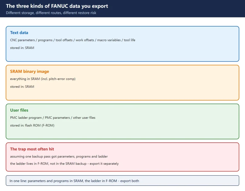
- Take a full SRAM backup in the BOOT screen (parameters + ladder + pitch-comp table) – the only insurance for returning to full closed-loop.
- Record the current full-loop reference coordinate (fixture gauge or indicator reading) as a comparison afterwards.
- Emergency stop in place, power off: follow your manual when changing servo parameters, especially FSSB channel parameters.
- Mid-stroke, tool removed, reduced override: park axes mid-travel to avoid a crash on unexpected motion.
16.6 Three verification steps after the change
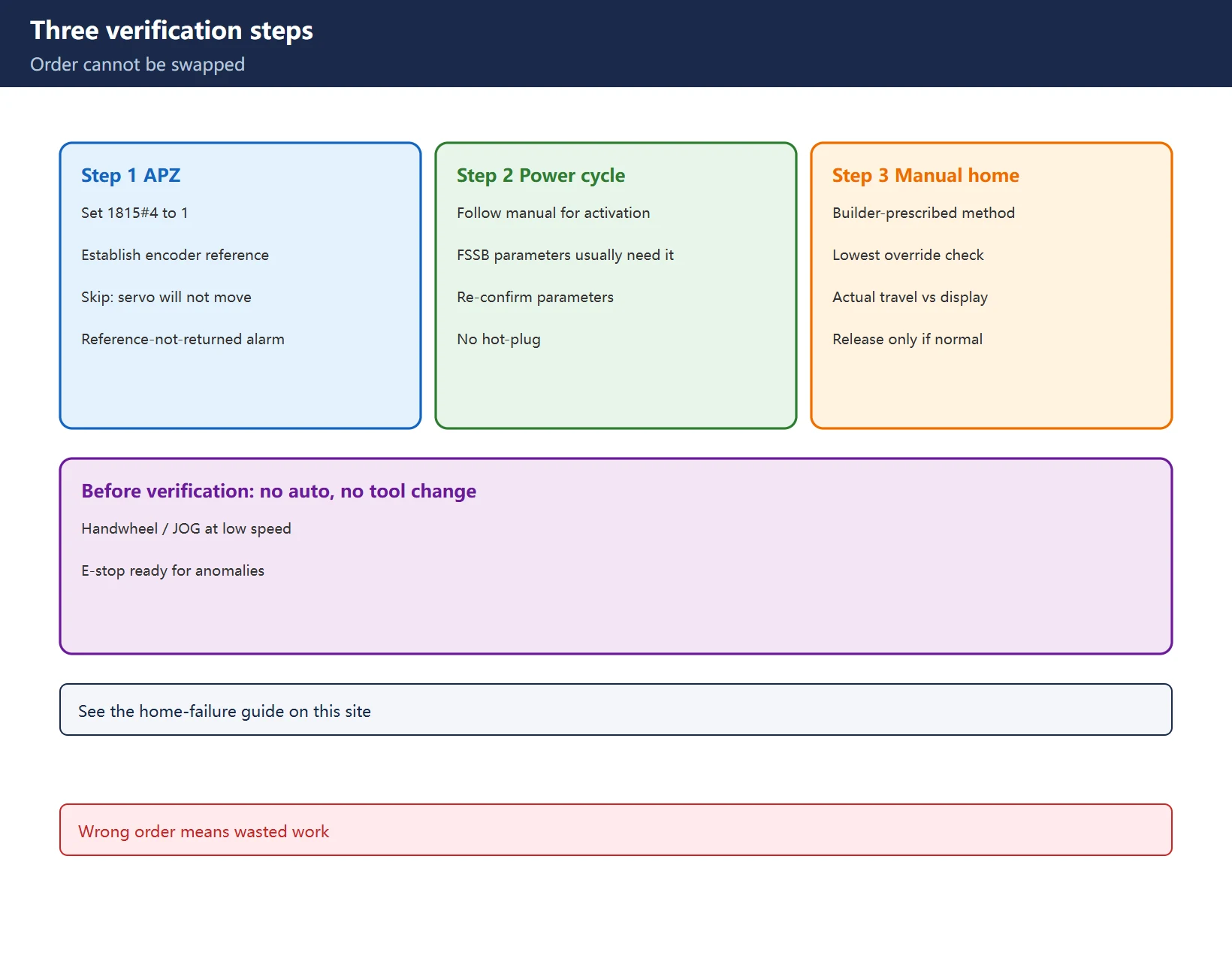
- Set 1815#4 (APZ) to 1 to establish the encoder reference point – skip this and the servo will not move, with a “reference point not returned” alarm. The Chinese guide on this site covers the full 1815#4 APZ and manual reference-return procedure.
- Power-cycle (check your manual for which parameters need it; FSSB parameters usually do).
- Return to reference point manually as the builder prescribes, then check actual travel against the coordinate display at the lowest override using handwheel or JOG.
Table 3. The three verification steps, in order
16.7 Three things to re-check after switching
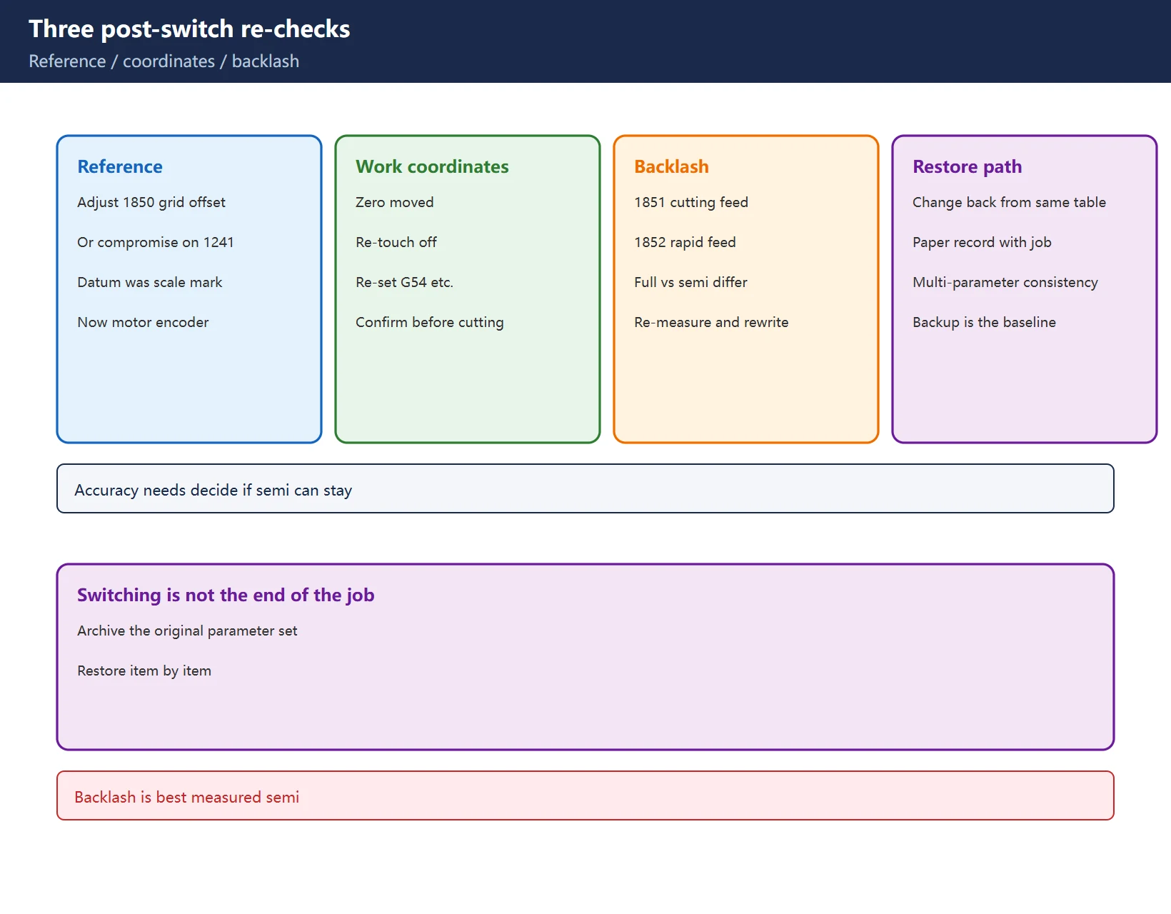
- Reference point position: adjust 1850, or as a compromise change the 1241 tool-change position offset; re-set the work coordinate system for machining.
- Workpiece coordinate system: the zero moved, so re-touch off and re-set G54 and friends.
- Backlash compensation: re-measure and rewrite 1851/1852 – backlash is not the same in full and semi closed-loop.
16.8 Restoring full closed-loop
Change every item back strictly from the same table and keep a paper record with the job. Consistency across many parameters matters more than any single value – the saved parameter set is your restoration baseline.
16.9 Rotary axes (A/B) are different
1815#6 (built-in absolute detector), 1821 positioning counter capacity and 2275#0 RCN (1/8-revolution datum) put rotary axes in a different parameter family from linear axes – do not copy the linear-axis procedure. The Chinese guide on this site covers fourth-axis FSSB definition, servo initialization and reference return.
16.10 Axis not enabled after the switch
If the axis will not move, check the G130.x axis-enable signals and K30.0 hold relay – confirm against the actual ladder in your machine, never copy someone else’s addresses.
16.11 Temporary handling of soft limits
1320/1321 can be widened temporarily to allow motion, but warning: this removes travel protection – watch the mechanical position during manual moves and keep a hand on the emergency stop.
16.12 Sources and compliance
This is a method write-up. Parameter numbers come from the general FANUC servo/connection manual framework and public field cases; no manual text is reproduced and no manual PDF is provided. Example values (2024=12500, 2185=0/24, etc.) illustrate the disagreement only – they are not values for your machine; use your own machine’s manual.
Frequently Asked Questions
How do I temporarily bypass a FANUC linear scale and switch to semi closed-loop? Which parameters change?
The main switch is 1815#1 from 1 to 0 (no separate detector). Then recalculate 2024, 2084/2085 and 1821 for semi mode and handle 1815#5, 2003#5, 2019#7 and 2185 as the machine requires. Take a full SRAM backup first, then do the APZ / power-cycle / manual reference-return verification. 2185 and 2024 have no universal values – use your manual.
After switching to semi closed-loop the servo will not move or reports a reference-point error. Why?
Most often 1815#4 (APZ) was not set to establish the encoder reference point. It can also be 1815#5 left unchanged causing DS0300 / DS0306, or FSSB parameters not yet applied after a power cycle. Complete the APZ -> power-cycle -> manual reference-return sequence.
After the switch the part dimensions changed or the tool changer crashed. Why?
The reference datum moved from the scale mark to the motor encoder, so the reference position and work coordinate system both changed. Re-adjust 1850 (or the 1241 tool-change offset as a compromise), re-touch off and re-set the work coordinate system, and re-measure/rewrite 1851/1852 backlash. No automatic cycle or tool change until verification passes.
Last updated: 2026-11-19
Where to go next
- FANUC Troubleshooting — the full guide library: alarms, diagnosis numbers, servo, spindle, PMC and electrical faults, organised by symptom.
- CNC Repair Tools — which instrument measures what: multimeters, clamp meters, insulation testers and oscilloscopes, with the specification that actually matters.
- Remote Technical Support — have the readings reviewed with you: alarm reverse lookup, PMC ladder analysis and servo tuning advice by call. Repair companies and integrators welcome.
- Buying & Ownership Decisions — refurbished vs new, used-machine checks, software licensing and manuals: spend with the field facts in hand.
Read the guide, get the right instrument, or walk the diagnosis through with someone — pick whichever you need.
The original Chinese version — same procedure, with the full field notes.





















暂无评论内容