


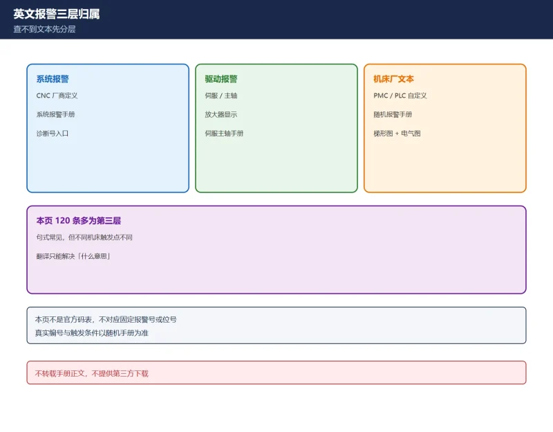
🚨 Scope and compliance: The 900-range alarm meanings here are checked against Fanuc 0i-C Maintenance Manual B-64115EN/02 (Ch. 8 Troubleshooting) and public 0-series / 16i–21i alarm tables. The swap order and board numbers come from maintenance data and manual appendices; the trailing digit/asterisk of A16B/A20B board numbers varies by machine and production batch — always match against the physical board silkscreen and your own manual cover. On battery limits, “10 min for 0i-B” is quoted from the 0i-B connection manual A02B-1000-0940; “30 min for 0i-C” appears only in third-party citations of the 0i-C manual and was not verified against an official PDF, so it is marked unconfirmed. No manual text is reproduced and no download links are given — only search methods and a decision framework.
30-Second Triage: Three Things First
| Step | Action | Why |
|---|---|---|
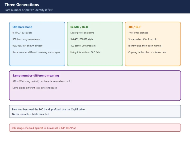
| 1 | Check bare number vs letter prefix | Bare = 0i-A/B/C, 16i/18i/21i, old 0-series; SV/PS = 0i-D/F, 30i generation |
| 2 | Power cycle and see if it returns | One-off is usually noise / poor contact; repeat-on-power-up points to RAM, CPU, boards |
| 3 | Back up SRAM before swapping anything | Swapping boards without a backup turns a recoverable fault into a permanent one |
Table 0 Three-step field triage for legacy alarms
Companion page: Fanuc Alarm, Parameter and Diagnostic Cross-Reference Table. Related on this site: Fanuc 900/950/971 system alarms (0i-MD / newer generation), 0i-Mate / 0i-D same-number-different-meaning, Fanuc data backup and BOOT SRAM backup.
1. Three Generations: Identify Your Control First
| Generation | Alarm format | Range signature |
|---|---|---|
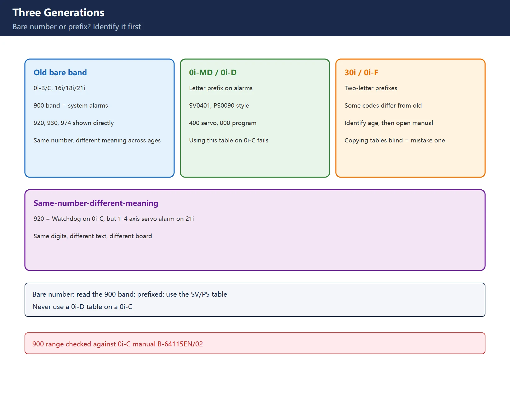
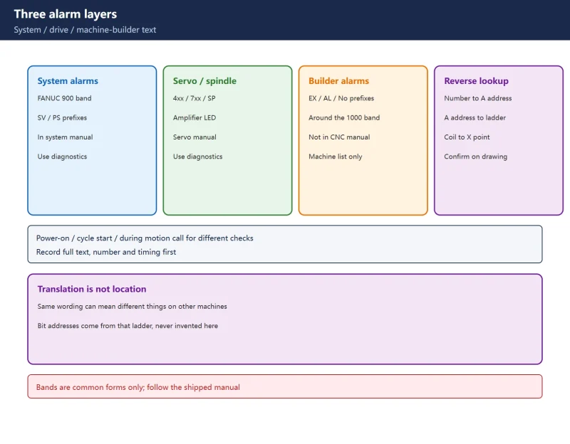
| Old 0-series / 16i / 18i / 21i / 0i-A/B/C | Bare numbers, e.g. 920, 930, 974 | The 900 range itself is the system-alarm band |
| 0i-MD / 0i-D / 0i-MF | Letter prefix, e.g. SV0401, PS0090 | 400 band servo, 000 band program / parameter |
| 30i / 31i / 32i / 0i-F | Two-letter prefixes, same rules | Some numbers differ in meaning from the old generation |
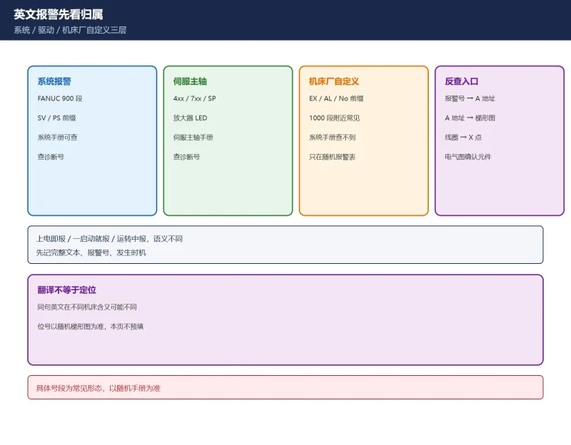
Key point: the same bare 920 is a Watchdog / main-CPU-related alarm in the 0i-C manual, but the 21i-Model A manual B-63085EN/02 writes 920 as SERVO ALARM (1 to 4 AXIS) — swap the axis control card. Same digits, different text, different board. That is why a 0i-D table must not be used on a 0i-C.
2. The 900-Range, Verified Line by Line
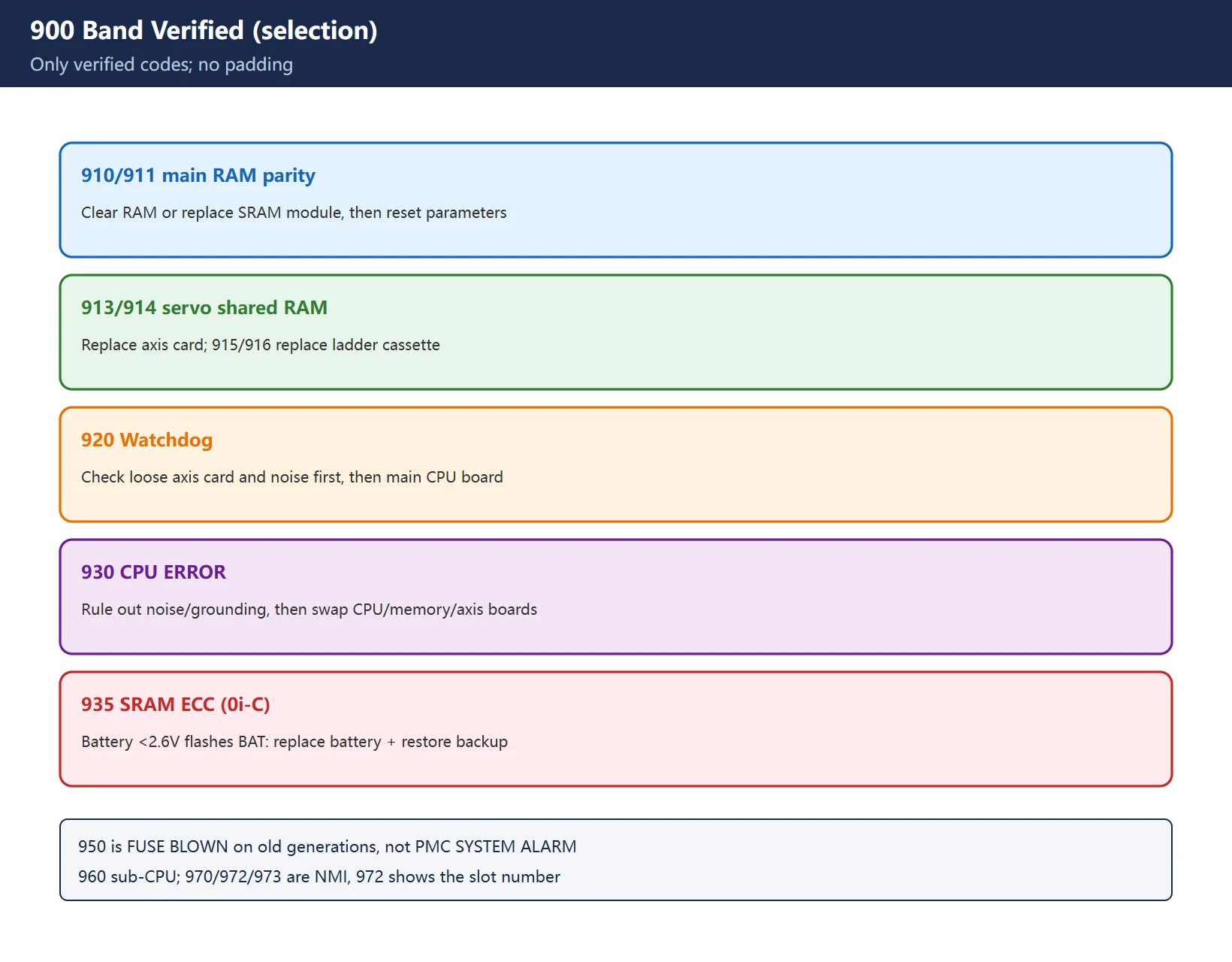
Only verified entries are listed. Numbers that could not be confirmed are left out rather than padded.
| Code | Screen text / meaning | Verified direction |
|---|---|---|
| 910 / 911 | MAIN RAM PARITY | Main RAM / memory board parity — clear RAM or replace SRAM module / motherboard, then reset parameters |
| 912 / 913 | SHARED RAM PARITY (shared with digital servo) | Replace the axis control card |
| 914 | SERVO RAM PARITY (local digital-servo RAM) | Replace the axis control card |
| 915 / 916 | LADDER EDITING CASSETTE RAM PARITY | Replace the ladder editing cassette; low / high byte are separate codes |
| 920 | WATCHDOG ALARM (axes 1–4) | Check axis-card screws and noise first, then main CPU board / axis card; see the same-number note above for the 21i meaning |
| 921 | SUB CPU WATCHDOG | Sub-CPU board or axis 5/6 servo; replace sub-CPU / 5-6 axis card |
| 922 | 7/8 AXIS SERVO SYSTEM ALARM | Replace 7/8 axis servo board; also consider CPU, memory board, power supply |
| 930 | CPU ERROR / CPU INTERRUPT | Rule out noise and cabling before replacing main CPU, memory board, axis card, I/O interface board |
| 935 | SRAM ECC ERROR (0i-C / 0i Mate-C) | Low battery (<2.6 V, BAT blinking) corrupts SRAM — replace battery and restore from backup before suspecting FROM/SRAM module or main board |
| 950 | FUSE BLOWN ALARM | On old 0-series this is a blown fuse (e.g. F14 on +24E), not “PMC SYSTEM ALARM” |
| 960 | SUB CPU ERROR | Replace the sub-CPU board |
| 970 / 972 / 973 | NMI (PMC LSI / other module / unknown) | 970: check PMC side and motherboard; 972: screen shows the faulty option-board slot, swap by slot; 973: cause unknown, swap boards one at a time |
Table 1 Verified 900-range table for 0i-B/0i-C and older generations
Three copied-wrong entries worth calling out:
- 950 is widely mislabeled “PMC SYSTEM ALARM” — that is the 21i-Model A (B-63085EN/02) meaning. On the old 0-series and 0i-B/C public alarm tables, 950 is FUSE BLOWN. Check fuses before replacing a motherboard.
- 935 is not universal — SRAM ECC is specific to the 0i-C / 0i Mate-C generation and tied directly to battery voltage. Back up before clearing SRAM or you wipe parameters, PMC and offsets together.
- “920 = main board or axis card” cannot be settled with one sentence — the manual explicitly covers both main-CPU Watchdog and axis 1–4 servo. Tighten the axis card, clean boards, check shielding and ground, then follow the swap order if it returns.
3. 974 / 975 / 976: Only 975 Uses ADRS
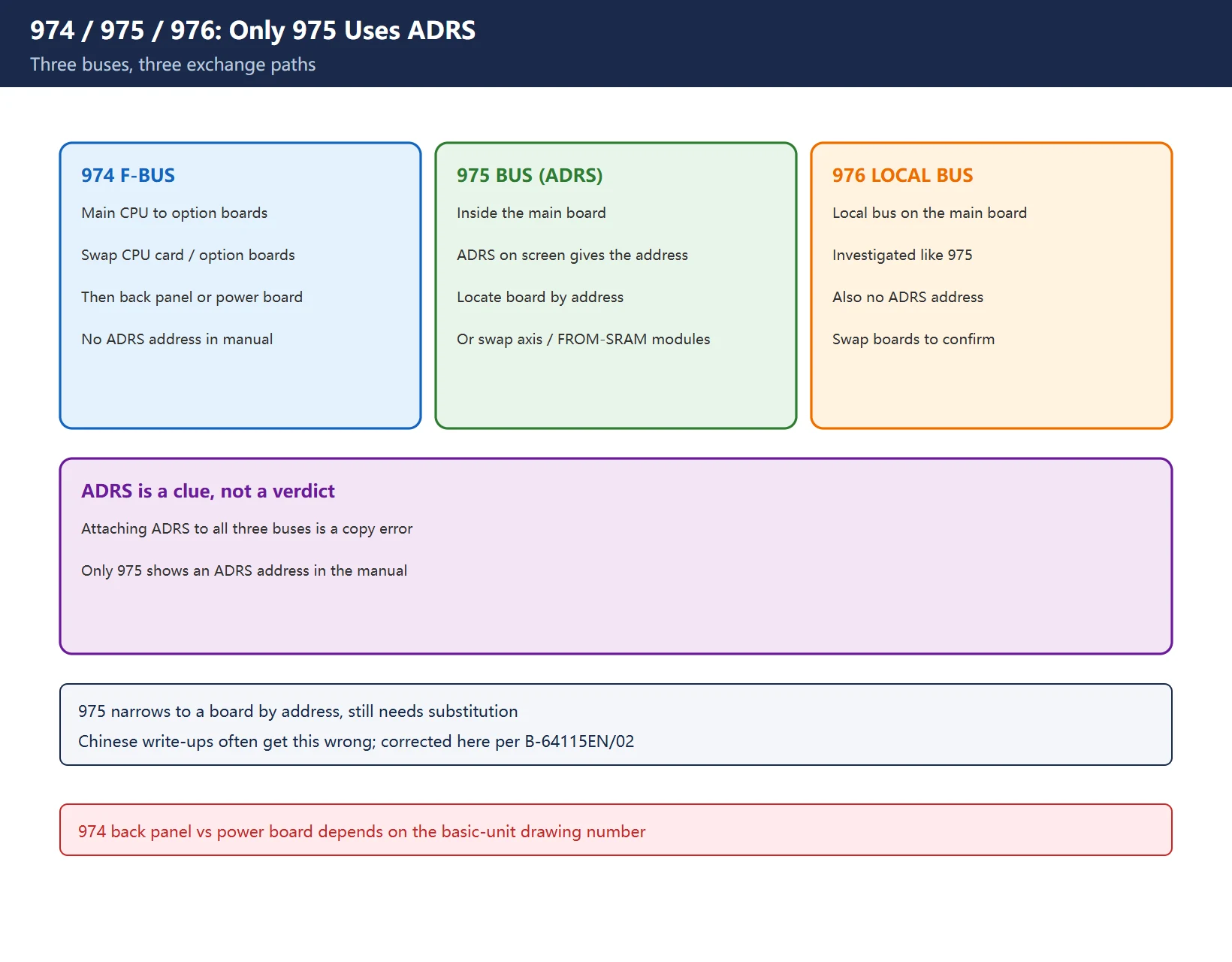
Per 0i-C Maintenance Manual B-64115EN/02 sections 8.35–8.37:
| Alarm | Manual text | Where the data exchange fails | Location method |
|---|---|---|---|
| 974 | F-BUS ERROR | Between main CPU and each option board | Swap CPU card / main board / option boards / back panel one at a time (back panel or power board depends on basic-unit drawing number) |
| 975 | BUS ERROR | Inside the main board between modules | ADRS information on screen gives the address — locate the board by address; or swap CPU card, display control card, axis cards, FROM/SRAM, main board |
| 976 | LOCAL BUS ERROR | Local bus on the main board | Investigated like 975 |
Table 2 How 974 / 975 / 976 differ in path and location method
How to read ADRS: ADRS is the error address shown on screen with 975 (BUS ERROR, data exchange failure inside the main board), narrowing “which part of the motherboard failed” down to a specific board. It is a clue, not a verdict — the manual still says locate by address, then swap to confirm. Chinese write-ups routinely attach ADRS to all three bus errors; that is wrong: 974 (option-board F-BUS) and 976 (local bus) have no ADRS address display in the manual — only 975 does.
4. Swap Order and Board Numbers: Soft Before Hard, Outside Before Inside
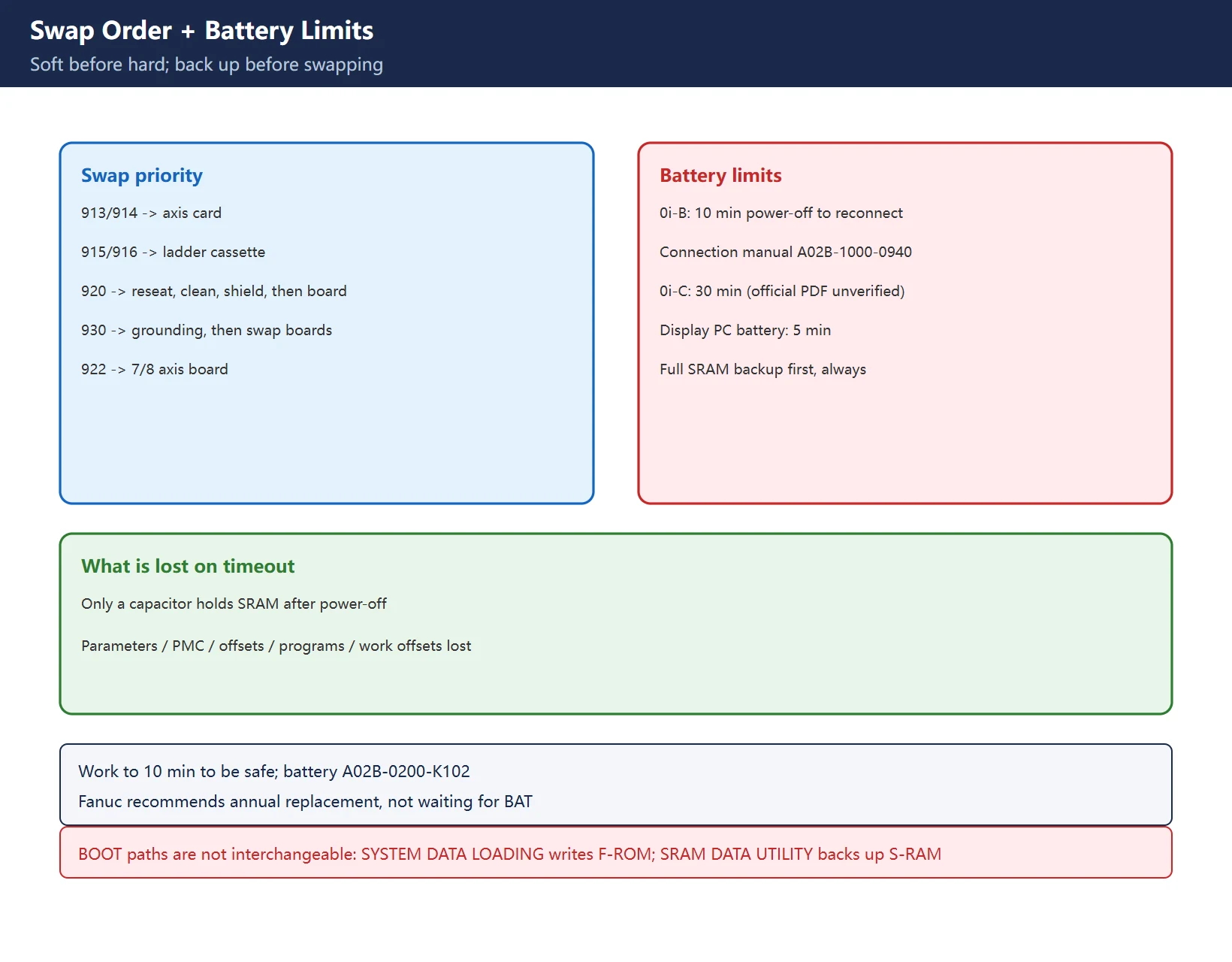
Maintenance data gives a usable order for the 900 range:
| Alarm clue | Suspect first | Action |
|---|---|---|
| 913/914 axis-card RAM parity | Axis control card | Reseat / replace axis card |
| 915/916 ladder cassette RAM | Ladder editing cassette | Replace cassette |
| 920 Watchdog | Loose axis card → noise → main board | Reseat first, clean boards and check shielding, then replace main CPU board |
| 922 axes 7/8 | 7/8 axis servo board | Replace 7/8 axis board; also check CPU / memory / power supply |
| 930 CPU | Noise → main CPU board / memory board | Check grounding, swap one board at a time; don't condemn the CPU outright |
Table 3 Swap priority for 900-range alarms
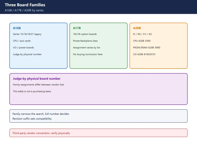
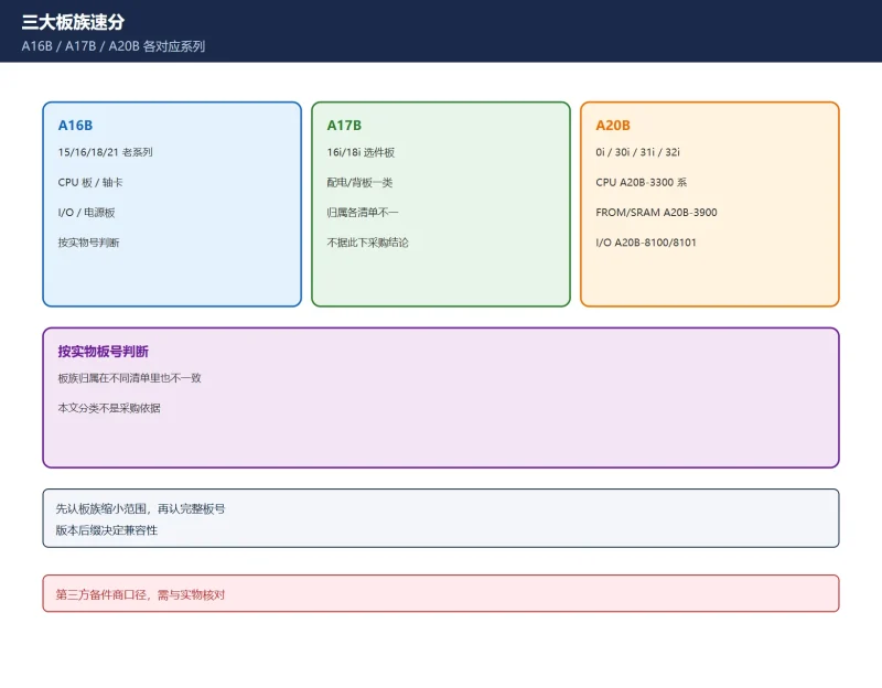
Board numbers (verify against the machine): commonly cited main-board numbers include A16B-2000-017*, A20B-2002-065*, memory boards A16B-2200-010* / A16B-1212-021*, axis card A16B-2200-036* (0i-C 32-bit α series). The trailing asterisk varies by model, servo family and production batch — these are field-circulated lists, not an official “this number always fits this model” confirmation. Before ordering a spare, photograph the full silkscreen of the old board and match it digit by digit with your manual’s board table.
5. BOOT Menu Differences and Battery Time Limits
The BOOT system screen on 0i-B / 0i-C is not identical to 0i-F: 0i-F adds a USER DATA LOADING line for writing user data. The older controls commonly show SYSTEM DATA LOADING (read system files into F-ROM), SRAM DATA UTILITY (SRAM backup / restore), MEMORY CARD FORMAT and so on. The two paths are not interchangeable.
Battery replacement time limits (key correction):
| Control | Power-off to new battery reconnected | Source status |
|---|---|---|
| 0i-B | Within 10 min (step 3 power off → step 5 reconnect) | Quoted from 0i-B connection manual A02B-1000-0940 |
| 0i-C | 30 min | Third-party citation of the 0i-C maintenance manual; official PDF not obtained → unconfirmed |
| CNC display unit with PC functions | Within 5 min | Same 0i-B connection manual |
Table 4 Battery time limits and source status
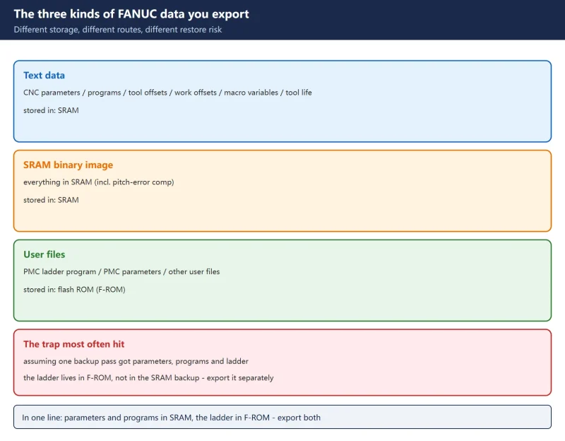
The mechanism is the same in every case: after power-off only a capacitor briefly holds SRAM — exceed the limit and parameters, PMC, offsets, programs and work offsets are lost. The safe practice is to work to the 10-minute figure and always take a full SRAM backup first. Battery part A02B-0200-K102 (Fanuc spec A98L-0031-0012); when BAT blinks, schedule replacement promptly — Fanuc recommends replacing annually rather than waiting for the alarm.
Frequently Asked Questions
Is a 930 alarm on a 0i-C a bad CPU or just noise?
Either can be true. Both the manual and field data put noise / grounding / contact problems before swapping the CPU: power-cycle to see if it is intermittent, check grounding, separation of signal and power wiring, shield termination and board screws; only when it recurs on every power-up and board-by-board substitution isolates the main CPU or memory board do you call it a board failure. Swapping boards without checking noise can kill the replacement too.
What does the ADRS address after a 974 / 975 alarm mean?
ADRS is the error address shown with 975 (BUS ERROR, data exchange failure inside the main board), used to narrow the faulty board before swapping. 974 (F-BUS between option boards) and 976 (local bus) have no ADRS address display in the manual — attaching ADRS to all three bus errors is a copy error.
How long do I have to change the battery on a 0i-B / 0i-C, and what is lost if I exceed it?
The 0i-B connection manual A02B-1000-0940 states 10 min from power-off to reconnecting the new battery (5 min for the display unit’s PC-function battery). 0i-C is commonly quoted as 30 min, but that was not verified against an official PDF here — working to 10 min is safest. Exceeding it loses SRAM parameters, PMC-related parameters, offsets, macro variables, programs and work offsets; a full BOOT SRAM backup beforehand covers all of it.
Last updated: 2026-11-15
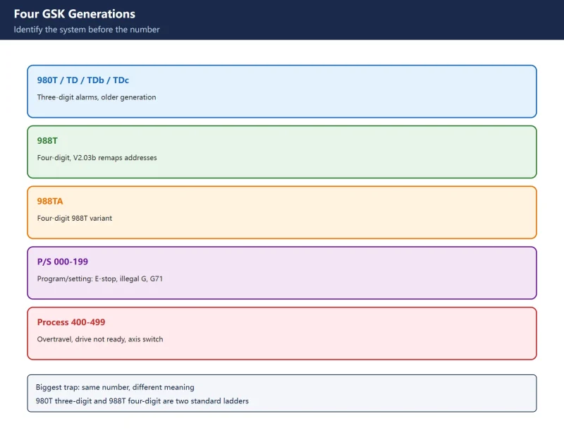
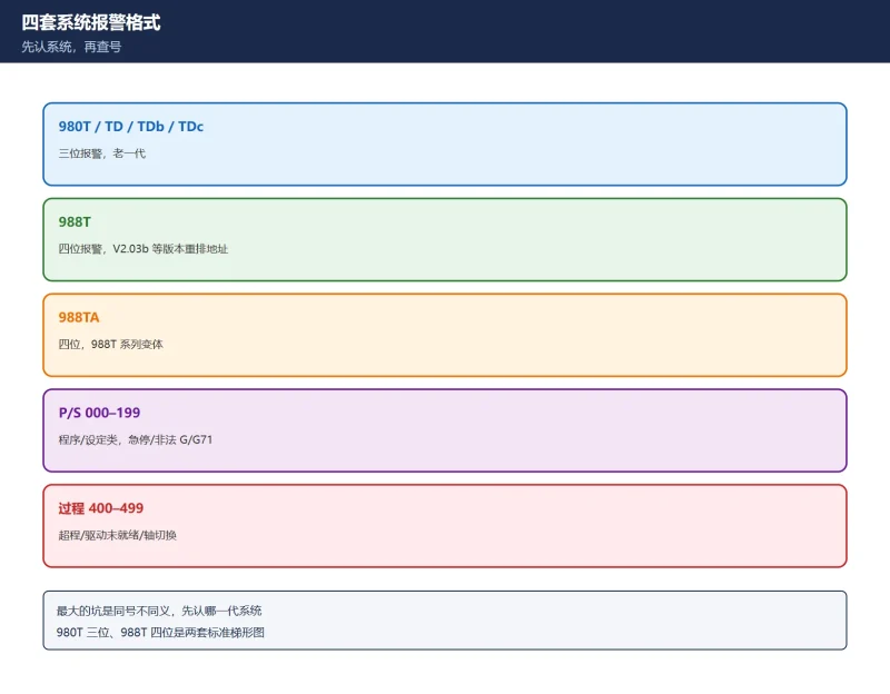
Beyond same-number-different-board: GSK same-number-different-meaning
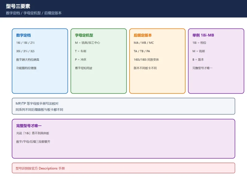
Beyond legacy alarms: 16i/18i/21i identification
Where to go next
- FANUC Troubleshooting — the full guide library: alarms, diagnosis numbers, servo, spindle, PMC and electrical faults, organised by symptom.
- CNC Repair Tools — which instrument measures what: multimeters, clamp meters, insulation testers and oscilloscopes, with the specification that actually matters.
- Remote Technical Support — have the readings reviewed with you: alarm reverse lookup, PMC ladder analysis and servo tuning advice by call. Repair companies and integrators welcome.
- Buying & Ownership Decisions — refurbished vs new, used-machine checks, software licensing and manuals: spend with the field facts in hand.
Read the guide, get the right instrument, or walk the diagnosis through with someone — pick whichever you need.
The original Chinese version — same procedure, with the full field notes.



















暂无评论内容