


You are standing at the cabinet reading the two digits on the spindle amp’s LED. Two mistakes waste the most time: treating “SP9012 on the CNC” and “12 on the amplifier” as two different faults, and swapping a good power module because of a bad code list. This page is sorted by the two digits actually shown on the SPM display, with plain-English meaning, first action, and the decisive check for each.
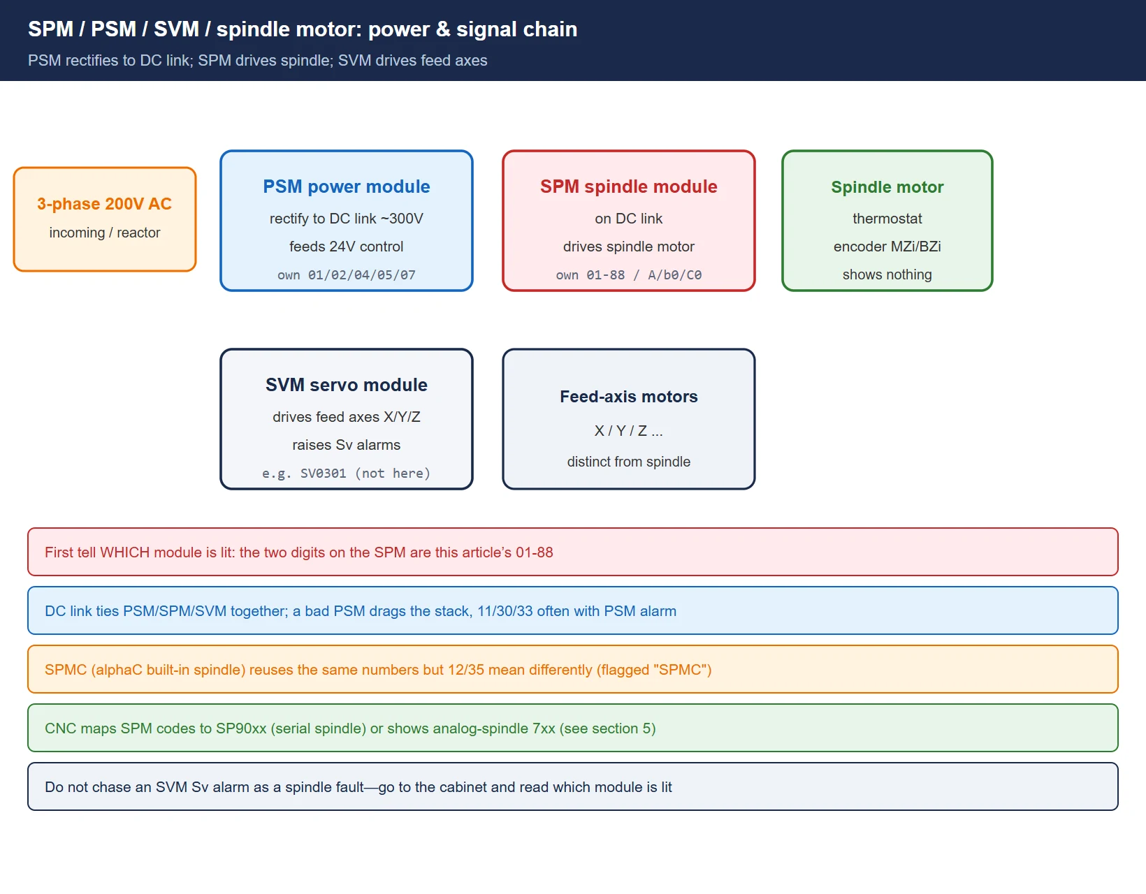
1. Know the cast: SPM / PSM / SVM / spindle motor
In a FANUC serial spindle (α / αi series) the cabinet holds several power modules side by side. Which one is lit, and with what, matters:
- PSM (Power Supply Module): rectifies 3-phase 200 V into the DC link (~300 V) and regulates it, and feeds 24 V control power to the whole stack. Its own LED shows power-side codes like
01/02/04/05/07. - SPM (Spindle Module): hangs on the DC link and drives the spindle motor. Almost all the two-digit codes in this article appear on this SPM STATUS window.
- SVM (Servo Module): also on the DC link, but drives the feed axes (X/Y/Z). It raises
Svalarms (e.g. SV0301), not the SPM codes here—don’t mix them. - Spindle motor itself: carries the thermostat and encoder (MZi/BZi/CZi or magnetic sensor). It shows nothing, yet “motor overheat 01” and “coder disconnect 27” usually originate there.
There is also a confusingly named SPMC (αC-series built-in spindle amp): it reuses the same numeric codes as SPM, but a few (e.g. 12, 35) mean something else. Those are flagged “SPMC” in the table.
2. How to read the display: numeric codes + letter codes (A / A0–A4 / b0 / C0–C2)
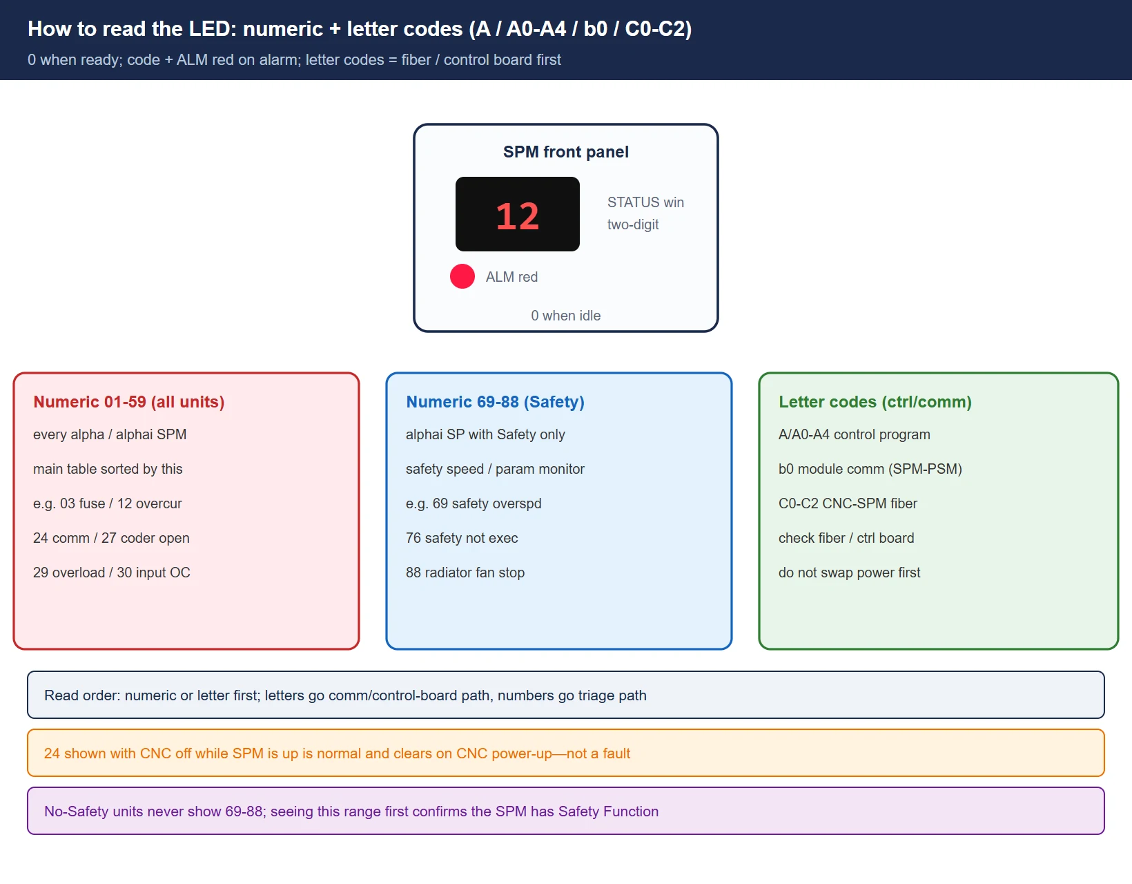
The SPM front has a two-digit 7-segment LED (STATUS window). Standing by it shows 0; on alarm it shows the code and the ALM red LED lights. Three families:
- Pure numeric
01–59: common to all standard α/αi units. This is the main table in section 3. - Numeric
69–88: only on αi SP units equipped with the Safety Function (safety speed monitoring, safety parameters). Machines without the safety option never show this range. - Letter codes: not numbers—control/communication faults—
– A / A0: SPM control program not running; A1/A2: control program processing error; A3: control-board clock error; A4: SRAM parity error.
– b0: communication error between modules (SPM–PSM)—check the cable between the two blocks first, then suspect a module.
– C0/C1/C2: serial communication data error between CNC and spindle module (fiber JA7A/JA7B or the CNC-side board).
Reading tip: the code is raised by the SPM itself and is the same fault shown on the CNC as “SP90xx” (see section 5). A letter code usually means don’t touch the power terminals yet—it is a control board / fiber / 24 V matter.
3. Alarm code full list (sorted by the two digits on the display)
The “Triage” column maps to the three paths in section 4: Replace (module/PSM body—still alarms with cable off, or control-board fault) / Wire (cable, connector, motor, incoming) / Param (init & polarity) / Mech (load, fan, regen). “SPMC” marks αC-series only.
| Code | English | Meaning | First action (triage) | Decisive check / common cause |
|---|---|---|---|---|
| 01 | Motor overheat | Spindle motor overheat | Mech · fan | Motor thermostat tripped; check cooling fan, mechanical bind, sustained overload |
| 02 | Excess speed deviation | Speed deviation too large | Wire · param | Actual speed can't follow command; speed sensor/cable, load, speed-detect param |
| 03 | DC link fuse blown | DC link fuse blown | Replace | Severe overcurrent (often blown IGBT); SPM internal fuse, usually module swap |
| 04 | Input fuse / phase loss | Input fuse / phase loss | Wire (PSM side) | PSM 3-phase 200 V incoming phase loss; check incoming terminals & CX |
| 05 | Control P.S. fuse blown | Control P.S. fuse blown | Wire | AF2/AF3 control-power fuse blown |
| 06 | Overspeed (analog) / temp sensor | Overspeed (analog) or temp sensor | Wire | Analog spindle; motor temp sensor or cable open |
| 07 | Overspeed (digital) | Overspeed (>115% max) | Param · wire | Speed-detect param wrong, power-cable phase reversed, amp fault |
| 08 | +24 V overvoltage | +24 V input overvoltage | Wire | Input voltage high; check 24 V supply |
| 09 | Heat sink overheat | Heat sink overheat | Mech · fan | Amp cooling fan, cabinet airflow blocked |
| 10 | Low input voltage | Low input voltage | Wire | Incoming voltage sag; check wiring & supply |
| 11 | DC link overvoltage | DC link overvoltage | Wire (PSM side) | Regen energy during rapid decel; check PSM / regen resistor |
| 12 | DC link overcurrent | DC link overcurrent | Replace · wire | CRITICAL: motor/power-cable short, IGBT/IPM blown; trips on command = this |
| 13 | CPU memory fault | CPU memory fault | Replace | Control-board fault, swap SPM control PCB |
| 14 | ROM alarm | ROM alarm | Replace | ROM abnormal |
| 15 | Spindle switch seq. | Spindle switch / orient seq. | Param | Magnetic-pole sensor or orient param, MCC timing |
| 16 | RAM fault | RAM fault | Replace | NVRAM/RAM fault, swap control board |
| 17 | NVRAM fault | NVRAM fault | Replace | Swap control board |
| 18 | ROM checksum | ROM checksum | Replace | Program ROM checksum, swap control board |
| 19 | IU offset | U-phase current-detect offset | Replace | Usually SPM control-board fault (on at power-up) |
| 20 | IV offset | V-phase current-detect offset | Replace | Same, V phase |
| 21 | VCMD offset / sensor polarity | Position sensor polarity wrong | Param | After swap, param #4000.0 / #4001.4 polarity reversed |
| 22 | TSA offset | TSA offset | Replace | Control-board fault |
| 23 | ER offset | ER offset | Replace | Control-board fault |
| 24 | Serial data error | Serial data error | Wire | Normal if CNC is off; if it stays, check JA41/JA7A/7A7B fiber & SPM control board |
| 25 | Serial transfer stopped | Serial transfer stopped | Wire | Same, link broken |
| 26 | Cs speed sensor err | Cs contour speed sensor err | Wire | Cs contour speed sensor / cable |
| 27 | Position coder disconnect | Position / encoder signal open | Wire | Check JYA4/JYA3 encoder cable, encoder itself |
| 28 | Cs pos sensor disconnect | Cs contour pos sensor open | Wire | Cs contour position sensor / cable |
| 29 | Continuous overload | Continuous / short-time overload | Mech | Sustained overload (≈30 s / 9 V load meter); check cut & clamp |
| 30 | Input circuit overcurrent | Input-side overcurrent | Wire (PSM side) | PSM / incoming / AC reactor overcurrent; differs from 12—see section 4 |
| 31 | Motor lock / V-sig lost | Motor won't turn / V-sig lost | Wire · mech | Mechanical jam, broken belt, bad speed sensor |
| 32 | Serial LSI RAM fault | Serial LSI RAM fault | Replace | Control-board fault |
| 33 | DC link precharge fail | DC link precharge fail / undervolt | Wire (PSM side) | PSM charge timeout, incoming phase loss, DC-link issue |
| 34 | Parameter out of range | Parameter out of range | Param | Spindle param wrong; not initialized after swap |
| 35 | Gear ratio out of range | Gear ratio out of range | Param | Orient magnetic-sensor param; SPMC meaning differs |
| 36 | Error counter overflow | Error counter overflow | Param | Gear ratio / position-gain param too large |
| 37 | Decel fail after EMG | No decel after EMG | Param | Motor accelerates after EMG; speed-feedback pulse param wrong |
| 39 | Cs 1-rot pos err | Cs 1-rot signal pos err | Wire · param | Cs contour detector param / cable |
| 40 | Cs 1-rot missing | Cs 1-rot signal missing | Wire | Same, signal not generated |
| 41 | Pos coder 1-rot pos err | Pos coder 1-rot pos err | Wire · param | Pos-coder pulse-count param wrong |
| 42 | Pos coder 1-rot missing | Pos coder 1-rot missing | Wire | Same, signal not generated |
| 43 | Diff-spindle coder disconnect | Diff-speed spindle coder open | Wire | Master-spindle coder open in differential-speed mode |
| 44 | A/D converter error | A/D converter error | Replace | Control-board A/D fault |
| 46 | Thread 1-rot fail | Thread 1-rot signal fail | Wire | Encoder sync signal abnormal during threading |
| 47 | Pos coder pulse abnormal | Pos coder pulse count abnormal | Wire · param | MZ/BZ pulse count abnormal, param wrong |
| 49 | Diff speed overspeed | Diff-speed overspeed | Param | Master/slave spindle sync speed diff too large |
| 50 | Sync calc overflow | Sync calc overflow | Param | Sync param wrong |
| 51 | DC link undervoltage | DC link undervoltage | Wire (PSM side) | Low-voltage form of 33 logic |
| 52 | ITP signal stopped 1 | CNC sync ITP stopped 1 | Wire | Inter-module sync fiber |
| 53 | ITP signal stopped 2 | CNC sync ITP stopped 2 | Wire | Same |
| 54 | Long-duration overcurrent | Long-duration overcurrent | Mech · wire | Fast accel or short; check load & cable |
| 55 | Switch signal mismatch | Spindle switch signal mismatch | Param | Hi/lo winding switch contactor / signal mismatch |
| 56 | Ctrl fan stopped | Control fan stopped | Mech | Amp internal fan stopped |
| 57 | PSM regen overtemp | PSM regen resistor overtemp | Wire (PSM side) | PSM regen resistor overtemp |
| 58 | PSM main fan overtemp | PSM main fan overtemp | Wire (PSM side) | PSM main-circuit fan overtemp |
| 59 | PSM internal fan stopped | PSM internal fan stopped | Wire (PSM side) | PSM internal cooling fan stopped (same number, different module than SPM 59) |
| 69 | Safety speed exceeded | Safety speed exceeded | Param | αi SP with Safety only: safety speed monitor tripped |
| 70 | Abnormal axis data | Abnormal axis data | Param | Safety axis-data abnormal |
| 71 | Abnormal safety param | Abnormal safety param | Param | Safety param wrong |
| 72 | Motor speed mismatch | Motor speed mismatch | Wire · param | Motor speed inconsistent under safety monitor |
| 73 | Motor sensor disconnect | Motor sensor disconnect | Wire | Safety encoder / motor sensor open |
| 74 | CPU test alarm | CPU test alarm | Replace | Control-board CPU self-test |
| 75 | CRC test alarm | CRC test alarm | Replace | Control-board CRC self-test |
| 76 | Safety func not executed | Safety func not executed | Param | Safety function not commissioned |
| 77 | Axis number mismatch | Axis number mismatch | Param | Safety config axis number wrong |
| 78 | Safety param mismatch | Safety param mismatch | Param | Safety params disagree on cross-check |
| 79 | Abnormal initial test | Abnormal initial test | Param | Safety initial test abnormal |
| 81 | Motor sensor 1-rot err | Motor sensor 1-rot err | Wire | Safety motor sensor 1-rot signal |
| 82 | Motor sensor 1-rot missing | Motor sensor 1-rot missing | Wire | Same, not detected |
| 83 | Motor sensor signal err | Motor sensor signal err | Wire | Safety motor sensor signal |
| 84 | Spindle sensor disconnect | Spindle sensor disconnect | Wire | Safety spindle sensor open |
| 85 | Spindle sensor 1-rot err | Spindle sensor 1-rot err | Wire | Safety spindle sensor 1-rot signal |
| 86 | Spindle sensor 1-rot missing | Spindle sensor 1-rot missing | Wire | Same, not detected |
| 87 | Spindle sensor signal err | Spindle sensor signal err | Wire | Safety spindle sensor signal |
| 88 | Radiator fan stopped | Radiator fan stopped | Mech | Radiator fan stopped |
| A / A0 | Control prog not running | SPM control program not running | Replace | Control board / program not up |
| A1 / A2 | Control prog error | Control program error | Replace | Control-board fault |
| A3 | Clock error | Clock error | Replace | Control PCB clock |
| A4 | SRAM parity | SRAM parity | Replace | Control-board SRAM |
| b0 | Module comm error | Module comm error (SPM–PSM) | Wire · replace | Check cable between blocks first, then SPM/PSM control board |
| C0/C1/C2 | CNC–SPM serial err | CNC–SPM serial data err | Wire | Fiber JA7A/JA7B or CNC-side serial spindle board |
Note: letter codes
A/b0/C0are not in the same window logic as the numbers but all light the ALM red LED. Seeb0→ check the inter-module cable first; seeC0–C2→ check the CNC–SPM fiber first. Don’t start by swapping a power module.
4. Triage: replace the module / chase the wire / fix the parameter
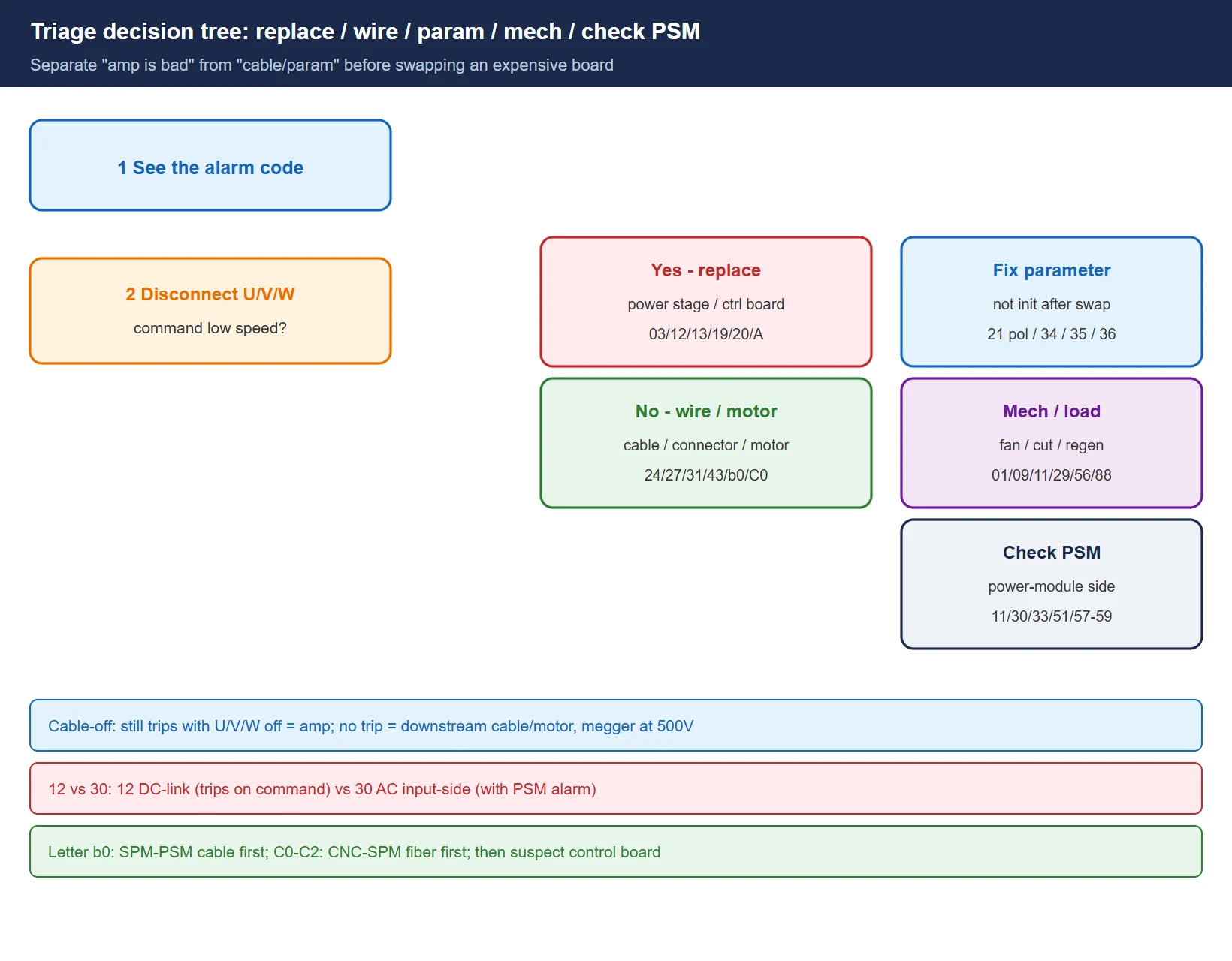
The most valuable field judgment is separating “the amp is bad” from “cable / motor / parameter” so you don’t swap an expensive board by mistake. The table groups the high-frequency codes by first action, with the one-shot decisive check.
| Alarm | First action | Decisive check (how to confirm) |
|---|---|---|
| 03 / 12 (when IGBT blown) / 13 / 16 / 18 / 19 / 20 / 32 / 44 / A0–A4 | Replace | Still alarms immediately with motor U/V/W disconnected at the amp → power stage or control board shorted, it's the amp; A class and 19/20 at power-up are basically control board |
| 04 / 05 / 24 / 25 / 27 / 30 / 31 / 33 / 43 / b0 / C0–C2 | Wire | Fault follows cable/connector/motor: alarm clears when cable removed → downstream (cable or motor); 24 clears after re-seating/replacing fiber → comm link; incoming phase loss 04/33 → PSM incoming |
| 07 / 15 / 21 / 34 / 35 / 36 / 37 / 49 / 50 | Param | Not initialized after swap, polarity #4000.0/#4001.4 reversed, speed/gear-ratio param wrong; fixing param clears it |
| 01 / 02 / 09 / 11 / 29 / 54 / 56 / 88 | Mech / load / fan | Motor overheat → fan & cut; overvoltage 11 → regen; overload 29 → clamp & load meter; fan stop 56/88 → airflow |
| 11 / 30 / 33 / 51 / 57 / 58 / 59 | Check PSM (power module) | These often appear with a PSM-side alarm (e.g. SPM 30 with PSM 1, SPM 33 with PSM 5); fix the power module first |
12 vs 30 (the frequent mix-up): 12 is DC-link overcurrent—trips the instant you command the spindle, usually motor/power-cable short or IGBT/IPM blown. 30 is AC input-side overcurrent—tied to PSM, incoming reactor, 3-phase incoming, often with a PSM-side alarm. Use the “cable-off” method (section 6) to locate before swapping.
5. SP vs SPM on the CNC: SP9012 and SPM 12 are the same fault, not two
The biggest field confusion: “SP9012” on the CNC screen and “12” on the spindle amp LED are the same fault shown in two places—not two alarms.
- On a serial spindle the CNC maps the amp alarm to the
SP90xxfamily:SP9001= amp 01 motor overheat,SP9012= amp 12 DC-link overcurrent,SP9027= amp 27 coder open … the last two digits are exactly the SPM LED code. - So when the CNC shows
SP9012, the SPM LED will also read12, and the object to fix is identical. Don’t clear the SP alarm on one side while “repairing” the amp on the other—double-handling tends to widen the fault. - The genuinely different family is the old analog spindle
7xxalarms (e.g.749/754): those are at the CNC’s analog interface level, with no SPM LED to match, and are handled differently (analog speed command / tachogenerator).
Memory rule: serial spindle SP90xx = amp LED xx; analog spindle 7xx = a different beast.
6. Service notes: protect the person first, then the machine
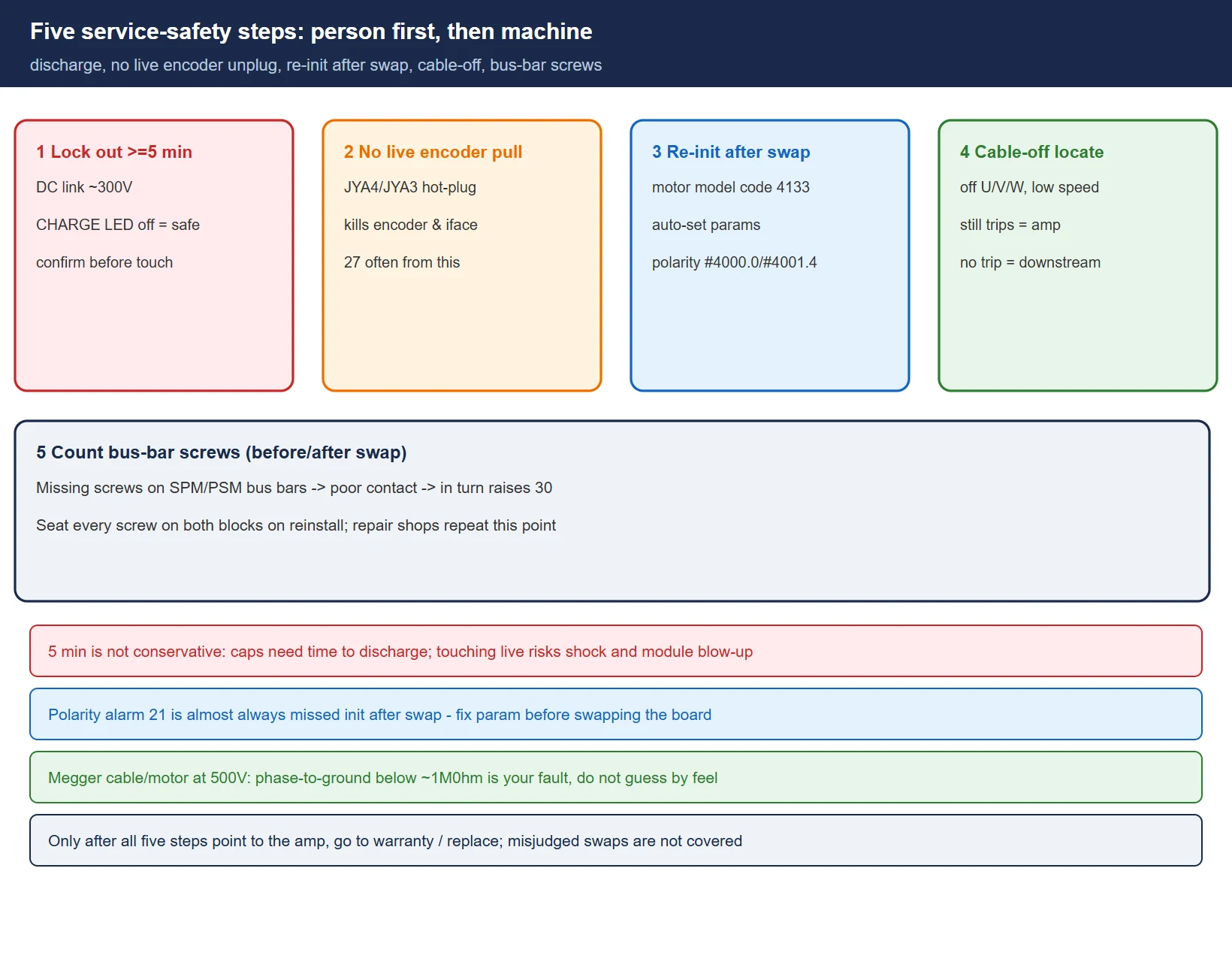
- Lock out and wait ≥ 5 minutes: the SPM/PSM DC link holds ~300 V; the charge LED (CHARGE) must be off before it’s safe. Touching U/V/W or the bus bar before discharge risks shock and module blow-up.
- Never unplug the encoder (JYA4/JYA3) live: coder-open 27 often follows a hot-plug, and live plugging also kills the encoder and SPM interface. Power down and discharge first.
- Always re-initialize spindle parameters after a swap: after replacing the SPM or spindle motor, re-check the motor model code (e.g. 4133), auto-set params, and sensor polarity
#4000.0/#4001.4—polarity alarm21is almost always this step skipped. - Use the “cable-off” method to locate, then decide to swap: disconnect the motor U/V/W at the amp and command low speed—still trips
12immediately → amp power stage shorted; no trip → problem is downstream cable or motor. Megger the cable/motor at 500 V DC; phase-to-ground below ~1 MΩ is your fault. - Count the bus-bar screws before swapping: missing screws on the SPM/PSM bus bars cause poor contact and in turn raise
30. Seat every screw on both blocks when reinstalling (a point repair shops repeat).
Frequently Asked Questions
What is the difference between a FANUC spindle amplifier alarm and a CNC alarm?
The spindle amplifier (SPM) raises 01–88 numeric codes or A/b0/C0 letter codes on its own LED; the CNC maps those to SP90xx (serial spindle) or shows analog-spindle 7xx alarms. They are the same fault viewed from two places—on a serial spindle, SP9012 is simply amp code 12. The difference is only “where you look,” not “whether it’s one fault.”
Does SPM showing 24 mean the amplifier is bad?
Not necessarily, and usually not the amp body. 24 is a serial communication data error between CNC and spindle module: if it shows because the CNC is powered off while the SPM is up, that’s normal and clears when the CNC comes on. If it persists after power-up, re-seat or replace the JA41/JA7A/JA7B fiber and connectors first; only then suspect the SPM control board. Don’t swap the power module up front.
How do I tell FANUC spindle amplifier alarm 12 and 30 apart?
12 = DC-link overcurrent, fault in the SPM power stage, spindle motor, or power cable (trips on command, usually short / IGBT blown). 30 = AC input-side overcurrent, fault in the PSM, incoming reactor, or 3-phase incoming, often with a PSM-side alarm at the same time. In the field use the “cable-off” method: still trips with motor U/V/W off → amp; no trip → downstream cable/motor; if a PSM alarm accompanies it, check the power module first.
Last updated: 2026-10-25
Where to go next
- FANUC Troubleshooting — the full guide library: alarms, diagnosis numbers, servo, spindle, PMC and electrical faults, organised by symptom.
- CNC Repair Tools — which instrument measures what: multimeters, clamp meters, insulation testers and oscilloscopes, with the specification that actually matters.
- Remote Technical Support — have the readings reviewed with you: alarm reverse lookup, PMC ladder analysis and servo tuning advice by call. Repair companies and integrators welcome.
Read the guide, get the right instrument, or walk the diagnosis through with someone — pick whichever you need.
The original Chinese version — same procedure, with the full field notes.








暂无评论内容